evaton technologies Link SDIY User manual

Introduction
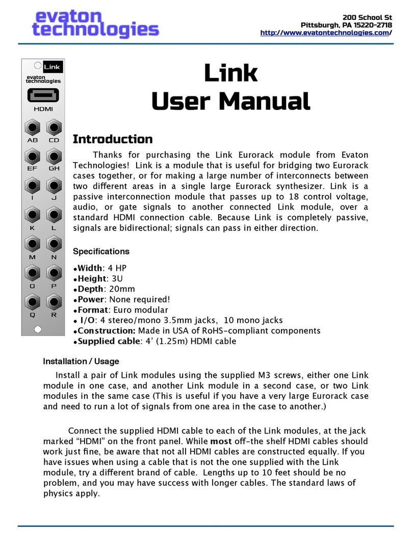
Thanks for purchasing the Link SDIY kit from Evaton Technologies! Link is a
module that is useful for bridging two Eurorack cases together, or for making a
large number of interconnects between two di!erent areas in a single large
Eurorack synthesizer. Link is a passive interconnection module that passes up
to 18 control voltage, audio, or gate signals to another connected Link module,
over a standard HDMI connection cable. Because Link is completely passive,
signals are bidirectional; signals can pass in either direction.
Skill Level
The Link SDIY kit requires basic soldering skills to complete. While all of the
surface-mount components come pre-installed, all remaining components are
standard thru-hole components. These instructions assume you already know
how to solder.
Precautions
Soldering irons are HOT! Be careful not to touch the business end of your
soldering iron at any time. Also note that components that have been soldered
will remain hot for a few moments. If you need to hold something to solder it, it
is recommended NOT to use your fingers. Wear long pants and long sleeves to
avoid solder splash from burning exposed skin.
Tools Required
A few basic electronic assembly tools are needed to complete the assembly
of the circuit board.
Soldering iron. Minimum 25 watt pencil iron; preferred temperature-
controlled, but not necessary.
Link SDIY
Assembly Manual
Revision A
200 School St
Pittsburgh, PA 15220-2718
http://www.evatontechnologies.com/

200 School St
Pittsburgh, PA 15220-2718
http://www.evatontechnologies.com/
Small wire cutter
Electronic solder. 60/40 lead/tin or 63/37 lead/tin, or lead-free. Use
rosin-core solder. Do NOT use acid-core (plumbing) solder! Small-diameter
1
solder is preferred (0.039”)
Pair of needle nose pliers for bending leads and holding components
Small bench vise or “helping hands” (optional) for holding the PCB.
8mm open-end wrench for tightening jack nuts. In a pinch, a 11/32”
wrench or pair of needle nose pliers will work. "
Acidcore music is great. Acid core solder is not.
1
Page 2

200 School St
Pittsburgh, PA 15220-2718
http://www.evatontechnologies.com/
Kit Contents
•2 partially populated printed circuit boards (PCB)
•8x Green Stereo 3.5mm THONKiconn jacks
•20x Black Mono 3.5mm THONKiconn jacks
•2x Stainless Steel, laser-etched faceplates
•1x HDMI cable
•4x faceplate screws
Assembly Instructions
Preparation
To begin assembly, clear a space on your workbench . It helps to have good
2
lighting, and your tools located where they can be easily reached. Plug in your
soldering iron and let it come up to temperature. It helps to have a dampened
sponge nearby, to wipe the solder tip on to keep it clean . Place the bare circuit
3
board in the middle of your work area, with the white silkscreen legend facing
you.
The next few paragraphs will go step-by-step through the process of
assembling the circuit board. You may wish to check these steps o!as you go,
to keep track of your place.
Note that the instructions listed here are for building one Link module.
Repeat the instructions again to build the second module of the pair.
Also note that, while your PCB will have the HDMI connector pre-soldered,
the photos in this assembly document show that connector not installed, to
make it easier to see the components you will be soldering.
Hey, that’s my first step. My bench is always a complete mess!
2
Actually, those nifty brass-wool sponges work even better. Wish I had figured that out 30 years ago...
3
Page 3

200 School St
Pittsburgh, PA 15220-2718
http://www.evatontechnologies.com/
____ Green Thonkiconn Stereo Jacks
J1 thru J4 are stereo
3.5mm jacks. Insert the jack
into the holes on the PCB
carefully; pay attention to
the orientation. The single
external leg on the jack
points towards the HDMI
connector on the board.
For now, only solder the
middle of pin of the jack.
We’ll go back and solder the
other two pins later.
Install all four green jacks
as shown, and solder only
the center pin.
Page 4

200 School St
Pittsburgh, PA 15220-2718
http://www.evatontechnologies.com/
____ Black Thonkiconn Mono Jacks
J5 thru J14 are mono 3.5mm jacks. Just like the green stereo jacks, insert the
jacks carefully, making sure the external leg is facing the HDMI end of the
board. Solder just the middle pin for now. "
Page 5

200 School St
Pittsburgh, PA 15220-2718
http://www.evatontechnologies.com/
____ Align the faceplate
Place the faceplate onto the jacks as shown. Now you can see why we only
soldered one pin of each jack. If there is a jack that isn’t lining up perfectly,
melt the solder on the center pin of that jack and reposition the jack while the
solder is melted, so that it lines up better. Check all the jacks, and make sure
the holes in the faceplate line up with all the jacks. Once you are done, remove
the faceplate temporarily.
____ Solder All Remaining Pins
Now that you are sure all the jacks are aligned properly, solder the
remaining pins on all the jacks. Make sure you don’t miss any; and you may
even want to go back and check your original solder joints when done.
Page 6

200 School St
Pittsburgh, PA 15220-2718
http://www.evatontechnologies.com/
___ Assemble the Faceplate
Put the faceplate back onto
the jacks on the module, and finger-
tighten a nut onto each jack. Once
all the jacks are finger-tightened,
use an 8mm or 11/32” wrench or
socket to make the nuts snug.
NOTE: Be careful not to scratch
the faceplate while tightening the
nuts!
Stainless steel scratches more
easily than anodized aluminum. You
may wish to wrap your wrench or
pliers in adhesive tape before
tightening the nuts, to help avoid
scratching the faceplate. Stainless
steel was used in order to get the
correct stackup thickness needed by
the HDMI connector to allow the
HDMI plug to fully seat, and
anodized aluminum was not
available in that thickness.
Page 7

200 School St
Pittsburgh, PA 15220-2718
http://www.evatontechnologies.com/
___ Assemble the other module
Repeat the above instructions to assemble the second Link module. Follow
the instructions in the user manual on how to install and use your Link
modules!
Congratulations!
With some skill and a little luck, you should now have a fully functioning RF
Nomad that you built yourself. Congratulations!
Please join the Evaton Technologies user forums at:
http://www.evatontechnologies.com/apps/forums
Or, follow us on Facebook at https://www.facebook.com/evatontechnologies
And please join the mailing list: http://www.evatontechnologies.com/join
the RF Nomad FAQ at http://www.evatontechnologies.com/rf-nomad
Warranty
Regretfully, because this is a DIY project, Evaton Technologies cannot
warrant the finished project, but please do contact
DIY kit, and Russ will try to help you out.
Page 8
Table of contents
Other evaton technologies Control Unit manuals
Popular Control Unit manuals by other brands
TP-Link
TP-Link TL-SM321A installation guide
LOVATO ELECTRIC
LOVATO ELECTRIC DCTL Series instruction manual
Fracarro
Fracarro MOD-WL16 operating instructions

joucomatic
joucomatic ASCO 343 Series Installation
Inficon
Inficon VGC501 operating manual

DROPSA
DROPSA nano Progressive USER OPERATION AND MAINTENANCE MANUAL

Mitsubishi Electric
Mitsubishi Electric PAC-AH125 installation manual

Elektrogas
Elektrogas EVRM-NA manual
Landis+Gyr
Landis+Gyr S4e UtiliNet user manual

IBM
IBM BladeCenter 4-Port installation guide

Festo
Festo ZSB-1/8 operating instructions
Bristan
Bristan N2 SHCDIV G Installation instructions and user guide
