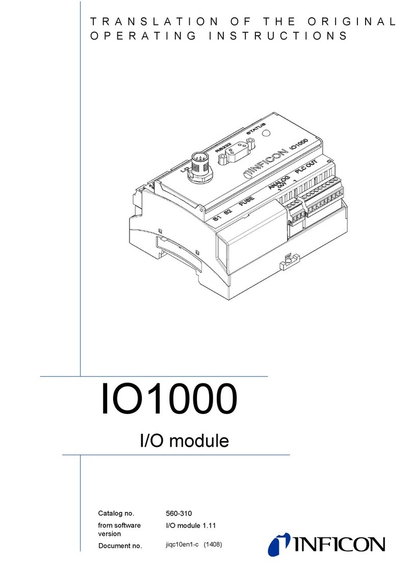
Inficon VGC501 User manual

Operating
M
Incl. EU Declar
a
tina96e1-b (20
Singl
Cont
r
VGC50
M
anual
ation of Confor
m
16-12)
e-Ch
a
r
ol U
n
1, VGC
5
m
ity
a
nne
l
n
its
5
02, V
G
l
, Tw
o
G
C503
o
-Ch
a
a
nnel & Th
h
ree-
C
C
han
n
1
n
el

2
Prod
u
V
alid
u
ct Identi
f
ity
f
ication
I
n
n
T
T
T
I
f
e
I
f
c
o
V
U
W
A
n
all communi
c
a
meplate:
his document
398
-
398
-
398
-
he part numb
e
his manual is
your unit doe
q
uipped with
t
not indicated
o
rrespond to
t
V
GC501 (Sing
l
U
nit) by analo
g
W
e reserve th
e
A
ll dimensions
c
ations with I
N
Spe
c
t
applies to pr
o
-
481
-
482
-
483
er (Mod.-No.)
based on fir
m
e
s not work as
t
he above fir
m
otherwise in
t
t
he unit VGC
5
l
e-Channel C
o
g
y.
e
right to mak
e
are indicated
N
FICON, plea
imen namepl
a
o
ducts with p
a
(VGC501, Single
-
(VGC502, Two-
C
(VGC503, Three
-
can be found
m
ware version
described in
t
m
ware version
t
he legends, t
h
5
03 (Three-C
h
o
ntrol Unit) a
n
e
technical ch
a
in mm.
s
e specify th
e
a
te
a
rt numbers:
-
Channel Control
hannel Control U
n
-
Channel Control
U
on the produ
c
V1.04.
t
his documen
t
(→58).
h
e illustration
s
h
annel Control
d to the VGC
5
a
nges withou
t
tina96e1-b (2016-12)
e
information
o
Unit)
nit)
Unit)
c
t nameplate.
t
, please che
c
s
in this docu
m
l
Unit). They
a
5
02 (Two-Ch
a
t
prior notice.
VGC501_VGC502_VGC503.
o
o
n the produc
t
c
k that it is
m
ent
a
pply to the
a
nnel Control
o
m
t

tina96e1-b (2016-12) VGC501_VGC502_VGC503.om 3
The Control Units VGC501, VGC502 and VGC503 are used together with
INFICON gauges for total pressure measurement. All products must be operated in
accordance with their respective operating manuals.
The scope of delivery consists of the following parts:
1× Control Unit
1× Power cord (country-specific)
1× Rubber bar
2× Rubber feet
4× Collar screws
4× Plastic sleeves
1× CD-ROM (manuals, tools, …)
1× EU Declaration of Conformity
1× Installation Manual
Intended Use
Scope of Delivery

4tina96e1-b (2016-12) VGC501_VGC502_VGC503.om
Contents
Product Identification 2
Validity 2
Intended Use 3
Scope of Delivery 3
Contents 4
1Safety 6
1.1 Symbols Used 6
1.2 Personnel Qualifications 6
1.3 General Safety Instructions 7
1.4 Liability and Warranty 7
2Technical Data 8
3Installation 12
3.1 Installation, Setup 12
3.1.1 Rack Installation VGC501 12
3.1.2 Rack Installation VGC502, VGC503 15
3.1.3 Installation in a control panel 16
3.1.4 Use as Desk-Top Unit 17
3.2 Mains Power Connector 18
3.3 Gauge Connectors CH 1, CH 2, CH 3 19
3.4 CONTROL Connector VGC501 21
3.5 CONTROL Connector VGC502, VGC503 22
3.6 RELAY Connector VGC502, VGC503 22
3.7 Interface Connector USB Type B 24
3.8 Interface Connector USB Type A 24
3.9 Interface Connector Ethernet 25
4Operation 26
4.1 Front panel 26
4.2 Turning the VGC50x On and Off 28
4.3 Operating Modes 28
4.4 Measurement Mode 31
4.5 Parameter Mode 33
4.5.1 Switching Function Parameters 34
4.5.2 Gauge parameters 38
4.5.3 Gauge Control 46
4.5.4 General Parameters 50
4.5.5 Test Parameters 58
4.5.6 Data Logger Mode 61
4.5.7 Parameter Transfer Mode 63
5Communication Protocol (Serial Interface) 65
5.1 Data Transmission 66
5.2 Communication Protocol 67
5.3 Mnemonics 68
5.4 Measurement Mode 70
5.5 Switching Function Parameters 76
5.6 Gauge Parameters 77
5.7 Gauge Control 84
5.8 General Parameters 85
5.9 Data Logger Parameters 91
5.10 Parameter Transfer 92
5.11 Test Parameters 92
5.12 Further 97
5.13 Example 98
6Maintenance 99
7Troubleshooting 100
8Repair 101
9Accessories 101
10 Storage 101
11 Disposal 101

tina96e1-b (2016-12) VGC501_VGC502_VGC503.om 5
Appendix 102
A: ConversionTables 102
B: Firmware Update 103
C: Ethernet Configuration 106
C 1: Connect the VGC50x to a Network 106
C 2: Connect the VGC50x to a Computer 107
C 3: Ethernet Configuration Tool 107
D: Literature 110
ETL Certification 112
EU Declaration of Conformity 113
For cross-references within this document, the symbol (→XY) is used; for cross-
references to further documents listed under ‘Literature’, use is made of the symbol
(→[Z]).

6
1
S
1.1
S
S
F
1.2
P
S
afety
S
ymbols
U
S
ymbols for
r
F
urther sym
b
P
ersonne
l
U
sed
r
esidual risk
s
b
ols
l
Qualific
a
I
I
I
m
<
A
h
i
s
a
tions
D
A
I
nformation o
n
W
I
nformation o
n
C
a
I
nformation o
n
m
inor equipm
e
The
The
The
Pre
s
Do
n
……> Lab
e
Skill
e
A
ll work desc
r
h
ave suitable
i
nstructed by
t
A
NGER
n
preventing
a
W
ARNING
n
preventing
e
a
ution
n
correct han
d
ent damage.
lamp / displa
y
lamp / displa
y
lamp / displa
y
s
s the key (ex
a
n
ot press any
e
ling
e
d person
n
r
ibed in this d
o
technical trai
n
t
he end-user
o
a
ny kind of ph
y
e
xtensive equi
d
ling or use.
D
y
is lit.
y
flashes.
y
is off.
a
mple: para
m
key.
n
el
o
cument may
n
ing and the
n
o
f the product
y
sical injury.
pment and e
n
D
isregard can
l
eter key).
only be carri
e
ecessary exp
.
tina96e1-b (2016-12)
n
vironmental
d
lead to malfu
n
e
d out by pers
o
p
erience or w
h
VGC501_VGC502_VGC503.
o
d
amage.
n
ctions or
o
ns who
o have been
o
m

tina96e1-b (2016-12) VG
C
1.3 Gen
e
Instr
u
Disco
n
1.4 Liabi
C
501_VGC502_VGC503.om
e
ral Safet
y
u
ctions
n
necting dev
lity and
W
y
ice
W
arranty
Adhere
work yo
The dis
c
user.
To disc
o
Commu
INFICO
user or
t
•disre
•use t
•mak
e
•use t
men
t
Disconn
acc. to
E
to the applic
a
o
u are going t
o
DANGE
R
Contact
w
introduce
d
Make sur
e
trate into
t
c
onnecting d
e
o
nnect the un
i
u
nicate the sa
f
N assumes n
o
third parties
e
gard the infor
t
he product in
e
any kind of i
t
he product wi
t
ation.
n
ecting device
E
N 61010-1
a
ble regulatio
n
o
do and cons
DANGER
R
: mains volta
g
w
ith live parts
i
d
or any liqui
d
e
no objects
e
t
he equipmen
e
vice must be
i
t from the m
a
f
ety instructio
n
o
liability and
t
mation in this
a non-confor
m
nterventions
(
th accessorie
s
s and take th
e
i
der the safet
y
g
e
s extremely h
d
s penetrate i
n
e
nter through
t
t
.
readily identif
i
ins supply, y
o
n
s to all other
t
he warranty i
s
document
m
ing manner
modifications
,
s
not listed in
e
necessary
p
y
instructions
i
h
azardous wh
e
n
to the unit.
t
he louvers a
n
f
iable by and
e
o
u must unplu
g
users.
s rendered n
u
, alterations e
t
the correspo
n
p
recautions fo
r
i
n this docum
e
e
n any object
s
n
d no liquids
p
e
asily reache
d
g
the mains c
a
u
ll and void if
t
t
c.) on the pr
o
n
ding product
7
r
all
e
nt.
s
are
p
ene-
d
by the
a
ble.
t
he end-
o
duct
docu-

8tina96e1-b (2016-12) VGC501_VGC502_VGC503.om
2 Technical Data
Voltage 100 … 240 V (ac) ±10%
Frequency 50 … 60 Hz
Power consumption
VGC501
VGC502
VGC503
≤45 W
≤65 W
≤90 W
Overvoltage category II
Protection class 1
Connection European appliance connector IEC 320 C14
Temperature
Storage
Operation
–20 … +60 °C
+ 5 … +50 °C
Relative humidity ≤80% up to +31 °C,
decreasing to 50% at +40 °C
Use indoors only
max. altitude 2000 m NN
Pollution degree II
Degree of protection IP30
Number
VGC501
VGC502
VGC503
1
2
3
Gauge connections per channel RJ45 (FCC68), 8-pin (→20)
D-Sub, 15-pin, female (→20)
(connected in parallel)
Compatible gauges
Pirani PSG400, PSG400-S, PSG100-S, PSG101-S,
PSG500, PSG500-S, PSG502-S, PSG510-S,
PSG512-S, PSG550, PSG552, PSG554
Pirani / Capacitance PCG400, PCG400-S, PCG550, PCG552,
PCG554
Cold cathode PEG100, MAG500, MAG504
Cold cathode / Pirani MPG400, MPG401, MPG500, MPG504
Hot ionization / Pirani BPG400, BPG402, HPG400
Capacitance CDG020D, CDG025, CDG025D,
CDG025D-X3, CDG045, CDG045-H,
CDG045D, CDG045D2, CDG045Dhs,
CDG100, CDG100D, CDG100D2,
CDG100Dhs, CDG160D, CDG200D
Hot ionization / Capacitance /
Pirani
BCG450
Voltage +24 V (dc) ±5%
Ripple <±1%
Current 0 … 1 A (per channel)
Power 25 W (per channel)
Fuse protection 1.5 A (per channel) with PTC element, self-
resetting after turning the unit off or disconnect-
ing the gauge. The supply conforms to the
grounded protective extra low voltage require-
ments.
Mains specifications
Ambience
Gauge connections
Gauge supply

tina96e1-b (2016-12) VGC501_VGC502_VGC503.om 9
Front panel
VGC501
VGC502, VGC503
via 3 keys
via 4 keys
Remote control via USB type B interface
via Ethernet interface
Measurement ranges depending on gauges (→[1] … [27])
Measurement error analog
Gain error
≤0.01% F.S. (typical)
≤0.10% F.S. (over temperature range, time)
Offset error ≤0.01% F.S. (typical)
≤0.10% F.S. (over temperature range, time)
Measurement rate analog ≥100 / s
Display rate ≥10 / s
Filter time constant
Slow
Normal
Fast
8 s (fg= 0.02 Hz)
800 ms (fg= 0.2 Hz)
160 ms (f
g
= 1 Hz)
Measurement units mBar, hPa, Torr, Pa, Micron, V
Offset correction for linear gauges
Calibration factor 0.10 … 10.00
A/D converter resolution 0.001% F.S.
(the measurement values of BPG, HPG, BCG
and CDGxxxD are transmitted digitally)
Number
VGC501
VGC502
VGC503
2
4 (user-assignable)
6 (user-assignable)
Reaction delay ≤10 ms, if switching threshold close to meas-
urement value (for larger differences consider
filter time constant)
Adjustment range depending on gauge (→36, 37)
Hysteresis ≥1% F.S. for linear gauges,
≥10% of measurement value for logarithmic
gauges
Contact type floating changeover contact
Load max. 60 V(dc), 30 W (ohmic)
30 V(ac), 1 A (ohmic)
Service life
Mechanical
Electrical
1×10⁸cycles
1×10⁵cycles (at max. load)
Contact positions →23
Connector
VGC501 (CONTROL)
D-Sub appliance connector, male, 15-pin
(pin assignment →21)
VGC502, VGC503 (RELAY) D-Sub appliance connector, female, 25-pin
(pin assignment →22)
Number 1
Reaction time ≤10 ms
Operation
Measurement values
Switching functions
Switching function relays
Error signal

10 tina96e1-b (2016-12) VGC501_VGC502_VGC503.om
Contact type floating normally open contact
Load max. 60 V(dc), 0.5 A, 30 W (ohmic)
30 V(ac), 1 A (ohmic)
Service life
Mechanical
Electrical
1×10⁸cycles
1×10⁵cycles (at max. load)
Contact positions →23
Connector
VGC501 (CONTROL)
D-Sub appliance connector, male, 15-pin
(pin assignment →21)
VGC502, VGC503 (RELAY) D-Sub appliance connector, female, 25-pin
(pin assignment →22)
Number
VGC501
VGC502
VGC503
1
2 (1 per channel)
3 (1 per channel)
Voltage range –5 … +14.5 V (dc)
If no gauge is connected, +14.5 V (dc) is output
Deviation from display value ±20 mV
Output resistance <50 Ω
Measuring signal vs. pressure depending on gauge (→[1] … [27])
CONTROL connector
VGC501
D-Sub appliance connector, male, 15-pin
(pin assignment →21)
VGC502, VGC503 D-Sub appliance connector, male, 9-pin
(pin assignment →22)
Number 1
Voltage range 0 … +10 V (dc)
Resolution 1 mV
Accuracy ±20 mV
Internal resistance <50 Ω
Measuring signal vs. pressure programmable
CONTROL connector D-Sub appliance connector, male, 9-pin
(pin assignment →22)
Protocol FAT file system
file handling in ASCII format
Protocol ACK/NAK, ASCII with 3-character mnemonics
Data format bi-directional data flow, 1 start bit, 8 data bits,
1 stop bit, no parity bit, no handshake
Transmission rate 9600, 19200, 38400, 57600, 115200
Protocol ACK/NAK, ASCII with 3-character mnemonics,
Data format bi-directional, 1 start bit, 8 data bits, 1 stop bit,
no parity bit, no handshake
Transmission rate 9600, 19200, 38400, 57600, 115200
IP Address DHCP (default) or manual setting (→106)
MAC Address readable via "MAC" parameter
Error signal relay
Analog outputs
Recorder output
(VGC502, VGC503 only)
USB Type A interface
USB Type B interface
Ethernet interface

tina96e1-b (2016-12) VG
C
Dimens
Use
Weight
C
501_VGC502_VGC503.om
ions [mm]
V
GC50
1
V
GC50
2
For inc
o
VGC50
1
VGC50
2
VGC50
3
1
2
, VGC503
o
rporation int
o
1
2
3
o
a rack or co
n
n
trol panel or
a
0.85 kg
1.10 kg
1.14 kg
a
s a desk-top unit
11

12
3 I
n
3.1 I
3.1.1
n
stallati
o
nstallatio
Rack Inst
a
Guide rail
o
n
n, Setup
a
llation
VG
T
d
T
D
w
I
n
b
G
C501
Th
e
trai
the
he unit is suit
e
e
sk-top unit.
Pu
t
tre
m
op
e
he unit is des
i
D
IN 41 494. F
o
w
ith it.
DA
If t
h
cla
s
ac
c
Ta
k
the
n
order to red
u
ly equip the r
a
Skilled
p
e
unit may onl
ning and the
n
end-user of t
h
e
d for incorp
o
DAN
G
t
ting a produc
t
m
ely hazardo
u
e
ration and m
a
igned for inst
a
o
r this purpos
e
DAN
G
NGER: prote
c
h
e product is i
s
s of the rack
c
ording to the
k
e appropriat
e
protection cl
a
u
ce the mech
a
a
ck chassis a
d
G
p
ersonnel
y be installed
n
ecessary ex
p
h
e product.
o
ration into a 1
G
ER
t
which is visi
b
u
s. If the prod
u
a
ke sure it is
n
a
llation into a
e
, four collar
s
G
ER
c
tion class of
t
nstalled in a r
a
(protection a
g
EN 60204-1 r
e
measures fo
a
ss.
a
nical strain o
d
apter with a
g
G
uide rail
by persons
w
p
erience or w
h
9" rack or a c
o
b
ly damaged i
u
ct is visibly d
n
ot inadverte
n
1
9" rack chas
s
crews and pl
a
t
he rack
a
ck, it is likel
y
g
ainst foreign
e
gulations for
r
the rack to
m
n
the front pa
n
g
uide rail.
tina96e1-b (2016-12)
w
ho have suit
a
h
o have been
c
ontrol panel
o
nto operation
d
amaged do n
n
tly put into o
p
sis adapter a
c
a
stic sleeves
a
y
to lower the
p
bodies and w
a
r
switching ca
b
m
eet the spec
i
n
el of the VG
C
VGC501_VGC502_VGC503.
o
a
ble technical
instructed by
o
r for use as a
can be ex-
ot put it into
p
eration.
c
cording to
a
re supplied
p
rotection
a
ter) e.g.
b
inets.
i
fications of
C
50x, prefera
-
o
m
-

tina96e1-b (2016-12) VG
C
Mou
n
Heig
C
501_VGC502_VGC503.om
n
ting height
ht 2 rack ch
a
Height
a
ssis adapte
2 rack chassi
S
r
Heig
h
i
s adapter (→
S
ecure the ra
c
Th
e
be
e
Ra
c
Hei
h
t 2
, 13)
c
k chassis ad
a
e
maximum a
d
e
xceeded an
d
c
k chassis ada
g
ht 2
Rack instal
l
Height 3
a
pter in the ra
c
d
missible am
b
d
the air circul
a
p
te
r
ation
rack chassis
a
ck frame.
b
ient tempera
t
a
tion must no
t
Height 3
a
dapter (→
,
ure (→8)
m
t
be obstructe
13
,
14)
m
ust not
d.

14
Height 3 ra
c
c
k chassis a
F
t
w
dapter
Slide th
e
… and fa
supplied
w
or incorporati
o
w
o collar scre
w
Secure
Mount t
h
VGC50
1
e
VGC501 int
a
sten the VG
C
with it.
o
n into a 19"
r
w
s and plasti
c
the rack ada
p
The maxi
m
be exceed
he adapter p
a
1 using the s
c
Rack ch
a
Height 3
o the adapter
C
501 to the ra
c
r
ack chassis
a
c
sleeves) is a
p
ter in the rac
k
m
um admissib
ed and the ai
r
a
nel as upper
e
c
rews supplie
d
a
ssis adapte
r
A
dapter
p
(Height 2
…
c
k chassis ad
a
a
dapter, heigh
t
v
ailable (Acc
e
k
frame.
l
e ambient te
m
r
circulation m
e
xtension to t
h
d
with the ada
p
p
anel
to height 3)
tina96e1-b (2016-12)
a
pter using th
e
t 3, an adapt
e
e
ssories →
m
perature (→
ust not be ob
s
he front pane
l
pter panel.
VGC501_VGC502_VGC503.
o
e
screws
e
r panel (incl.
101).
8) must no
t
s
tructed.
of the
o
m
t

tina96e1-b (2016-12) VG
C
3.1.2 Rac
k
V
G
C
Guid
C
501_VGC502_VGC503.om
k
Installati
o
C
502, VGC
5
e rail
o
n
5
03
S
…
s
u
The uni
t
DIN 41
4
with it.
In orde
r
prefera
b
S
lide the VG
C
…
and fasten t
h
u
pplied with th
t
is designed
f
494. For this
p
DANGE
R
If the pro
d
class of t
h
accordin
g
Take app
the prote
c
r
to reduce th
e
b
ly equip the
r
C
501 into the r
h
e adapter pa
n
e VGC501.
f
or installation
p
urpose, four
DANGER
R
: protection cl
d
uct is installe
h
e rack (prote
c
g
to the EN 60
2
r
opriate mea
s
c
tion class.
e
mechanical
s
r
ack chassis
a
Guide
r
H
a
ck chassis a
d
n
el to the rac
k
into a 19" ra
c
collar screws
ass of the rac
d
in a rack, it
c
tion against
f
2
04-1 regulati
ures for the r
a
s
train on the f
r
a
dapter with a
a
il
H
eight 3
dapter …
k
chassis ada
p
c
k chassis ad
a
and plastic sl
c
k
is likely to lo
w
f
oreign bodie
s
i
ons for switc
h
a
ck to meet t
h
ront panel of
t
guide rail.
p
ter using the
a
pter accordi
n
e
eves are su
p
w
er the protec
t
s
and water) e
h
ing cabinets.
h
e specificatio
n
t
he VGC502/
5
15
screws
n
g to
p
plied
t
ion
.g.
n
s of
5
03,

16
3.1.3
Height 3 ra
c
Installati
o
panel
VGC501
c
k chassis a
o
n in a con
t
F
dapter
t
rol
Secure
Slide th
e
… and fa
supplied
w
DA
If t
h
cla
s
ac
c
Ta
k
the
or mounting t
h
the rack ada
p
The maxi
m
be exceed
e
VGC502/50
a
sten the ada
p
with the VGC
5
DAN
G
NGER: prote
c
h
e product is i
s
s of the rack
c
ording to the
k
e appropriat
e
protection cl
a
h
e VGC501 i
n
Rack ch
a
Height 3
p
ter in the rac
k
m
um admissib
ed and the ai
r
3 into the rac
k
p
ter panel to t
h
5
02/503.
G
ER
c
tion class of
t
nstalled in a r
a
(protection a
g
EN 60204-1 r
e
measures fo
a
ss.
n
to a control p
The
m
ture (
circul
a
ssis adapte
r
k
frame.
l
e ambient te
m
r
circulation m
k
chassis ada
p
h
e rack chass
i
t
he rack
a
ck, it is likel
y
g
ainst foreign
e
gulations for
r
the rack to
m
anel, the follo
w
m
aximum ad
m
→
8) must
n
a
tion must no
t
tina96e1-b (2016-12)
m
perature (→
ust not be ob
s
pter …
i
s adapter usi
n
y
to lower the
p
bodies and w
a
r
switching ca
b
m
eet the spec
i
wing cut-out i
s
m
issible ambi
e
n
ot be excee
d
o
t be obstruct
e
VGC501_VGC502_VGC503.
o
8) must no
t
s
tructed.
n
g the screw
s
p
rotection
a
ter) e.g.
b
inets.
i
fications of
s
required:
e
nt tempera-
d
ed and the ai
e
d.
o
m
t
s
r

tina96e1-b (2016-12) VG
C
VG
C
3.1.4 Use
C
501_VGC502_VGC503.om
C
502, VGC5
0
as Desk-
T
0
3
T
op Unit
For red
u
support
S
…
For mo
u
quired:
For red
u
bly sup
p
S
…
The VG
adhesi
v
u
cing the me
c
the unit.
S
lide the VG
C
…
and secure i
t
u
nting the VG
C
u
cing the me
c
p
ort the unit.
S
lide the VG
C
…
and secure i
t
G
C50x may al
s
v
e rubber feet
c
hanical strain
C
501 into the
c
t
with four M3
C
502/503 int
o
c
hanical strain
C
502/503 into
t
t
with four M3
s
o be used as
and a slip-on
on the front
p
c
ut-out of the
c
or equivalent
o
a control pa
n
The maxim
u
ture (→8
)
circulation
m
on the front
p
t
he cut-out of
or equivalent
a desk-top u
n
rubber bar ar
e
p
anel of the V
G
c
ontrol panel
…
screws.
n
el, the follow
i
u
m admissibl
e
) must not be
m
ust not be o
b
p
anel of the V
G
the control p
a
screws.
n
it. For this p
u
e
supplied wit
G
C501, prefe
r
…
ng cut-out is
r
e
ambient tem
exceeded an
d
b
structed.
G
C502/503,
p
a
nel …
rpose, two se
h it.
17
r
ably
r
e-
pera-
d
the air
p
refera-
lf-

18
3.2
M
M
ains Po
w
w
er Conn
e
T
w
I
f
a
e
ctor
Stick th
e
… and
s
DA
Inc
o
ev
e
Us
e
po
w
gro
wit
h
he unit is sup
p
w
ith your syste
the unit is in
s
nd turned on
v
The s
o
fuse-p
r
1
e
two supplie
d
s
lip the suppli
e
DAN
G
NGER: line v
o
o
rrectly groun
e
nt of a fault.
e
only a 3-co
n
w
er connecto
r
und. The prot
h
out protectiv
e
plied with a p
o
e
m, use your
o
s
talled in a sw
v
ia a central
d
o
cket must be
rotected with
1
0 A
max
d
rubber feet
t
e
d rubber bar
G
ER
o
ltage
ded products
n
ductor power
r
may only be
ection must n
o
e
ground.
o
wer cord. If t
h
o
wn, suitable
c
i
tching cabin
e
d
istributor.
o
the rear par
t
Select a lo
c
maximum
a
exceeded (
e
(→8).
onto the bott
o
can be extre
m
cable with pr
o
p
lugged into
a
o
t be nullified
h
e mains con
n
c
able with pro
t
t, the mains v
tina96e1-b (2016-12)
r
t of the botto
m
c
ation where t
a
mbient temp
e
e.g. due to s
u
o
m edge of th
m
ely hazardo
u
o
tective grou
n
a
socket with
a
by an extens
i
n
ector is not
c
t
ective groun
d
v
oltage should
VGC501_VGC502_VGC503.
o
m
plate …
he admissibl
e
e
rature is not
n irradiation)
e
front panel.
u
s in the
n
d. The mains
a
protective
i
on cable
c
ompatible
d
(3×1.5 mm
3
)
be supplied
o
m
e
)
.

tina96e1-b (2016-12) VG
C
Groun
d
3.3 Gau
g
CH 2
,
C
501_VGC502_VGC503.om
d Connectio
g
e Conne
c
,
CH 3
n
c
tors CH
1
On the
r
connec
t
stand.
For eac
parallel:
•one
•one
1
,
Protecti
v
groundi
n
r
ear of the un
i
t
ed via a grou
n
h channel the
:
RJ45 applian
D-Sub applia
Connect t
h
cable set
a
(electrom
a
(→8).
Caution:
M
Only one
(connecti
o
damaged
DANGE
R
Accordin
g
hazardou
s
Only con
n
1
ve
ng
i
t is a screw e
n
d conductor,
re are two co
n
ce connector,
n
ce connecto
r
h
e gauge to th
a
vailable from
a
gnetic comp
a
Caution
M
ultiple conn
e
sensor may
b
o
n CH Aor C
H
.
DANGER
R
: Hazardous
v
g
to EN 6101
0
s
.
n
ect a protecti
1
only at once
n
abling the V
G
e.g. with the
p
n
nections ava
female, 8-pin
r
, female, 15-
p
e CH 1, CH 2
us (→sales li
tibility) senso
r
e
ction
e connected
t
H
B). Otherwi
s
v
oltage
, voltages ex
c
v
e low voltag
e
Do
n
t
h
(int
e
p
r
G
C50x where
protective gr
o
a
ilable which
a
n
(CH A)
p
in (CH B)
2
or CH 3 con
n
i
terature) or y
o
r
cable. Use
c
t
o each of the
s
e the conne
c
c
eeding 30 V
(
e
(PELV).
n
ot unfasten
h
is screw
e
rnal ground
rotection)
necessary to
o
und of the pu
m
a
re connected
n
ector via a s
e
o
ur own, scre
e
ompatible ga
u
channels
c
ted sensors
m
(
ac) or 60 V (
d
19
be
m
p
in
e
nsor
e
ned
u
ges
m
ay be
d
c) are

20
P
C
P
in assignm
e
C
H 3
A
pplianc
e
A
pplianc
e
e
nt CH 1, C
H
e
socket RJ4
e
socket D-S
P
a
P
a
H
2,
5
ub
P
in assignmen
ppliance con
n
Pin Sig
n
1
2
3
4
5
6
7
8
Sup
p
Sup
p
Sig
n
Ide
n
Sig
n
Stat
u
HV
_
HV
_
P
in assignmen
ppliance con
n
Pin Sig
n
1
2
3
4
5
6
7
8
9
10
11
12
13
14
15
EMI
Sig
n
Stat
u
HV
_
Sup
p
n.c.
Deg
Sup
p
n.c.
Ide
n
Sup
p
Sig
n
Rx
D
TxD
Cha
t of the femal
e
n
ectors:
n
al
ply
ply common
n
al input
n
tification
n
al common
us
_
L
_
H / HV_EMI
t of the femal
e
n
ectors:
n
al
status
n
al input
us
_
H / HV_EMI
ply common
as
ply
n
tification
ply
n
al common
D
ssis
e
8-pin RJ45
+24 V (dc)
GND
(measuring s
i
e
15-pin D-Su
(measuring s
i
GND
+24 V (dc)
+24 V (dc)
gnal 0 … +1
0
b
gnal 0 … +1
0
tina96e1-b (2016-12)
0
V (dc))
0
V (dc))
VGC501_VGC502_VGC503.
o
o
m
This manual suits for next models
2
Table of contents
Other Inficon Control Unit manuals