manuals.online logo
Brands
  1. Home
  2. •
  3. Brands
  4. •
  5. Swagelok
  6. •
  7. Control Unit
  8. •
  9. Swagelok IPT Series Operating instructions

Swagelok IPT Series Operating instructions

CRD 0227 Kit Contents
IPT Series Ball-Seal and Soft-Seal Poppet
Check Valve
Service Instructions
➀A gasket is only used in assemblies with an FK end fitting.
Kit Contents
This kit contains the parts shown below.
Cone RingBall-Seal
Poppet
Soft-Seal
Poppet
or
Cover Spring Gasket➀
or
Tools Required
Part Size/Type Tool
Valve body —
Gland nut
See Table 1
Capable of 320 ft·lb (434 N·m)
See Table 1
Poppet —
Poppet
Cover/cone ring and
gland nut threads
Christo-Lube®MCG 111
Moly-Lit™anti-seize
Bench vise
Open-end wrench
(removal only)
Torque wrench
Crow’s foot adapter
Dowel rod
Lubricants/fluids
End Connection End Connection Size (in.) Gland Nut Hex Size (in.)
Female Cone
and Thread
Medium-Pressure
1/4 7/8
3/8 7/8
9/16 1 3/8
3/4 1 3/8
11 3/4
Female Cone
and Thread
High-Pressure
1/4 7/8
3/8 1 1/8
9/16 1 3/8
Female NPT
1/8 5/8
1/4 3/4
3/8 1
1/2 1 3/8
3/4 1 1/2
11 3/4
FK Series
Medium-Pressure
1/4 3/4
3/8 1 3/8
1/2 1 3/8
9/16 1 3/8
3/4 1 7/8
Table 1
Exploded View
*Bold indicates kit component.
Soft-Seal Poppet Check Valve Components
Gland nut Check valve body
Gasket
(FK ends only)
Cone ring
Cover
Poppet
assembly
Spring
Assembly
with NPT end
connections
only
Gland nut Check valve body
Gasket
(FK ends only)
Cone ring
Cover
Poppet
assembly
Spring
Ball-Seal Poppet Check Valve Components
Assembly
with cone and
thread or FK
series end
connections
Assembly
with NPT end
connections
only
Assembly
with cone and
thread or FK
series end
connections
2
Reassembly
1. Insert the spring into the larger hole of the body.
Disassembly
1. Remove the valve from the system, by removing
both of the end connections, with a backup wrench
on the gland nut.
2. Place the valve body in a vise.
3
•WARNING
Before removing the valve from service,
to avoid personal injury, you must:
• Depressurize the system
• Cycle the valve
• Purge the system to remove any residual
system media left in the valve
NOTICE
Do not scratch any sealing surfaces while
following these instructions. Scratches
on sealing surfaces may affect valve
performance.
3. Remove the gland nut using an open-end wrench.
4. Remove and discard the following components:
gasket (if applicable), cover/cone ring, poppet, and
spring.
5. Clean the valve body and gland nut. Ensure that the
threads are not damaged or galled.
#2 Disassembly
2. Lube the O-ring and the poppet assembly lightly
with Christo-Lube®MCG 111 lubricant applied to
the entire largest outer diameter (OD) surface of
the poppet. Assemble into the body on top of the
spring. For a ball seal, make sure the round ball part
is facing upward. For a soft seal, make sure that the
end with the O-ring faces away from the spring.
3. Ensure the poppet moves freely inside the body by
pushing down on the poppet with the dowel rod.
4. For assemblies with cone and thread or FK series
end connections, lube the external angles of the
cover by applying Moly-Lit™anti-seize lubricant
lightly.
For assemblies with NPT end connections, lube the
external angles of the cone ring by applying Moly-Lit
anti-seize lubricant lightly.
Gland nut
Wrench
Gasket
Cover/
Cone ring
Poppet
Spring
Spring
Dowel rod
Poppet
Light Moly-Lit anti-seize
lubricant
Light Moly-Lit
anti-seize lubricant
Light Christo-lube
MCG 111
lubricant
(Shown: ball-seal poppet
for cone and thread or
FK series end connection) Poppet
Spring
For additional information, see swagelok.com.
Swagelok — TM Swagelok Company
Christo-Lube — TM ECLI Products, LLC
Moly-Lit — TM Anti-Seize Technology
©2022 Swagelok Company
January 20222, Rev-
MS-CRD-0227
7. Lube the gland nut threads by applying Moly-Lit
anti-seize lubricant liberally. Assemble it nger-tight
into the body.
End
Connection
End
Connection
Size
(in.)
Gland Nut Torque Values
316➁and Alloy 2507
Required Torque
ft·lb (N·m)
Female Cone
and Thread
Medium-
Pressure
1/4 55 to 60 (74.5 to 81.3)
3/8 55 to 60 (74.5 to 81.3)
9/16 220 to 240 (298 to 325)➀
3/4 220 to 240 (298 to 325)
1 280 to 320 (380 to 434)
Female Cone
and Thread
High-Pressure
1/4 55 to 60 (74.5 to 81.3)
3/8 65 to 70 (88.1 to 94.9)
9/16 220 to 240 (298 to 325)
Female NPT
1/8 35 to 40 (47.5 to 54.2)
1/4 40 to 45 (54.2 to 61.0)
3/8 55 to 60 (74.5 to 81.3)
1/2 220 to 240 (298 to 325)
3/4 220 to 240 (298 to 325)
1 280 to 320 (380 to 434)
FK Series
1/4 40 to 45 (54.2 to 61.0)
3/8 190 to 210 (258 to 285)
1/2 190 to 210 (258 to 285)
9/16 190 to 210 (258 to 285)
3/4 280 to 320 (380 to 434)
Table 2
➀ For information on NACE material, contact your authorized Swagelok
sales and service center.
➁ Torque values do not apply to 316 stainless steel NACE material.
5. For assemblies with FK series end connection only:
Assemble the gasket onto OD of the cover.
6. Assemble the cover or cone ring into the body.
Ensure that the edge of the hole in the cover or
cone ring sits against the poppet ball (for ball-seal
design) or against the O-ring (for soft-seal design). 8. Torque the gland nut according to Table 2.
9. Using the dowel rod, tap the back of the poppet
assembly through the outlet in the body to properly
set the poppet.
10. Wipe off any excess lubricant.
Gasket
Cover
Cover Poppet
Liberal Moly-Lit anti-seize
lubricant
Gland nut
Gland nut
Dowel rod
Outlet

Other manuals for IPT Series

3

Other Swagelok Control Unit manuals

Swagelok DF Series Operating instructions

Swagelok

Swagelok DF Series Operating instructions

Swagelok AFS Series Operating instructions

Swagelok

Swagelok AFS Series Operating instructions

Swagelok S60P Steam Series Technical specifications

Swagelok

Swagelok S60P Steam Series Technical specifications

Swagelok SK Series Operating instructions

Swagelok

Swagelok SK Series Operating instructions

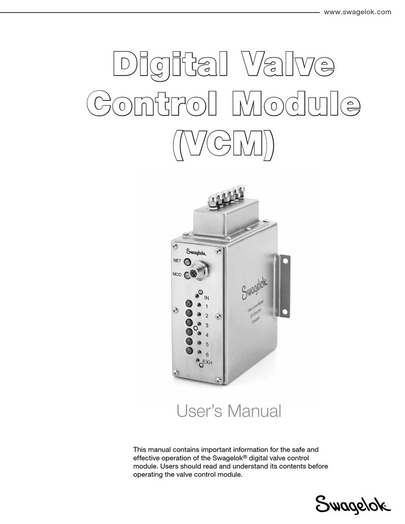
Swagelok VCM User manual

Swagelok

Swagelok VCM User manual

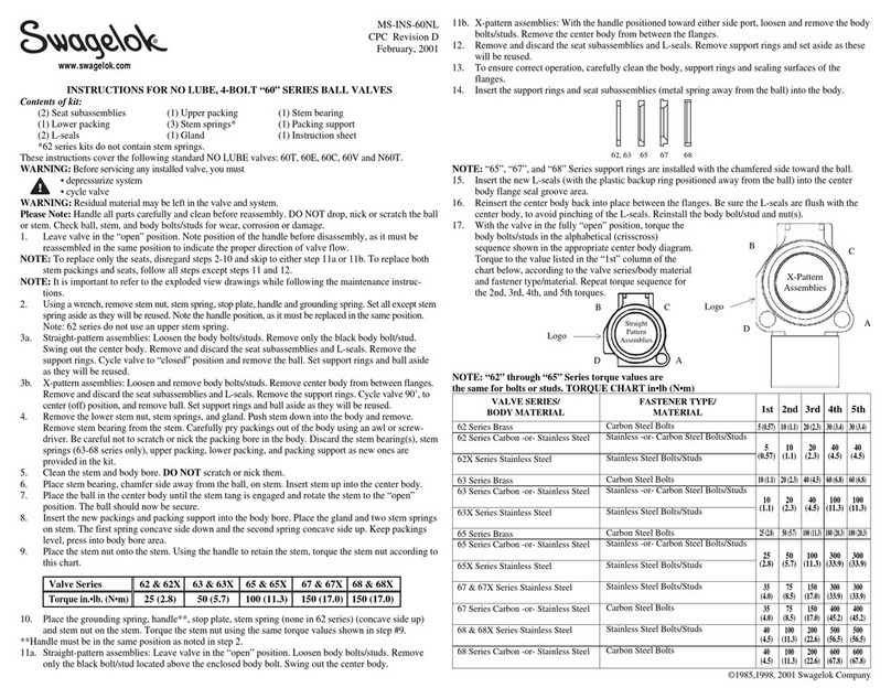
Swagelok 60 Series User manual

Swagelok

Swagelok 60 Series User manual

Swagelok RHPS Series User manual

Swagelok

Swagelok RHPS Series User manual

Swagelok S60 Series User manual

Swagelok

Swagelok S60 Series User manual

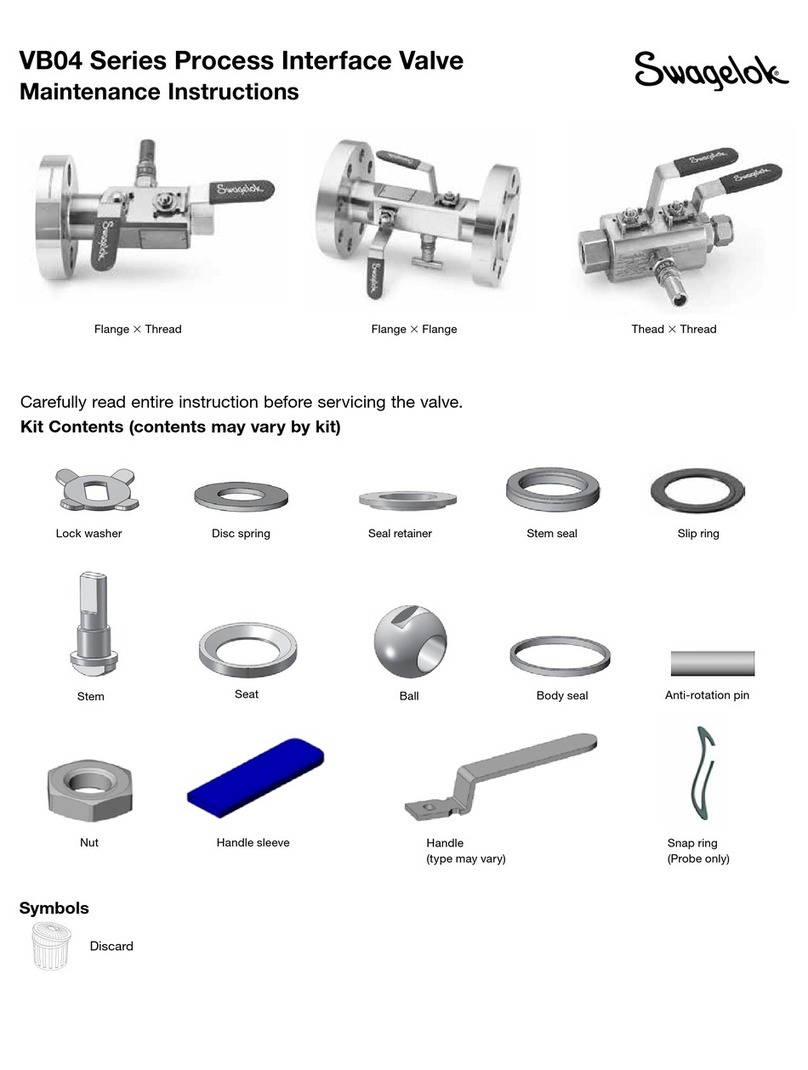
Swagelok VB04 Series Technical specifications

Swagelok

Swagelok VB04 Series Technical specifications

Swagelok IPT Series User manual

Swagelok

Swagelok IPT Series User manual

Swagelok 83DXL Series Operating and maintenance instructions

Swagelok

Swagelok 83DXL Series Operating and maintenance instructions

Swagelok IPT Series User manual

Swagelok

Swagelok IPT Series User manual

Swagelok 60 Series User manual

Swagelok

Swagelok 60 Series User manual

Swagelok XS Series Operating instructions

Swagelok

Swagelok XS Series Operating instructions

Swagelok VB03 Series User manual

Swagelok

Swagelok VB03 Series User manual

Swagelok RHPS Series User manual

Swagelok

Swagelok RHPS Series User manual

Popular Control Unit manuals by other brands

HACH LANGE sc200 user manual

HACH LANGE

HACH LANGE sc200 user manual

Behringer 2500 Series quick start guide

Behringer

Behringer 2500 Series quick start guide

Siemens SIMOTION SCOUT Configuration manual

Siemens

Siemens SIMOTION SCOUT Configuration manual

iSMA iSMA-B-AAC20 user manual

iSMA

iSMA iSMA-B-AAC20 user manual

Wilo RexaBloc RE Installation and operating instructions

Wilo

Wilo RexaBloc RE Installation and operating instructions

Honeywell VP513A manual

Honeywell

Honeywell VP513A manual

PVA PC200 Series owner's manual

PVA

PVA PC200 Series owner's manual

Niko 16-656-01 manual

Niko

Niko 16-656-01 manual

BFT CSB Xtreme Installation and user manual

BFT

BFT CSB Xtreme Installation and user manual

THORLABS EVOA800F user guide

THORLABS

THORLABS EVOA800F user guide

Telit Wireless Solutions BlueMod+S42M Command reference guide

Telit Wireless Solutions

Telit Wireless Solutions BlueMod+S42M Command reference guide

Hochiki S772 Information guide

Hochiki

Hochiki S772 Information guide

Singmai Electronics SM08 user manual

Singmai Electronics

Singmai Electronics SM08 user manual

Bosch FLM-420-EOL4W-D installation guide

Bosch

Bosch FLM-420-EOL4W-D installation guide

CTI 2550 Installation and operation guide

CTI

CTI 2550 Installation and operation guide

Draper LVC-IV Wiring instructions

Draper

Draper LVC-IV Wiring instructions

Texas Instruments TRF7960TB user guide

Texas Instruments

Texas Instruments TRF7960TB user guide

WDT EmETXe-i92U0 user manual

WDT

WDT EmETXe-i92U0 user manual

manuals.online logo
manuals.online logoBrands
  • About & Mission
  • Contact us
  • Privacy Policy
  • Terms and Conditions

Copyright 2025 Manuals.Online. All Rights Reserved.