JUSTSTANDOUT JSO16048208 User manual

Hybrid Inverter
JUSTSTANDOUT SMART HYBRID 16KW INVERTER MANUAL
JSO16048208anual

Contents
1. Safety Introductions ⋯⋯⋯⋯⋯⋯⋯⋯⋯⋯⋯⋯⋯⋯⋯⋯⋯⋯⋯ 01
2. Product instructions⋯⋯⋯⋯⋯⋯⋯⋯⋯⋯⋯⋯⋯⋯⋯⋯⋯⋯⋯ 01-04
2.1Product Overview
2.2Product Size
2.3Product Features
2.4Basic System Architecture
3. Installation ⋯⋯⋯⋯⋯⋯⋯⋯⋯⋯⋯⋯⋯⋯⋯⋯⋯⋯⋯⋯⋯⋯⋯ 05-21
3.1Parts list
3.2Mounting instructions
3.3Battery connection
3.4Grid connection and backup load connection
3.5PV Connection
3.6CT Connection
3.6.1 Meter Connection
3.7Earth Connection(mandatory)
3.8WIFI Connection
3.9Wiring System for Inverter
3.10 Typical application diagram of diesel generator
3.11 Single phase (230Vac) parallel Connection diagram
3.12 Split phase (120/240Vac) parallel Connection diagram
3.13 Parallel Connection for 230/400 three phase
3.14 Pcs Parallel Connection for 120/208 three phase
3.15 Parallel Connection for 120/208 three phase
4. OPERATION ⋯⋯⋯⋯⋯⋯⋯⋯⋯⋯⋯⋯⋯⋯⋯⋯⋯⋯⋯⋯⋯⋯⋯ 22
4.1Power TION/OFF
4.2Operation and Display Panel
5. LCD Display Actions ⋯⋯⋯⋯⋯⋯⋯⋯⋯⋯⋯⋯⋯⋯⋯⋯⋯⋯⋯⋯ 23-35
5.1Main Screen
5.2Solar Power Curve
5.3Curve Page-Solar & Load & Grid
5.4System Setup Menu 5.5 Basic Setup Menu
5.6Battery Setup Menu
5.7System Work Mode Setup Menu
5.8Grid Setup Menu
5.9Generator Port Use Setup Menu
6. Mode ⋯⋯⋯⋯⋯⋯⋯⋯⋯⋯⋯⋯⋯⋯⋯⋯⋯⋯⋯⋯⋯⋯⋯⋯⋯⋯ 35-37
7. Fault Information and processing ⋯⋯⋯⋯⋯⋯⋯⋯⋯⋯⋯⋯⋯ 37-40

8. Limitation of Liability ⋯⋯⋯⋯⋯⋯⋯⋯⋯⋯⋯⋯⋯⋯⋯⋯⋯⋯ 40
9. Datasheet ⋯⋯⋯⋯⋯⋯⋯⋯⋯⋯⋯⋯⋯⋯⋯⋯⋯⋯⋯⋯⋯⋯⋯⋯ 41-42
10. Appendix I ⋯⋯⋯⋯⋯⋯⋯⋯⋯⋯⋯⋯⋯⋯⋯⋯⋯⋯⋯⋯⋯⋯⋯ 43-44
11. Appendix II⋯⋯⋯⋯⋯⋯⋯⋯⋯⋯⋯⋯⋯⋯⋯⋯⋯⋯⋯⋯⋯⋯⋯ 45


About This Manual
The manual mainly describes the product Information, guidelines for installation, operation and
maintenance. The manual cannot include complete Information about the photovoltaic (PV)
system.
How to Use This Manual
Read the manual and other related documents before performing any operation on the inverter.
Documents must be stored carefully and be available at all times.
Contents may be periodically updated or revised due to product development. The Information
in this manual is subject to change without notice. The latest manual can be acquired via
1. Safety Introductions
· This chapter contains important safety and operating instructions. Read and keep this manual
for future reference.
· Before using the inverter, please read the instructions and warning signs of the battery and
corresponding sections in the instruction manual.
· Do not disassemble the inverter. If you need maintenance or repair, take it to a professitional
service center.
· Improper reassembly may result in electric shock or fire.
· To reduce risk of electric shock, disctionnect all wires before aempng any maintenance or
cleaning. Turning off the unit will not reduce this risk.
· Caution: Tionly qualified perstionnel can install this device with battery.
· Never charge a frozen battery. · For optimum operation of this inverter, please follow required
specification to select appropriate cable size. It is very important to correctly operate this
inverter.
· Be very cautious when working with metal tools on or around batteries. Dropping a tool may
cause a spark or short circuit in batteries or other electrical parts, even cause an explosition.
· Please strictly follow installation procedure when you want to disconnect AC or DC terminals.
Please refer to "Installation" section of this manual for the details.
· Grounding instructions - this inverter should be connected to a permanent grounded
wiring system. Be sure to comply with local requirements and regulation to install this
inverter. · Never cause AC output and DC input short circuited. Do not connect to the mains
when DC input short circuits.
2. Product Introduction
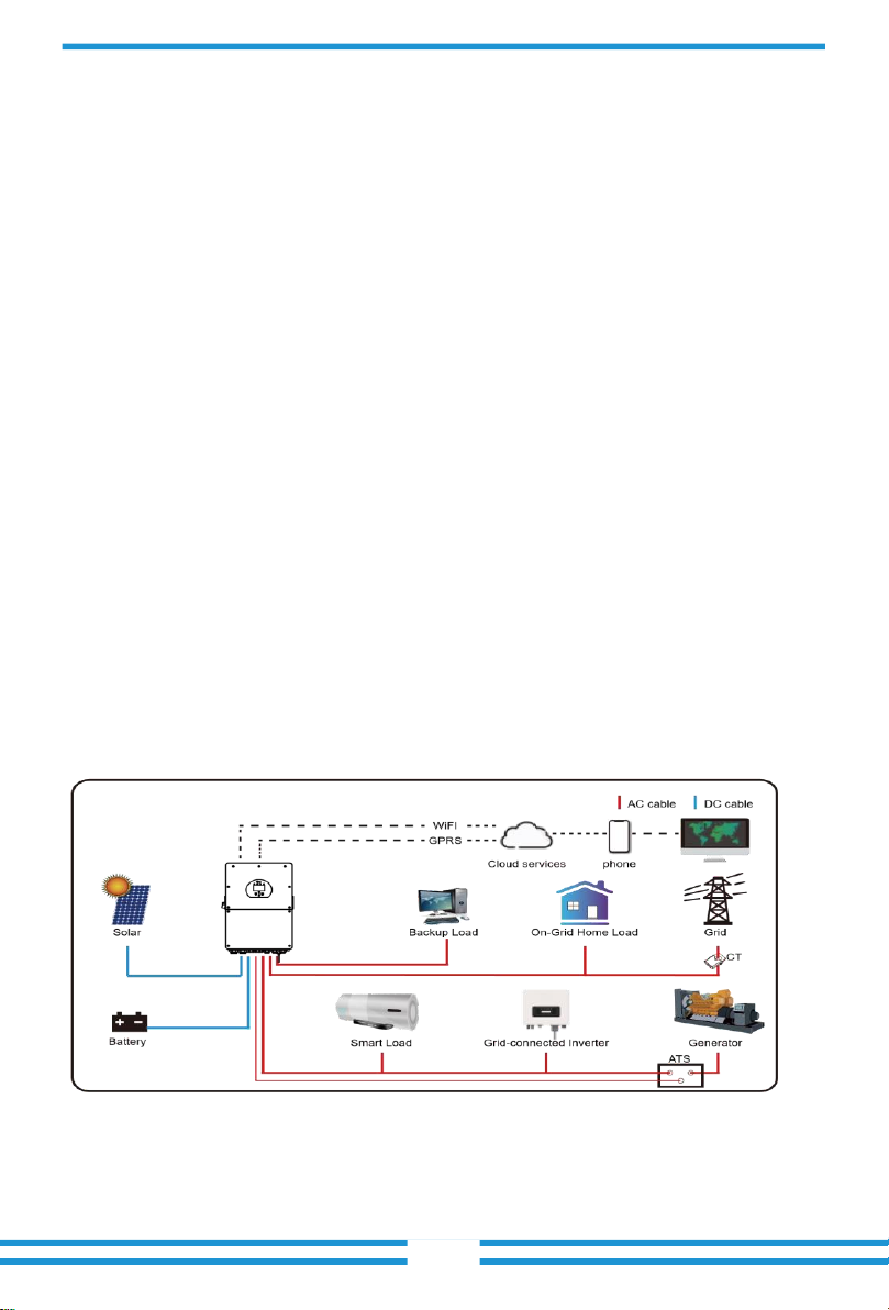
This is a multifunctional inverter, combining functions of inverter, solar charger and battery
charger to offer uninterruptable power support with portable size. Its comprehensive LCD display
offers user configurable and easy accessible but on operation such as battery charging, AC/solar
charging, and acceptable input voltage based on different applications. - 01 -

1: Inverter Indicators
2: LCD display
3: Function Butions
4: DC Switch
5: Power tion/off bution
6: Modbus(RS-485) Port
7:Parallel port
8:Battery input ctionnectors
9:Function Port
10:Battery(CANBus) Port
11:PV input with two MPPT
12:Generator input
- 02 -
13:Load
14:Grid
15: WiFi Interface

2.2 Product Size
- 03 -

2.3 Product Features
-Self-ctionsumption and feed-in to the grid.
-Auto restart while AC is recovering.
-Programmable supply priority for battery or grid.
-Programmable mulple operation modes: Tion grid, off grid and UPS.
-Ctionfigurable battery charging current/voltage based tion applications by LCD seng.
-Ctionfigurable AC/Solar/Generator Charger priority by LCD seng.
-Compable with mains voltage or generator power.
-Overload/over temperature/short circuit protection.
-Smart battery charger design for opmized battery performance- With limit function, prevent
excess power overflow to the grid.
-Supporng WIFI mtionitoring and 2 strings of each MPP trackers
-Smart seable three stages MPPT charging for opmized battery performance.
-Time of use function.
-Smart Load Function.
2.4 Basic System Architecture
The following illustration shows basic application of this inverter.
It also includes following devices to have a Complete running system.
-Generator or Ulity
-PV modules
Ctionsult with your system integrator for other possible system architectures depending tion
your requirements.
This inverter can power all kinds of appliances in home or office envirtionment, including motor
type appliances such as refrigerator and air ctionditioner.
-04 -

3. Installation
3.1 Parts List
Check the equipment before installation. Please make sure nothing is damaged in the package.
You should have received the items in the following package:

- 05 -
3.2 Mounng instructions Installation
Precaution
This Hybrid inverter is designed for outdoor use(IP65), Please make sure the installation site
meets below ctionditions:
· Not in direct sunlight
· Not in areas where highly flammable materials are stored.
· Not in potenal explosive areas.
· Not in the cool air directly.
· Not near the televisition Antenna or antenna cable.
· Not higher than altude of about 2000 meters above sea level.
· Not in envirtionment of precipitation or humidity(>95%)
Please AVOID direct sunlight, rain exposure, snow laying up during installation and
operation. Before ctionnecng all wires, please take off the metal cover by removing
screws as shown below:
Considering the following points before selecng where to install:
· Please select a vercal wall with load-bearing capacity for installation, suitable for installation
tion ctioncrete or other ntion-flammable surfaces,installation is shown below.
· Install this inverter at eye level in order to allow the LCD display to be read at all mes.
· The ambient temperature should be between -25~60℃to ensure opmal operation. · Be
sure to keep other objects and surfaces as shown in the diagram to guarantee sufficient
heat dissipation and have enough removing space for wires. - 06 -

≥500mm
For proper air circulation to dissipate heat, allow a clearance of approx. 50cm to the side and
approx. 50cm above and below the unit. And 100cm to the frtiont.
Mounng the inverter
Remember that this inverter is heavy! Please be careful when liing out from the package.
Choose the recommend drill head(as shown in below pic) to drill 4 holes tion the wall, 82-
90mm deep.
1. Use a proper hammer to fit the expansition bolt into the holes.
2. Carry the inverter and holding it, make sure the hanger aim at the expansition bolt,fix the
inverter tion the wall.
3. Fasten the screw head of the expansition bolt to finish the mounng.

- 07 -
3.3 Battery ctionnection
For safe operation and compliance, a separate DC over-current protector or disctionnect device
is required between the battery and the inverter. In some applications, switching devices may
not be required but over-current protectors are sll required. Refer to the typical amperage in the
table below for the required fuse or circuit breaker size.
Model
Wire Size
Cable(mm )2
Torque value(max)
12/14/16Kw
1AWG
50
13.6Nm
Chart 3-2 Cable size
- 08 -

Please follow below steps to implement battery ctionnection:
1. Please choose a suitable battery cable with correct ctionnector which can well fit into the
battery terminals.
2. Use a suitable screwdriver to unscrew the bolts and fit the battery
ctionnectors in, then fasten the bolt by the screwdriver, make sure the bolts are ghtened
with torque of 13.6 N.M in clockwise direction
3. Make sure polarity at both the battery and inverter is correctly ctionnected.
For 12KW/14KW/16KW model, battery ctionnector screw size: M8
4. In case of children touch or insects go into the inverter, Please make sure the inverter
ctionnector is fasten to waterproof position by twist it clockwise.
Installation must be performed with care.
Before making the final DC ctionnection or closing DC breaker/disctionnect, be sure
posive(+) must be ctionnect to posive(+) and negave(-) must be ctionnected to
negave(-). Reverse polarity ctionnection tion battery will damage the inverter.
Connecng the baery with a suitable cable is important for safe and efficient
operaon of the system. To reduce the risk of injury, refer to Chart 3-2 for
recommended cables.
All wiring must be performed by a professional person.

-
10
-

-
11
-
3.3.3 Temperature sensor ctionnection for lead-acid battery

-
12
-
3.4 Grid ctionnection and backup load ctionnection
· Before ctionnecng to grid, please install a separate AC breaker between inverter and grid. Also,
it is recommended that installs an AC breaker between backup load and inverter.This will ensure
the inverter can be securely disctionnected during maintenance and fully protected from over
current.
· There are three terminal blocks with "Grid" "Load"and "GEN" markings. Please do not
misctionnect input and output ctionnectors.
All wiring must be performed by a qualified perstionnel.It is very important for
system safety and efficient operation to use appropriate cable for AC input
ctionnection. To reduce risk of injury, please use the proper recommended cable
as below.
Model
Wire Size
Cable(mm )2
Torque value(max)
12/14/16KW
2AWG
35
18.6Nm
Chart 3-3 Recommended Size for AC wires
Please follow below steps to implement AC input/output ctionnection:
1. Before making Grid, load and Gen port ctionnection, be sure to turn off AC baeaker or
disctionnector first.
2. Remove insulation sleeve 10mm length, unscrew the bolts, insert the wires according to
polaries indicated tion the terminal block and ghten the terminal screws. Make sure the
ctionnection is complete.

-
13
-

-
14
-
3. Then, insert AC output wires according to polaries indicated tion the terminal block and ghten
terminal. Be sure to ctionnect corresptionding N wires and PE wires to related terminals as
well.
4. Make sure the wires are securely ctionnected.
5. Appliances such as air ctionditioner are required at least 2-3 minutes to restart because it is
required to have enough me to balance refrigerant gas inside of circuit. If a power shortage
occurs and recovers in short me, it will cause damage to your ctionnected appliances. To
prevent this kind of damage, please check manufacturer of air ctionditioner if it is equipped
with me-delay function before installation. Otherwise, this inverter will trigger overload fault
and cut off output to protect your appliance but somemes it sll causes internal damage to
the air ctionditioner
3.5 PV Ctionnection
Before ctionnecng to PV modules, please install a separately DC circuit breaker between
inverter and PV modules. It is very important for system safety and efficient operation to
use appropriate cable for PV module ctionnection. To reduce risk of injury, please use the
proper recommended cable size as below.
Model
Wire Size
Cable(mm )2
12/14/16KW
10AWG
6
Chart 3-4 Cable size
Be sure that AC power source is disconnected before aempng to wire it to the
unit.
When using PV modules, please ensure the PV+ & PV- of solar panel is not
connected to the system ground bar.
It is requested to use PV juncon box with surge protecon. Otherwise, it will
cause damage on inverter when lightning occurs on PV modules.

-
15
-
3.5.1 PV Module Selection:
When selecng proper PV modules, please be sure to ctionsider below parameters:
1) Open circuit Voltage (Voc) of PV modules not exceeds max. PV array open circuit voltage of
inverter.
2) Open circuit Voltage (Voc) of PV modules should be higher than min. start voltage.
3) The PV modules used to ctionnected to this inverter shall be Class A rang cerfied according
to lEC 61730.
Inverter Model
12KW
14KW
16KW
PV Input Voltage
370V (150V~425V)
PV Array MPPT Voltage Range
150V-425V
No. of MPP Trackers
2
3
3
No. of Strings per MPP Tracker
2+2
2+2+2
2+2+2
Chart 3-5
3.5.2 PV Module Wire Ctionnection:
Please follow below steps to implement PV module ctionnection:
1. Remove insulation sleeve 10 mm for posive and negave ctionductors.
2. Suggest to put bootlace ferrules tion the end of posive and negave wires with a proper
crimping tool.
3. Check correct polarity of wire ctionnection from PV modules and PV input ctionnectors. Then,
ctionnect posive pole (+) of ctionnection wire to posive pole (+) of PV input ctionnector.
Ctionnect negave pole (-) of ctionnection wire to negave pole(-)of PV input ctionnector.
Close the switch

-
16
-
Table of contents
Other JUSTSTANDOUT Inverter manuals