EverFocus ESM308T000D User manual

GIGABIT MANAGED
ETHERNET SWITCH
8 P
o
E+ PORTS
USER MANUAL
Part #ESM308T000D
ESM308T000D

2
INTRODUCTION
This handy switch is designed to pass both data and electrical power to a number
of PoE-compatible devices via standard Cat5e or Cat6 network cables.
Easy-to-follow instructions in this user manual help make installation quick and
simple, so you’ll also soon be enjoying the benets of these additional features:
• 10/100/1000 auto-sensing ports automatically detect optimal network speeds
• IEEE 802.3at/af-compliant RJ45 PoE/PoE+ output ports
• Power output up to 30 Watts per port*
• Total power budget of 130 Watts
• Supports IEEE 802.3at and IEEE 802.3af-compliant PoE devices (wireless
access points, VoIP phones, IP cameras)
• Supports IEEE 802.3at/af detection and short circuit, overload and high-voltage
protection
• All RJ45 ports with Auto-MDIX (auto uplink) support
• Web-based conguration
• Provides detailed trafc and power use statistics
• Supports SNMP management
• Supports VLAN (tag-based and port-based)
• Provides IEEE 802.1x port-based security
• Supports link aggregation (trunking)
• Supports port mirroring
• Supports two types of QoS: 802.1p and DSCP
• Broadcast storm control with multicast packet rate settings
• Store and forward switching architecture
• Supports jumbo frames up to 9.6 kBytes
• Supports Rapid Spanning Tree/Spanning Tree protocol
• IEEE 802.3x ow control for full duplex
• Supports up to 8192 MAC address entries
• 176 kBytes buffer memory
• Desktop-size metal case
* Total PoE budget for this switch is 130 watts. Per-port average power distribution
is 15 Watts; maximum per-port power usage cannot exceed 30 Watts.
Some of the following screen images have been modied to t the format of this
user manual.
NOTE: For a quick install procedure, refer to the quick install guide enclosed with
this product.

3
CONTENTS
CONTENTS
CONNECTIONS & INDICATORS .........................................................................5
LEDs ..............................................................................................................5
Ports ..............................................................................................................5
Power ..............................................................................................................5
WEB-BASED BROWSER MANAGEMENT .........................................................6
Login ..............................................................................................................6
Conguration ...................................................................................................6
System ...................................................................................................6
Ports.......................................................................................................9
VLANs ..................................................................................................10
Aggregation..........................................................................................13
LACP....................................................................................................13
RSTP....................................................................................................14
IGMP Snooping....................................................................................15
Mirroring ...............................................................................................16
Quality of Service (QoS) ......................................................................17
Power over Ethernet (PoE) ..................................................................19
Storm Control .......................................................................................20
Monitoring......................................................................................................21
Statistics Overview...............................................................................21
Detailed Statistics.................................................................................21
LACP Status.........................................................................................21
RSTP Status ........................................................................................22
IGMP Status.........................................................................................24
VeriPHY................................................................................................24
Ping ......................................................................................................25
Maintenance..................................................................................................25
Reboot..................................................................................................26
Factory Default.....................................................................................26
Software Upload...................................................................................26
Conguration File Transfer...................................................................26
Logout ..................................................................................................26
SPECIFICATIONS...............................................................................................27

4
REGULATO RY STATEMENTS
SAFETY & COMPLIANCE STATEMENTS
FEDERAL COMMUNICATIONS COMMISSION (FCC) STATEMENT
This equipment has been tested and found to comply with the limits for a Class A
digital device, pursuant to part 15 of the FCC Rules. These limits are designed to
provide reasonable protection against harmful interference when the equipment is
operated in a commercial environment. This equipment generates, uses and can
radiate radio frequency energy and, if not installed and used in accordance with
the instruction manual, may cause harmful interference to radio communications.
Operation of this equipment in a residential area is likely to cause harmful
interference, in which case the user will be required to correct the interference at
his own expense.
This device complies with Part 15 of the FCC Rules. Operation is subject to the
following two conditions: 1) This device may not cause harmful interference and 2)
This device must accept any interference received, including interference that may
cause undesired operation.
CE STATEMENT
This equipment complies with the requirements relating to electromagnetic
compatibility, EN 55022 class A for ITE, the essential protection requirement of
Council Directive 89/336/EEC on the approximation of the laws of the member
states relating to electromagnetic compatibility.
INSTALLATION TIPS
As with any electrical device, you should place the switch where it will not be
subjected to extreme temperatures, humidity or electromagnetic interference:
• Place the switch on a level surface with at least 25 mm (approx. 1”) of clearance
for ventilation;
• The ambient temperature should be between 32 and 104 degrees Fahrenheit
(0 to 40 degrees Celsius).
• The relative humidity should be less than 90 percent, non-condensing.
• Surrounding electrical devices should not exceed the electromagnetic eld (RFC)
standards for IEC 801-3, Level 2 (3V/M) eld stength.
• Make sure that the switch receives adequate ventilation. Do not block the fan
exhaust port on the switch.
• The power outlet should be within 1.5 meters of the switch.
• Do not place objects on top of the unit.
• Always avoid dust and dirt.

5
CONNECTIONS & INDICATORS
LEDs
The LED indicators — Power,
PoE, Link/Activity — make it
easier to monitor the switch and
its connections.
Ports
All ports on the switch support Auto-MDI/MDI-X functionality, so crossover cables
and uplink ports are not needed for connections to PCs, routers, hubs, other
switches, etc. Cat5/5e/6 UTP/STP cables provide optimal performance; if a status
LED doesn’t indicate a link or activity, check the corresponding device for proper
setup and operation. NOTE: The recessed Reset button can be pressed (using a
pin or similar pointed object) to reset the switch if it isn’t responding.
Power
Use the included power cord to connect the device (next to
the On/Off switch on the rear panel) to an AC outlet. Conrm
that the power LED on the front panel is lit.
ON
OFF
LED Status Operation
Power On Power on
Off Check the AC connection; turn the power on
PoE
On Port
is linked to a PSE/PoE device
Off No
PSE/PoE device is linked
Link/Act On Valid port connection
Blinking Valid port connection; data transmitted/received
Off No link established

6
WEB-BASED BROWSER MANAGEMENT
You can set up and manage the switch remotely by connecting it to a computer
with Ethernet cable and using the switch’s Web-based browser management inter-
face.
Log In
The advanced management capabilities of the switch can be accessed using a
standard Internet browser. To access the Web-based management interface:
1. Activate your Web browser and enter the IP address
192.168.1.1 in the address eld.
2. When the Login screen displays, enter “admin” in the
Password eld, then click Apply. The message
“Password Successfully Entered” displays to indicate
the login is complete, and the main menu screen
displays on the right side of the screen. Click on the links —
grouped under Conguration, Monitoring and Maintenance —
to access the various management functions.
Conguration
The Conguration menu features the following subsections: System, Ports, VLAN,
Aggregation, LACP, RSTP, IGMP Snooping, Mirroring, QoS (Quality of Service),
PoE (Power over Ethernet) and Storm Control.
System
This screen provides system conguration information and the current status of the
device. Click Apply so any changes that are made will take effect.
MAC Address: Displays the unique hardware address assigned by manufacturer
(default).
S/W Version: This is the software version of this device.
H/W Version: This is the hardware version of this device.
Active IP Address: Displays the current effective IP address of the device.
Active Subnet Mask: Displays the current effective subnet mask of the device.
Active Gateway: Displays the current effective gateway of the device.
DHCP Server: If the device uses the DHCP server to connect to the network, the
system will display the IP address of the DHCP server. The default value is
0.0.0.0, indicating the DHCP is disabled.
Lease Time Left: Displays the real remaining lease time to the DHCP server.
DHCP Enabled: Either enabled (checked) or disabled (default). Species whether

7
WEB-BASED BROWSER MANAGEMENT
the IP address is static or dynamically assigned via DHCP. “Enabled” is a
special case of a dynamically assigned IP address. DHCP is widely used in LAN
environments to dynamically assign IP addresses from a centralized server,
which reduces the overhead of administrating IP addresses.
Fallback IP Address: XXX.XXX.XXX.XXX, where XXX ranges from 0 to 255.
Default: 192.168.1.1. Species the IP address of this device. An IP address is
a 32-bit number that is notated by using four segments of numbers, each from 0
through 255, separated by periods. Only a unicast IP address is allowed, which
ranges from 1.0.0.0 to 233.255.255.255.

8
WEB-BASED BROWSER MANAGEMENT
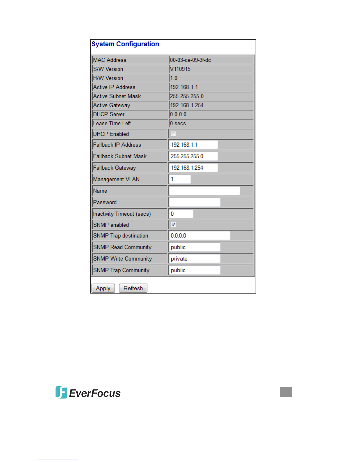
Fallback Subnet Mask: XXX.XXX.XXX.XXX, where XXX ranges from 0 to 255.
Default: 255.255.255.0. Species the IP subnet mask of this device. An IP
subnet mask is a 32-bit number that is notated by using four numbers from 0
through 255, separated by periods. Typically, subnet mask numbers use either
0 or 255 as values (e.g., 255.255.255.0), but other numbers can appear.
Fallback Gateway: XXX.XXX.XXX.XXX, where XXX ranges from 0 to 255.
Default: 0.0.0.0. Species the default gateway IP address. It is only required
if you intend to manage the device from another LAN connected via an IP router.
The gateway address must be on the same IP subnet as this device.
NOTE: After applying a new IP address, a new login page will automatically
appear. Log in again to proceed to other congurations.
Management VLAN: The number ranges from 1 to 4094. Default: 1. Modify this
parameter with care! It species the VLAN through which the switch can be
managed. By default, the switch is programmed to use VLAN 1 for management
and every port on the switch is programmed to use VLAN 1. If you modify a
switch port to use a VLAN other than the management VLAN, devices on that
port will not be able to manage the switch. If you change the management VLAN
without having at least one port that supports the new management VLAN
number, you will lose the ability to contact the management package. The
switch will immediately stop responding to any pings, TFTP, Telnet and Web
sessions from the old management VLAN. For this reason, it’s suggested that
modication of VLAN management information be made early in the switch-
commissioning process, and via the console port.
Name: 16-character ASCII string. Default: admin. The system name can make it
easier to identify the switches within your network provided that all switches are
given a unique name.
Password: 16-character ASCII string. Default: admin. From here, you can modify
the default management password.
Inactivity Timeout (secs): 0 or 60 to 10000. Default: 0. Species when
the console will time out and display the login screen if there is no user activity.
A value of zero disables timeouts for console users. For console users, the
maximum timeout value is limited to 10,000 seconds.
SNMP Enabled: Either Enabled or Disabled (default). This parameter enables or
disables SNMP access to the device. The device supports Simple Network
Management Protocol Version 1 and Version 2 (SNMPv1 and SNMPv2), which
provide access to devices over the network.
SNMP Trap Destination: XXX.XXX.XXX.XXX, where XXX ranges from 0 to 255.
Default: 0.0.0.0. This is the IP address of the user’s SNMP management station
if it is congured to receive traps and notications.
SNMP Read Community: Any 20 characters. Default: public. This parameter
identies the MIB tree(s) to which this entry authorizes read access.

9
WEB-BASED BROWSER MANAGEMENT
SNMP Write Community: Any 20 characters. Default: private. This parameter
identies the MIB tree(s) to which this entry authorizes write access.
SNMP Trap Community: Any 20 characters. Default: public. This parameter
identies the MIB tree(s) to which this entry authorizes access for notications.
Ports
The settings on these screens — including Mode and Flow Control — allow you to
congure the functions of each port, in part so you can limit the number of devices
using a switch port and protect against MAC ooding attacks. Select the port number
and set its functions, then click Apply to save the new settings to the device.
Enable Jumbo Frames: Select/enable to adjust the size of jumbo frames. This
switch provides more efcient throughput for large sequential data transfers by
supporting jumbo frames on Gigabit Ethernet ports up to 9600 bytes. Compared
to standard Ethernet frames that run only up to
1500 bytes
, using jumbo frames
signicantly reduces the per-packet overhead required to process protocol
encapsulation elds.

10
WEB-BASED BROWSER MANAGEMENT
Power Saving Mode: When enabled, it adjusts the power provided to ports based
o
n the length of the cable used to connect to other devices. Only sufcient power
is used to maintain connection requirements.
Link: Displays the current link status of each port: 1000MFDX, 100MFDX,
100MHDX, 10MFDX, 10MHDX or Down. The eld lights green and shows
the link speed if there is a valid connection on the port.
Mode: Options are Auto Speed, 10 Half, 10 Full, 100 Half, 100 Full, 1000 Full
and Disabled. Default: Auto Speed. Enabling auto-negotiation (Auto) results in
speed and duplex being negotiated upon link detection; both end devices must be
auto-negotiation compliant for the best possible results. 10Mbps and 100Mbps
ber optic media don’t support auto-negotiation, so these media must be explicitly
congured to either half or full duplex. Full duplex operation requires that both ends
be congured as such; otherwise, severe frame loss will occur during heavy
network trafc. Auto supports all speed and duplex modes. Disabling a port (for
troubleshooting or to secure it from unauthorized connections, perhaps) will
prevent all frames from being sent and received on that port. Also, when
disabled, link integrity pulses aren’t sent, so the link/activity LED will never be lit.
Flow Control: Either Enabled or Disabled (default). This is useful for preventing
frame loss during times of severe network trafc. Examples of this include
multiple source ports sending to a single destination port or a higher-speed port
bursting to a lower-speed port. When the port is half duplex, it is accomplished
using backpressure, in which the switch simulates collisions, causing the sending
device to retry transmissions according to the Ethernet backoff algorithm. When
the port is full duplex, it is accomplished using PAUSE frame, which causes the
sending device to stop transmitting for a certain period of time.
Drop frames after excessive collisions: Either Enabled or Disabled (default).
Enable to discard the frames after excessive collision.
VLAN
s
A virtual LAN (VLAN) is a logical network grouping that limits the broadcast domain
and allows you to isolate network trafc so only the members of the same VLAN
will receive trafc from others in that same group. Trafc on one VLAN cannot
pass to another except through an intranetwork router or Layer 3 switch. Basically,
creating a VLAN from a switch is logically equivalent to reconnecting a group of
network devices to another Layer 2 switch. However, all the network devices are
still plugged into the same switch physically. A VLAN tag is the identication
information that is present in frames in order to support VLAN operation.
VLAN Port Segmentation
VLAN ID: Enter any number from 1 to 4094 (without leading zeroes); click Add.
VLAN Conguration List: This displays all the current VLAN groups created for

11
WEB-BASED BROWSER MANAGEMENT
this system. Up to 16 VLAN groups can be dened. VLAN 1 is the untagged
default VLAN.
Modify: Click to complete the current VLAN conguration.
Delete: Click to delete the current VLAN conguration.
VLAN Setup
The switch supports up to 16 VLANs based on the 802.1Q standard. From the VLAN
Membership screen you can create and delete VLANs and change the VLAN port
membership.
VLAN Per Port Conguration
This screen lets you change the VLAN parameters for individual ports or trunks. You
can congure VLAN behavior for specic interfaces, including the accepted frame
types and default VLAN identier (PVID). Each row corresponds to one port or trunk.
NOTE: Trunked ports can’t be congured individually, so congure the trunk instead.

12
WEB-BASED BROWSER MANAGEMENT
Port: The number of the port or the ID of a trunk.
VLAN Aware Enabled:
When enabled (default is Disabled), the VLAN-aware ports
are able to use VLAN tagged frames to determine the destination VLAN of a
frame. VLAN-aware ports will strip the VLAN tag from received frames and
insert the tag in transmitted frames (except for the PVID). VLAN-unaware ports
will not strip the tag from received frames or insert the tag in transmitted frames.
Ingress Filtering Enabled: When enabled (default is Disabled), incoming frames
for VLANs which do not include this ingress port in their member set will be
discarded.
Packet Type:
This sets the interface to accept all frame types: select All to include
tagged or untagged frames; select Tagged Only to limit acceptence only to
tagged frames. (Default: All.) When set to All, the port can accept incoming
tagged and untagged packets. Any received packets that are untagged are
assigned to the default VLAN. Any tagged packets will be dropped unless the
port is a member of the VLAN identied by the VLAN tag in the packet. When
set to Tagged Only, the port will drop untagged packets and only receive tagged
packets. Tagged packets will be dropped unless the port is a member of the
VLAN identied by the VLAN tag in the packet. Switches should be connected
to each other with the Packet Type set to Tagged Only.
PVID: The PVID (Port VLAN ID) is associated with untagged, ingress packets. It’s
assigned to untagged frames received on the specied interface. The PVID has
no effect on ports that have Packet Type set to Tagged Only. (Default PVID: 1.)
It is not possible to remove a port from VLAN 1 unless its PVID has been
changed to something other than 1. Outgoing packets are tagged unless the
packet’s VLAN ID is the same as the PVID. When the PVID is set to None
(recommended as the standard conguration option in Tagged Only mode), all
outgoing packets are tagged.

13
WEB-BASED BROWSER MANAGEMENT
Aggregation
This screen lets you create port trunks so multiple links can be bundled to act as a
single physical link for increased throughput, providing load balancing and redundancy
of links in a switched inter-network. Actually, the link doesn’t have an inherent total
bandwidth equal to the sum of its component physical links. Trafc in a trunk is
distributed across an individual link in a deterministic method called a hash algorithm,
which automatically applies load balancing to the ports. A port failure within the
trunk group causes the network trafc to be directed to the remaining ports. Load
balancing is maintained whenever a link in a trunk is lost or returned to service.
Aggregation / Trunking Conguration
To assign a port to a trunk, click the required trunk number, then click Apply
.
LACP
The IEEE 802.3ad Link Aggregation Control Protocol (LACP) increases bandwidth
by automatically aggregating several physical links together as a logical trunk and

14
WEB-BASED BROWSER MANAGEMENT
providing load balancing and fault tolerance for uplink connections.
LACP Port Conguration
Port: Indicates the port number to be congured.
Protocol Enabled: Enables LACP on the associated port.
Key Value: Congures a port’s LACP administration key. The port administrative
key must be set to the same value for ports that belong to the same link
aggregation group (LAG). If this administrative key is not set when an LAG is
formed (i.e., it has the null value of 0), this key will automatically be set to the
same value as that used by the LAG.
RSTP
The IEEE 802.1w Rapid Spanning Tree Protocol (RSTP) provides a loop-free
network and redundant links to the core network with rapid convergence to ensure
faster recovery from failed links, enhancing overall network stability and reliability.
RSTP System Conguration
System Priority: Options range from 0to 61440. Default: 32768. This parameter
congures the spanning tree priority globally for this switch. The device with the
highest priority becomes the STP root device. However, if all devices have the
same priority, the device with the lowest MAC address will then become the root
device.
Hello Time: Enter a value from 1 to 10. Default: 2. This is the interval (in seconds)
at which the root device transmits a conguration message (BPDU frame).
Max Age: Enter a value from 6 to 40. Default: 20. This is the maximum time (in
seconds) a device can wait without receiving a conguration message before
attempting to recongure. It also equals the maximum lifetime of a BPDU frame.
Forward Delay: Enter a value from 4 to 30. Default: 15. This is the maximum time
(in seconds) the root device will wait before changing states (i.e., discarding to
learning to forwarding).
Force Version: Select Normal (default) to support only RSTP, or Compatible to
support both STP (802.1d) and RSTP.

15
WEB-BASED BROWSER MANAGEMENT
RSTP Port Conguration
Port: The port ID can’t be changed. “Aggregations” refers to any congured trunk
group.
Protocol Enabled: Click to enable (checked) or disable (default). When checked,
you’re enabling RSTP for this port as per the conguration in the RSTP Port
Conguration menu.
Edge: The default setting is enabled (checked); click to disable (unchecked). Edge
ports don’t participate in the Spanning Tree Protocol, but still send conguration
messages, linking to an end station or another STP device.
Path Cost:
This parameter is used by the STP to determine the best path between
devices. Lower values should be assigned to ports attached to faster media;
higher values for slower media. Set the RSTP pathcost on the port. Enter a
value from 0 to 200000000 or keep the default setting (Auto).
IGMP Snooping
Internet Group Management Protocol (IGMP) Snooping is the process of listening
to IGMP network trafc. As implied by the name, IGMP Snooping is a feature that
allows a Layer 2 switch to “listen in” on the IGMP conversation between hosts and
routers by processing the Layer 3 IGMP packets sent in a multicast network. When
enabled in a switch, IGMP Snooping analyzes all IGMP packets between hosts
connected to the switch and multicast routers in the network. When a switch hears
an IGMP report from a host for a given multicast group, the switch adds the host’s
port number to the multicast list for that group. And when the switch hears an
IGMP “leave,” it removes the host’s port from the table entry. As a result, this
feature prevents ooding of IP multicast trafc and limits bandwidth-intensive video
trafc to subscribers only.

16
WEB-BASED BROWSER MANAGEMENT
IGMP Conguration
IGMP Enabled: When checked/selected, the switch will monitor network trafc to
determine which hosts want to receive multicast trafc.
Router Ports: Select if the port is connecting to the IGMP administrative routers.
Unregistered IPMC Flooding enabled: Select this forwarding mode for
unregistered (not-joined) IP multicast trafc. The trafc will ood when enabled
(checked) and forward to router-ports only when disabled.
IGMP Snooping Enabled: When checked/selected, the port will monitor network
trafc to determine which hosts want to receive the multicast trafc.
IGMP Querying Enabled: When checked/selected, the port can serve as the
querier, responsible for asking hosts if they want to receive multicast trafc.
Mirroring
Port Mirroring is used on a network switch to send a copy of network packets seen
on one switch port (or an entire VLAN) to a network monitoring connection on

17
WEB-BASED BROWSER MANAGEMENT
another switch port. This is commonly used for network appliances that require
monitoring of network trafc, such as an intrusion-detection system.
Mirroring Conguration
Mirror Source: The port that will duplicate, or “mirror,” the trafc on the source port.
Only incoming packets can be mirrored. Packets will be dropped when the
available egress bandwidth is less than the ingress bandwidth.
Mirror Port: Select the ports that you want to mirror, then click Apply.
Quality of Service
Quality of Service (QoS) enhances communication quality by giving precedence to
certain classes of packets. This switch provides QoS Disabled, 802.1p and
DSCP modes.
QoS Conguration
Strict:
Services the egress queues in sequential order, transmitting all trafc in the
higher-priority queues before servicing lower-priority queues.
WRR: Weighted Round-Robin shares bandwidth at the egress ports by using
scheduling weights with default values of 1, 2, 4, 8 for queues 0 through 7,
respectively. (This is the default selection.) NOTE: WRR can only be selected if
Jumbo Frame mode is disabled on the Port Conguration screen.
QoS Mode: 802.1p
Packets are prioritized using the 802.1p eld in the VLAN tag. This eld is three
bits long, representing the values 0 - 7. When the QoS Mode is set to 802.1p, the
802.1p Conguration table appears, allowing you to map each of the eight 802.1p
values to a local priority queue (low, normal, medium or high). The default settings
are shown below.

18
WEB-BASED BROWSER MANAGEMENT
QoS Mode: DSCP
Packets are prioritized using the Differentiated Services Code Point (DSCP) value,
a six-bit eld that is contained within an IP (TCP or UDP) header. The six bits allow
the DSCP eld to take any value in the range 0 - 63. When QoS Mode is set to DSCP,
the DSCP Conguration table is displayed, allowing you to map each of the DSCP
values to a hardware output queue (low, normal, medium or high). The default
settings map all DSCP values to the high-priority egress queue. The Prioritize
Trafc drop-down list lets you quickly set the values in the DSCP Conguration
table to a common priority queue. Select Custom to set each value individually.

19
WEB-BASED BROWSER MANAGEMENT
PoE (Power over Ethernet)
Power over Ethernet (PoE) is deployed in applications where supplying AC power
would be inconvenient, expensive or infeasible. Web Smart features let you

20
WEB-BASED BROWSER MANAGEMENT
remotely control and centralized the power management simply by using a Cat5
cable to deliver both power and data.
PoE Conguration
PoE Enabled: When enabled (checked), you can use the port to supply power to
the attached — and thus, powered — device (PD), which in turn allows you to
remotely access that device and monitor its status.
PD Class: This indicates the PD’s classication (Class 0-4).
Delivering Power (W): This is the port’s output power.
Current (mA): This is the port current.
Voltage (V): This is the port voltage.
Power Budget (%): This is the percentage of power usage.
Storm Control
Broadcast storms can occur when a device on your network is malfunctioning or
if application programs are not well designed or properly congured. If there is too
much broadcast trafc on your network, performance can be severely degraded —
even to the point where everything comes to a complete halt. You can protect your
network from broadcast storms by setting a threshold for broadcast trafc for each
port. Any broadcast packets exceeding the specied threshold will then be dropped.
Storm Control Conguration
There are three types of trafc that can be rate limited: Broadcast Rate, Multicast
Rate and Flooded Unicast Rate.
The Rate eld (number of frames per second) is
set by a single drop-down list since the same threshold is applied to every port on
the switch. In other words — regardless of the ow-control settings — when the
threshold is exceeded, packets are dropped.
Table of contents
Other EverFocus Switch manuals

EverFocus
EverFocus ES0501-40 User manual

EverFocus
EverFocus eNVP-JNN-IV-D0008 User manual

EverFocus
EverFocus EverFocus ES1645-51 User manual

EverFocus
EverFocus ES2446-51 User manual

EverFocus
EverFocus ES1625-31 User manual

EverFocus
EverFocus ESM316T002R User manual

EverFocus
EverFocus ESM316T002R User manual

EverFocus
EverFocus ES2426-31 User manual

EverFocus
EverFocus ES0812-31 User manual
Popular Switch manuals by other brands

INNOVATIVE CIRCUIT TECHNOLOGY
INNOVATIVE CIRCUIT TECHNOLOGY ICT200-LVD instruction manual

Exsys
Exsys EX-1163HMS-WT manual

Renkforce
Renkforce RF-DKS-903 operating instructions

Clas Ohlson
Clas Ohlson 32-4934 quick guide

ANTAIRA
ANTAIRA LNP-2602G-SFP Series Quick installation guide

GALCO
GALCO EX95000 Series quick start guide