Everidge PREPRITE PPT481C Series User manual
PPT481C
PPT602C
PPT843C
PAD7
Series Refrigerated Prep Tables
Operation and Care Manual
For


This appliance is for commercial use only.
To avoid electrical shock, this appliance MUST be adequately grounded in accordance with local electrical codes or, in
the absence of local codes, with the current edition of the national Electrical Code ANSI/NFPA no. 70. In Canada, all
electrical connections are to be made in accordance with CSA C22.1, Canadian Electrical Code Part 1 or local codes.
1. This appliance must be installed on a stable and level surface.
2. DO NOT install this appliance in any area where it may be affected by any adverse conditions such as
steam, grease, dripping water, high temperatures, etc.
3. DO NOT store or use any flammable liquids or allow flammable vapors in the vicinity of this appliance or
any other appliance.
4. This appliance must be kept free and clear of any combustible materials.
5. This appliance must be kept free and clear of any obstructions blocking access for maintenance or
service.
This machine is designed to be only used indoors.
To reduce the risk of electric shock and injury to persons, unplug from the power supply before servicing.
This appliance has parts that can cause pinching and injury. Please ensure that fingers are kept away from these
areas and proper attire is worn.
This appliance is intended for use in commercial establishments where all operators are familiar with the purpose,
limitations, and associated hazards of this appliance. Operating instructions and warnings must be read
and understood by all operators
Warning!
These appliances are heavier than they look and should be moved with proper equipment and personnel.
This appliance must service by qualified service personnel. Failure to properly maintain and service this appliance
can and will cause injury or even death.
1

2
CHAPTER 1
Operation and Care Manual
CHAPTER 3
Warranty
CHAPTER 2
How to use the Operation and Care Manual
Safety precautions and
Manufacturer’s liabilities
Regulatory references
The operation and care manual is a document issued by
the manufacturing company and is an integral part of
the machine. This document is adequately identified for
easy tracing and/or subsequent references.
All rights relating to the reporduction and disclosure of
the information contained in this handbook and the
documentation quoted and/or attached are reserved.
This handbook contains the information necessary for
the customer and assigned personnel, to ensure the
correct installation, use and maintenance of the
appliance allowing it to be used safely.
Disposal of this appliance after its useful life.
Electric and electronic appliances contain dangerous
substances that may have potentially harmful effects
for people and the environment. It is recommended to
dispose of it properly, DO NOT DISPOSE OF ELECTRICAL
OR ELECTRONIC EQUIPMENT WITH OTHER MUNICIPAL
WASTE.
Every operation related to the inteded use of this
appliance and its overall life cycle has been carefully
and thoroughly analyzed by the manufacturing
company during the design phase, construction phase
and the writing of the operation and care manual.
It is nevertheless understood that experience, proper
training and “common sense” of the personnel
operating this appliance are of the utmost importance.
It is the responsibility of the operator to observe all
safety precautions as outlined in this manual and to
operate this appliance accordingly.
This document is an integral part of the machine.
Preserve a copy of this operation manual for the entire
working life of the appliance even if transferred or sold.
Additional copies can be obtained from the
manufacturer.
To maintain the operation and care manual in good
condition:
1. Use the operation and care manual carefully so as to
not damage its contents. In particular, do not leave
the operation and care manual around after use and
return it to its proper place immediately after
consultation.
2. Do not remove, rip out or rewrite parts of the
operation and care manual. Any changes to this manual
are to be issued by the manufacturer.
3. Keep the operation and care manual in a safe place,
away from environmental elements which could
damage it.
The non-observance of the safety precautions or
specific warnings indicated in this manual, the use of
this appliance by unauthorized personnel, violation of
all safety standards regarding the design, construction,
and intended use of the machine, will relieve the
manufacturer from all liability in the case of damage to
personnel or peroperty.
The manufacturing company is therefore in no way
responsible for the non-observance on the part of the
user of the safety precautions listed in the manual.
PrepRite warrants to the original purchaser only
that any original part that is found to be defective in
material or workmanship will, at PrepRite’s option,
subjet to provisions hereinafter stated, be replaced
with a new or rebuilt part. For all other original parts,
twenty four (24) months from the date of shipment of
appliance. The labor warranty period is twenty four (24)
months from the shipping date. PrepRite will bear
normal labor charges performed during standard
business hours, excluding overtime, holiday rates or any
additional fees. To be valid, a warranty claim must be
filed during the applicable warranty period. This
warranty is not transferable
1. All machine components normally subject to wear
and are considered consumables are not included in the
warranty: door gaskets, rubber casters, air filter.
The following manual CONFORMS TO ANSI/UL Std. 471-
CERT. TO CAN/CSA Std.C22.2 No. 120 - CONFORMS TO
NSF 7

3
CHAPTER 4
General Safety Precautions
End User Obligations
The end user must immediately inform the
manufacturer of any safety system defect and/or any
malfunction he or she is aware of.
It is strictly forbidden for the end user and/or any third
parties (excluding duly authorized service personnel of
the manufacturer) to make modifications of any kind to
the appliance, its functions or to this technical
publication. In case of malfunctions or defects due to
the non-observance of the above, the manufacturing
compnay cannot be held responsible for the
consequences.
End User Obligations
1. Never touch the metal parts of the machine with wet
or damp hands;
2. Do not pull on the cord to disconnect the plug from the
current outlet.
3. Unqualified or untrained personnel are not allowed
to use the machine without supervision.
4. Electrical safety of the machine is ensured by a
properly grounded electrical circuit, which consists of a
grounded cord and cord cap and a correct electrical outlet.
5. The use of an extension cord is not allowed and may
result in injury or death.
6. In the event of damage to the cord, the end user of
the appliance must not attempt to replace the part. This
must be performed by a qualified service personnel.
7. Always switch off and disconnect the appliance from
the power supply before begnning any general cleaning
or maintenance operation.
8. Clean appliance coating, panels and controls using
soft and dry cloths, or cloths slightly soaked in mild
detergent solution.
2. Possible conditions causing electronic controls to fail
include incorrect electrical supply, environmental
elements, storms, lightning, water damage, could cause
damages which cannot be attributed to the
manufacturing company and to the manufacture
of the product itself.
3. During the warranty period, for any defect in
workmanship and material, all parts and labor will be
covered. All warranty claims must be submitted to and
conform by all statements and policies of the
Everidge 24/7 Warranty Service.
4. During the warranty period, we will pay, not to
exceed, one (1) hour travel and fifty (50) miles travel. All
warranty service will be performed by an authorized
service center certified by the manufacturer. All parts
replaced under warranty must be returned to the
manufacturer for inspection before any warranty is
paid.
5. Any components considered defective (door gasket,
electronic control, etc.) and is determined to be caused
by misuse or abuse during the warranty period will not
be considered under warranty. The end user will be
responsible for any repairs or parts for repairs.
6. Equipment modified in any manner from original
model, substitution of parts other than factory
authorized parts, removal of any parts including legs, or
addition of any parts.
7. Any losses or damage resulting from malfunction,
including loss of product, food product, revenue, or
consequential or incidental damages of any kind.
8. Equipment damage caused by accident, shipping,
improper installation or alteration.
9. Any injury caused by failure to abide by these written
instructions, improper installation, improper electrical
connections, alteration to equipment will be the
responsibility of the owner.
10. This warranty is exclusive and is in lieu of all other
warranties, express or implied, including the implied
warranties of merchantability and fitness for a
particular purpose. In no event shall PrepRite be
liable for loss of use, loss of revenue or profit, or loss of
product, or for any indirect, special, incidental, or
consequential damages. No person except an officer of
PrepRite is authorized to modify this warranty or to
incur on behalf of PrepRite any other obligation or
liability in connection with PrepRite equipment.

4
CHAPTER 5
Installation
Warning!
Location
Carefully remove the appliance from the carton or
crate. Note: Do not discard the carton and other
packaging material until you have inspected the unit for
hidden damage and tested it for proper operation.
To ensure proper operation of this appliance and its
components, this appliance must be installed on a
stable and level surface, away from high humidity items
and excesive heat producing equipment.
DO NOT store or use any flammable liquids or allow
flammable vapors in the vicinity of this appliance or
any other appliance.
DO NOT install this appliance in any area where it may
be affected by any adverse conditions such as steam,
grease, dripping water, high temperatures, etc.
Disconnect the appliance from power before
peformning any service or maintenance operation which
may require parts. This appliance must be grounded
properly. If the ground prong is broken, do not use the
appliance until it has been repaired or serious injury
or death may occur.
These appliances require a dedicated circuit and cannot
be plugged into a receptacle that is shared by another
appliance or damage to compressor, blown fuses or
tripped circuits will be caused, which will not be covered
under warranty.
This appliance must have adequate ventilation space to
allow heat to be dissipated from the condenser, as well
as it needs adequate ventilation to cool the condenser.
Do not locate this appliace tight against the wall or
against any heat producing device or damage can occur
to the unit. Please allow a minimum or 2” air gap from
the back and sides and 12” from the front for adequate
ventilation. In locations with excessive dust, dirt, loose
paper, flour or powdery substances, cleaning of the
condenser coil may need to be performed on a fairly
regular basis. This is the customer’s responsibility and
must be performed by a qualified service technician or
damage to the components can and will occur. Do not
use caustic cleaners n the condenser coil as it may
cause leaks to the sealed system.
These appliances are heavy and can be easily damaged
if not removed from the skid correctly. DO NOT
ATTEMPT to remove this appliance from the skid by
pulling it off or Extreme damage will be caused to the
base and casters, which will not be covered under
warranty. Use the proper lifting equipment and protect
the base from damage while lifting appliance from the
skid. Do not drop appliance on its base or extreme
damage will occur.

5
CHAPTER 6
Understanding the Control
Operation
Cleaning and Maintenance
Actual Temperature F or C
Power Button
Manual Defrost Switch
Optional Light Switch
Raise Temperature Set Temperature Lower Temperature
Cooling Indicator
Fan on Indicator
Connect the plug to the proper outlet. If it is not the correct outlet, the outlet must be replaced with the
correct one by a qualified electrician, as well as ensuring the fuse or breaker is the correct current capacity for
the draw of the appliance. Do not use adapters, multiple outlets and/or extension cords. Do not plug in
multiple appliances in the same outlet that may exceed current capacity.
Use mild cleaning products, such as dish detergent or Pine Sol to clen the unit. Do not use any scouring pads
or nylon scrubbers, as this will scratch the surface. Do not flood the compartment with water or use a hose or
pressure washer to clean the interior or exterior of the unit, as extreme damage will occur. The use of a
stainless steel cleaner and polish can be used on the exterior only.
Ensure the door gaskets are kept clean and if they are ripped or damaged, they must be replaced to maintain
proper operation.
1. Turn the unit on by pushing the control on by pushing and holdin the power switch for 2 seconds.
2. To set the cabinet temperature, press the set switch and then using the up or down buttons until the
desired setting is reached, push the set button again.
3. The compressor has a 1 minute delay before it comes on.
4. Once the evaporator coil has reached 40 degrees, the fan(s) will be activated and the cabinet will begin
to cool.
5. Allow the cabinet to pre-cool for at least 1 hour before loading in product. If the product is at ambient
temperature, the cabinet temperature will rise and it may take a couple of hours to stabilize.
6. Once the temperature inside the cabinet reaches the set temperature, the cooling indicator light will
go out, but the fans will continue to run. When the temperature rises, the cooling indicator will turn
back on and the compressor will activate to bring the temperature back down to the set point.
7. Do not keep the door(s) open for an extended period of time, as this will cause the temperature to rise
rapidly and product will not maintain temperature.
8. To turn the unit off, push and hold the power switch for 2 seconds.

6
PPT481C Series Prep Table
Model: PPT481C-4823
• Refrigerated Cabinet
• 2 Drawers
• Ambient Dough Drawers
• Granite Top Asy
• 60” Condiment Rail
Model: PPT481C-4822
• Refrigerated Cabinet
• 1 Door
• Ambient Dough Drawers
• Granite Top Asy
• 60” Condiment Rail
Model: PPT481C-4819
• Refrigerated Cabinet
• 2 Drawers
• Ambient Dough Drawers
• Stainless Steel Top (no sides)
Model: PPT481C-4813
• Refrigerated Cabinet
• 1 Door
• Ambient Dough Drawers
• Granite Top Asy
Model: PPT481C-4815
• Refrigerated Cabinet
• 1 Door
• Ambient Dough Drawers
• Granite Top Asy
Model: PPT481C-4818
• Refrigerated Cabinet
• 2 Drawers
• Ambient Dough Drawers
• Granite Top Asy
Model: PPT481C-4804
• Refrigerated Cabinet
• 1 Door
• Stainless Steel Top (no sides)
Model: PPT481C-4803
• Refrigerated Cabinet
• 1 Door
• Granite Top Asy
Model: PPT481C-4800
• Refrigerated Cabinet
• No Door
• No Top
Model: PPT481C-4809
• Refrigerated Cabinet
• 2 Drawers
• Stainless Steel Top (no sides)
Model: PPT481C-4808
• Refrigerated Cabinet
• 2 Drawers
• Granite Top Asy
Model: PPT481C-4805
• Refrigerated Cabinet
• 1 Door
• Stainless Steel Top

7
PPT602C Series Prep Table
Model: PPT602C-6013
• Refrigerated Cabinet
• 4 Drawers
• Granite Top Asy
Model: PPT602C-6010
• Refrigerated Cabinet
• 1 Door
• 2 Drawers
• Stainless Steel Top Asy
Model: PPT602C-6009
• Refrigerated Cabinet
• 1 Door
• 2 Drawers
• Stainless Steel Top (no sides)
Model: PPT602C-6008
• Refrigerated Cabinet
• 1 Door
• 2 Drawers
• Granite Top Asy
Model: PPT602C-6006
• Refrigerated Cabinet
• 1 Door
• 2 Drawers
• Stainless Steel Top (no sides)
Model: PPT602C-6006
• Refrigerated Cabinet
• 2 Doors
• Granite Top Asy
Model: PPT602C-6001
• Refrigerated Cabinet
• 2 Doors
• No Top
Model: PPT602C-6035
• Refrigerated Cabinet
• 1 Door
• 2 Drawers
• Ambient Dough Drawers
• Granite Top Asy
• 84” Condiment Rail
Model: PPT602C-6023
• Refrigerated Cabinet
• 1 Door
• 2 Drawers
• Ambient Dough Drawers
• Stainless Steel Top
Model: PPT602C-6022
• Refrigerated Cabinet
• 1 Door
• 2 Drawers
• Ambient Dough Drawers
• Granite Top (no sides)
Model: PPT602C-6022
• Refrigerated Cabinet
• 1 Door
• 2 Drawers
• Granite Top Asy
• 60” Condiment Rail
Model: PPT602C-6018
• Refrigerated Cabinet
• 2 Door
• Ambient Dough Drawers
• Granite Top Asy

8
PPT843C Series Prep Table
Model: PPT843C-8409
• Refrigerated Cabinet
• 2 Doors
• 2 Drawers
• Stainless Steel Top
Model: PPT843C-8406
• Refrigerated Cabinet
• 2 Doors
• 2 Drawers
• Undercounter / No Top
Model: PPT843C-8405
• Refrigerated Cabinet
• 3 Doors
• Stainless Steel Top
Model: PPT843C-8403
• Refrigerated Cabinet
• 3 Doors
• Granite Top Asy
Model: PPT843C-8401
• Refrigerated Cabinet
• 3 Doors
• Undercounter / No Top
Model: PPT843C-8420
• Refrigerated Cabinet
• 2 Doors
• 2 Drawers
• Granite Top Asy
• 84” Condiment Rail
Model: PPT843C-8419
• Refrigerated Cabinet
• 3 Doors
• Granite Top Asy
• 84” Condiment Rail
Model: PPT843C-8413
• Refrigerated Cabinet
• 1 Door
• 4 Drawers
• Granite Top Asy
Model: PPT843C-8415
• Refrigerated Cabinet
• 1 Door
• 4 Drawers
• Stainless Steel Top
Model: PPT843C-8418
• Refrigerated Cabinet
• 6 Drawers
• Stainless Steel Top

9
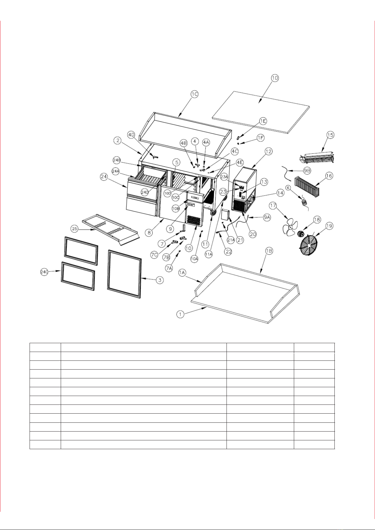
PPT481C Exploded Views
Number
1Granite Table Top CT-3001 1
2
2
2
4
8
1
1
1
1
1
1
1
1
1
CT-3002
CT-3003
CT-3004
CT-3005
BK-2001
SC-100005
SC-100001
SC-100006
CH-3006
GS-7001
HG-8005
HG-8002
HG-8004
HG-8001
Granite Table Top Side Splash
Granite Table Top Back Splash
Stainless Steel Countertop w/ splash (Optional)
Stainless Steel CountertopFlat (Optional)
Stainless Steel Countertop Mounting Brackets
Countertop Mounting Bracket Screws
Cabinet Body
Door Gasket
Upper Door Hinge Left Head
Upper Door Hinge Bearing
Upper Door Hinge Screw
Upper Door Hinge Insert
Upper Door Hinge Right Hand
Upper Door Hinge Insert Screw
1A
1B
1C
1D
1E
1F
2
3
4
4A
4B
4C
4D
4E
Description Part Number Quantity

10
Drawer Rails
Drawer Gasket (Optional)
Drawer Cartridge Complete (Optional)
Drawer Assembly (Optional)
Drawer Front Panel (Optional)
Fuse Holder 30A
Fuse 20A
Power Cord
Electrical Box Cover
Condenser Coil
Condenser Fan Motor Guard/Holder
Condenser Fan Motor
Condenser Fan Blade
Evaporator Coil
Evaporator Fan Assembly
Compressor Whirlpool FFI12HBX
Terminal Strip
Refrigeration Assembly Complete
Caster, Fixed
Caster, Swivel
Condenser and Control Panel
Condenser Louvered Panel Screw
Condenser Louvered Panel
Evaporator Probe
Controller (EVR234N9)
Lower Door Spring Hinge Screw
Lower Door Spring Hinge
Capillary Tube
Side Rack Assembly SH-100002 1
1
1
1
2
1
2
2
4
2
2
1
1
1
1
1
1
1
1
1
1
1
1
1
1
1
1
1
2
2
1
2
4
1
RE-90001
HG-8002
HG-8003
HG-8006
DR-4001
CN-3007
PR-70002
PR-70001
PR-70003
PR-70004
BK-2001
BK-3008
BK-3009
RE-90002
RE-90003
FN-6001
FN-6002
FN-6003
FN-6004
FN-6005
DR-4003
DR-4002
DR-4004
GS-7003
DR-4005
GU-7002
CD-3010
RE-90005
PN-70005
RE-90004
TM-200001
SC-100004
SC-100006
Door Assembly (No Gasket)
Lower Door Spring Hinge Mounting Bracket Right Hand
Lower Door Spring Hinge Mounting Bracket Left Hand
Condenser Probe
Control Panel
5
6
7
7A
7B
7C
8
9
10
11
11A
12
13
14
15
16
17
18
19
20
21
22
23
23A
24
24A
24B
24C
24D
10A
10B
10C
9A
9B
11
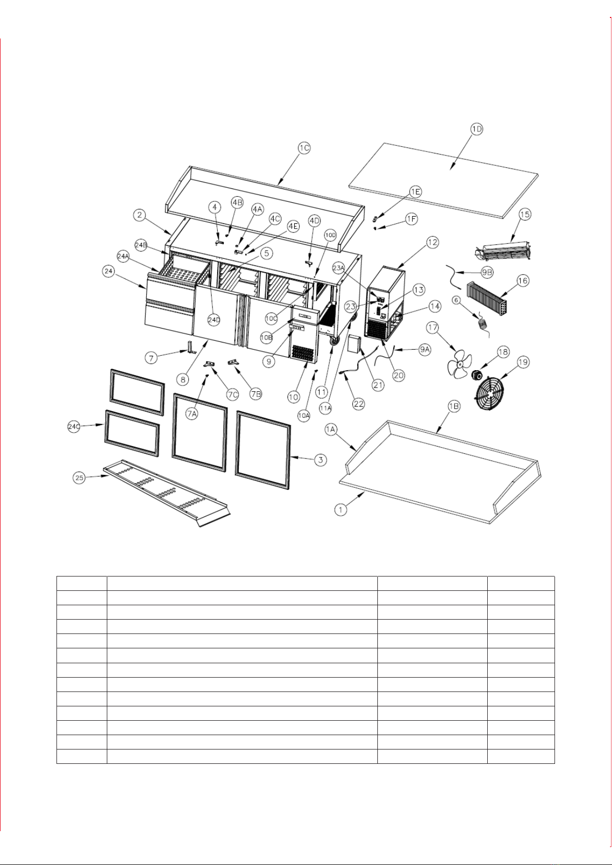
PPT602C Exploded Views
PPT602C Exploded Views
11
Number
1Granite Countertop (Main Flat) CT-3011 1
2
4
8
1
1
2
1
1
2
2
CT-3002
CT-3012
CT-3013
CT-3014
BK-2001
SC-100005
CH-3015
GS-7001
HG-80015
HG-8002
Granite Countertop Side Splash
Granite Countertop Back Splash
Stainless Steel Countertop w/ splash
Stainless Steel Countertop Flat (Optional)
Countertop Mounting Brackets
Countertop Mounting Bracket Screw
Main Chassis
Door Gasket
Upper Door Hinge Left Head
Upper Door Hinge Bearing
1A
1B
1C
1D
1E
1F
2
3
4
4A
Description Part Number Quantity

Drawer Front Panel (Optional)
Fuse Holder
Fuse 20A
Power Cord 16A
Electrical Cover
Conderser Coil
Condenser Motor Mount/Guard
Condenser Fan Motor
Condenser Fan Blade
Evaporator Coil
Evaporator Fan Assembly
Compressor Whirlpool FFI12HBX
Terminal Strip
Refrigeration Assembly Complete
Caster, Fixed
Caster, Swivel
Condenser and Control Panel Bracket
Control Panel
Condenser Louver Panel Screw
Condenser Louver Panel
Evaporator Probe
Controller (EVR234N9)
Door Assembly (No Gasket)
Lower Door Spring Hinge Bracket Right Hand
Lower Door Spring Hinge Screw
Upper Door Hinge Insert Screw
Upper Door Hinge Left Hand
Upper Door Hinge Insert
Upper Door Hinge Screw SH-100001 4
2
2
2
4
1
1
1
2
1
1
2
4
2
2
2
1
4
2
2
1
1
1
1
1
1
1
1
1
1
1
2 or 4
2
HG-8004
HG-8005
SH-100002
RE-90001
HG-8002
SC-100006
HG-8003
HG-8006
DR-4001
PR-70002
PR-70001
PR-70003
SC-100003
PR-70004
CN-3008
CN-3009
TM-200001
RE-90003
GU-7002
RE-90005
PN-70005
CD-3010
FU-6004
FU-6005
DR-4003
GU-6001
FN-6003
RE-90004
FN-6002
RE-90004
BK-2001
CN-3007
SC-100006
Lower Door Spring Hinge
Capillary Tube
Side Rack Assembly
Lower Door Spring Hinge Bracket Right Hand
Condenser Probe
4B
4C
4D
4E
5
6
7
7A
8
10
10A
10B
10C
11
11A
12
13
14
15
16
17
18
19
20
21
22
23
23A
24
Internal Air Baffle
Drawer Rail (Optional)
Drawer Gasket (Optional)
Drawer Cartridge Complete (Optional)
Drawer Assembly (Optional) 2 or 4
1 or 2
2 or 8
1
2 or 4
DR-4002
DR-4004
GS-7003
DR-4005
DN-70006
24A
24B
24C
24D
25
9
9A
9B
7B
7C
12
13
PPT843C Exploded Views
13
Number
1Granite Countertop (Main Flat) CT-3016 1
2
6
4
8
1
1
3
1
1
3
3
CT-3002
CT-3003
CT-3004
CT-3005
BK-2001
SC-100005
SC-100001
CH-3006
GS-7001
HG-8005
HG-8002
Granite Countertop Side Splash
Granite Countertop Back Splash
Stainless Steel Countertop w/ Splashes
Stainless Steel Countertop Flat
Countertop Mounting Brackets
Countertop Mounting Bracket Screws
Main Chassis
Door Gasket
Upper Door Hinge Left Head
Upper Door Hinge Bearing
Upper Door Hinge
1A
1B
1C
1D
1E
1F
2
3
4
4A
4B
Description Part Number Quantity

Fuse Holder
Fuse 20A
Power Cord 16A
Electrical Panel Screw
Electrical Cover
Conderser Assembly
Condenser Fan Motor Mount/Guard
Condenser Fan Motor
Condenser Fan Blade
Evaporator Assembly
Evaporator Fan Assembly
Compressor Whirlpool FFI12HBX
Terminal Strip
Refrigeration Assembly Complete
Caster, Fixed
Caster, Swivel
Condenser and Control Panel Bracket Screw
Condenser and Control Panel Bracket
Control Panel
Condenser Louver Panel Screw
Condenser Louver Panel
Condenser Probe
Control (EVR234N9)
Door Assembly (No Gasket)
Lower Door Spring Hinge Bracket Right Hand
Side Rack Assembly
Upper Door Hinge Insert Screw
Upper Door Hinge Right Hand
Upper Door Hinge Insert SH-100001 4
2
2
2
4
1
1
1
2
1
1
2
4
2
2
2
1
4
2
2
1
1
1
1
1
1
1
1
1
1
1
2 or 4
2
HG-8004
HG-8005
SH-100002
RE-90001
HG-8002
SC-100006
HG-8003
HG-8006
DR-4001
PR-70002
PR-70001
PR-70003
SC-100003
PR-70004
CN-3008
CN-3009
TM-200001
RE-90003
GU-7002
RE-90005
PN-70005
CD-3010
FU-6004
FU-6005
DR-4003
GU-6001
FN-6003
RE-90004
FN-6002
RE-90004
BK-2001
CN-3007
SC-100006
Lower Door Spring Hinge Screw
Lower Door Spring Hinge
Capillary Tube
Lower Door Spring Hinge Bracket Left Hand
Evaporator Probe
4C
4D
4E
5
6
7
7A
7B
9
10A
10B
10C
10D
11
11A
12
13
14
15
16
17
18
19
20
21
21A
22
23
23A
Drawer Rail (Optional)
Drawer Gasket (Optional)
Drawer Cartridge Complete (Optional)
Drawer Assembly (Optional)
Drawer Front Panel (Optional) 2 or 4
1 or 2
2 or 8
1
2 or 4
DR-4002
DR-4004
GS-7003
DR-4005
DN-70006
24
24A
24B
24C
24D
Internal Air Baffle (Not Shown) 1DN-70006
25
9A
9B
10
7C
8
14

15
PAD7 Exploded Views
15
16
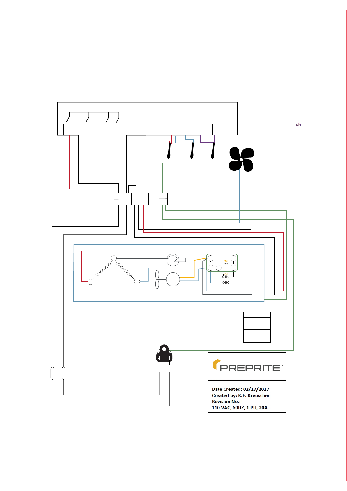
PPT481C, PPT602C, PPT843C Wiring Diagram
PPT Wiring Diagram
PPT002
16
Evap Probe
Cnd. Probe
Air Probe
Evco EVR234N9 Control
G
G
Evap Fan
Probes are as Follows;
Use shrink tubing to identify
Air Temperature Probe - Purple
Evaporator Probe - Blue
Condenser Probe - Red
G
W
WW
S
WR
K1 K4 K2 K3
B
B
BL
BI
20 A Fuses
Green
BlackWhite
R
1 2 3 4 6 75 8 9 10 11 1312
R
N
Power Supply
Relay
Start Capacitor
Run Capacitor
Compressor Winding
Overload
L
Red
BL Black
B Blue
W White
G Green
C
R
Condenser
FM
14 4
2
5
Compressor Starting Wiring Diagram
GC
CN
N
N
N
L
L
GEF
EF


15600 37th Ave N •Suite 100 •Plymouth, Minnesota 55446 •888-227-1629 •Everidge.com •info@e
© LPL 03/2020
veridge.com
Walk-In Coolers/Freezers • Restoration & Replacement Doors
Cook-Chill Specialty Solutions • Parts, Service & Warranty • Construction Services
Proud to be family-owned.
NOTES:
This manual suits for next models
35
Table of contents
Other Everidge Commercial Food Equipment manuals


Popular Commercial Food Equipment manuals by other brands


Diamond
Diamond AL1TB/H2-R2 Installation, Operating and Maintenance Instruction

Salva
Salva IVERPAN FC-18 User instructions

Allure
Allure Melanger JR6t Operator's manual

saro
saro FKT 935 operating instructions

Hussmann
Hussmann Rear Roll-in Dairy Installation & operation manual

Cornelius
Cornelius IDC PRO 255 Service manual

Moduline
Moduline HSH E Series Service manual

MINERVA OMEGA
MINERVA OMEGA DERBY 270 operating instructions

Diamond
Diamond OPTIMA 700 Installation, use and maintenance instructions

Diamond
Diamond G9/PLCA4 operating instructions

Cuppone
Cuppone BERNINI BRN 280 Installation

Arneg
Arneg Atlanta Direction for Installation and Use