FINO FINOCAM A5 Operation manual

FINOCAM A5
06260DE
Original FINO
Germany
Tischfräsmaschine
Table Milling Unit
Gebrauchsinformation•User Information•Mode d’emploi
Información sobre el uso•Informazioni d’uso
Gebruiksaanwijzing•Instrukcja stosowania
FINO
•der feine Unterschied•the fine difference•la fine différence•la fina diferencia•la fine differenza

Version 1/2016. Read the User Manual prior to commencing work!
1. About this document 3
• Used symbols • Structure of safety notes
2. Safety instructions & regulations 3
• General safety instructions • Regulations
3. Machine description 6
• Connection panel• Front cover• Working chamber • Accessories container
• Air extraction concept • Manufacturing software and computer • Sound emission
• Technical data
4. Installing the machine 11
• Checking the scope of delivery • Choosing the installation site
• Machine installation (scheme) • Installing the pneumatics
• Installing the air extraction system • Establishing the electric connection
• Removing the transport lock • Connecting the manufacturing computer
• Testing the machine
5. Running the machine 18
• Starting up the machine • Job execution overview • Inserting/changing tools
• Inserting and removing workpieces • Executing jobs • Interrupting the job execution
• Operation interruption or abortion of job execution • Emergency release of the front cover
6. Machine maintenance and cleaning 25
• Definition of wear parts • Maintenance table • Inspection
• Cleaning the working chamber and measuring key • Cleaning the collet chuck
• Checking the hoses, cables and connections • Cleaning the housing
• Checking the service unit • Exchanging the main fuse • Calibrating the axes
• Replacing the tool changer inserts
7. Disposal 32
8. Troubleshooting 32
9. Index 36
CONTENTS
2

1. About this document
1.1 Used symbols
Instructions
➤General instruction
MSpecific manual action
SSpecific action in the manufacturing software
➡Result
Additional symbols
➲Cross reference
•List
Information to make work more efficient.
Important instructions without any danger
for people or objects.
Additional information
Structure of safety notes
Type and source of hazard
Further explanations and consequences when igno-
ring hazards.
➤Instructions to avoid hazards.
The following signal words may occur in this docu-
ment:
DANGER indicates a hazardous situation which will
result in death or serious injury.
WARNING indicates a hazardous situation which can
result in death or serious injury.
CAUTION indicates a hazardous situation which, if
not avoided, can result in minor or moderate injury.
NOTICE indicates a situation which can lead to phy-
sical damage of the product or in the surrounding
area(s).
SIGNAL WORD
!
DANGER
!
WARNING
!
CAUTION
!
NOTICE
2. Safety instructions & regulations
2.1 General safety instructions
Incorrect operation of the machine
➤Read this document carefully before installing
and operating the machine.
➤If it is unclear how to operate the machine in
any way, do not use the machine and contact
customer service.
➤Make sure that every user has access to this
document.
➤Instruct every user on safe and proper machine
handling.
Danger to life due to an electric shock
If you come into contact with electrically
charged parts, you can suffer from an elec-
tric shock. Water increases the risk signifi-
cantly.
➤Do not remove the housing of the machine.
➤Only have qualified electricians work on any
electric equipment.
➤Run power cables so that they cannot be dama-
ged by sharp edges.
➤In the following cases, disconnect the
machine from the electrical source imme-
diately and prevent it from being restarted:
• When machine connections, compressed air
hoses or electric cables are damaged
•Before you check or run electric cables
➤Never perform any troubleshooting while the
machine is operating.
➤Only have authorized service technicians repair
the machine.
➤Replace damaged cables with original manu-
facturer’s spare parts.
➤Install an operational Residual Current Device/
Ground Fault Circuit Interrupter on the electric
circuit of the machine.
➤Do not touch the machine and especially the
cables with wet or damp hands.
➤Remove any liquids near the machine imme-
diately.
DANGER
!
3
ENU

Respiratory diseases when processing
harmful materials
If you inhale harmful materials during their proces-
sing, your respiratory tracts may be damaged.
➤Only process materials when an air extraction
system is running.
➤Avoid materials which can damage your health
during dry machining.
➤Use a suction device with an extra-fine particle
filter.
Crushing hazard and risk of cutting injuries
through moving machine parts
Through the moving axes and the rotating spindle
you can suffer bruises and cuts.
➤Only operate the machine when the front cover
is closed and the safety interlock is activated.
➤Store the key for the emergency release in a
place where only authorised persons have
access.
➤Do not circumvent or deactivate safety devices
of the machine.
➤Check the machine regularly for damage,
especially the safety devices.
➤Have damaged safety devices repaired by an
authorised service centre unless stated other-
wise in this document.
➤Use only original manufacturer’s equipment and
original spare parts in the machine.
➤Keep children and animals away from the
machine.
➤Do not remove the housing of the machine.
Administrator mode: risk of cutting injuries
and bruises as well as hazards through
ejected debris
If you operate the machine in “Administrator mode”
with the front cover open, the risk of injury is increa-
sed significantly!
➤Operate the machine in “User“ mode only unless
you have been authorised by FINO GmbH to use
other profiles.
➤Even if you are an authorised user, use the
“Administrator mode” with the front cover open
only when necessary.
WARNING
!
➤While in “Administrator mode”: Do not
reach into the working chamber while
the axes are moving or during machining.
➤While in “Administrator mode”:
Everyone within reach of the machine
must wear protective eye wear.
Hearing damage due to loud noise
➤In case of extraneous machining noise check the
working conditions: Ensure that the workpiece is
fixed properly, and verify the condition of the
tool and the material you are using.
➤If loud noise cannot be avoided, wear
ear protection during processing.
Risk of injuries through loose pneumatic com-
ponents under air pressure when connections
are open
Loose pneumatic components can move extremely
fast and unpredictably and may cause injury.
➤Before you run the pneumatic hoses, close the
compressed air supply valve.
➤Before you check the pneumatic hoses and
pneumatic connections, set the air pressure to a
minimum value.
➤In case of defective machine connections
and pneumatic hoses, disconnect the
machine from the external compressed air
supply and the electrical source to prevent
it from being restarted.
➤Contact customer service if connections are
damaged or defective.
4

Trip, fall and slipping hazards
➤Keep the working environment and
installation site clean.
➤Run cables in such a way that persons
cannot trip over them.
Risk of cutting injuries and burns
If you touch tools or sharp edges on workpieces or
the machine, you may suffer from cuts. If you touch
the hot spindle body or hot tools, you may suffer
from burns.
➤Wear gloves when you perform manual work at
the machine or with workpieces/tools.
Reduced ability to act with insufficient lighting
In case of an insufficient lighting your judgement
and/or your precision may be reduced.
➤Make sure that the lighting in your working
environment is sufficient.
Risk of injury in case of malfunctions caused
by insufficient maintenance
If you do not maintain the machine as often as is
required, malfunctions may occur which can lead to
injuries.
➤Take note of the intervals and conditions mentio-
ned in the maintenance table in this document
and carry out the respective maintenance steps
accordingly.
Health risks through constant malpositioning
if your working environment is not sufficiently
ergonomic
Over the long run, an improper or one-sided positio-
ning can be a risk to your health.
➤Set up an ergonomic work environment.
➤Ensure the seat height and monitor position is
ideal and the lighting is sufficient.
CAUTION
!
2.2 Regulations
If you violate the following regulations, you may lose
your entitlement for benefits. In addition, we cannot
be held liable for any damage resulting from such
violations.
2.2.1 Intended use
The FINOCAM A5 has been designed for easy to
medium machining work in the dental sector.
➤Only process materials that you can select in
FINOCAM. Only use the machine commercially.
➤Before creating jobs, verify if the objects being
prepared may be utilized at the place of use
according to local and/or national regulations or
other authorized organisations or entities (e. g.
professional associations, health authorities). In
particular, verify if the material is approved for
the machined object type and if the object type
is designed in accordance with applicable regu-
lations. Neither the manufacturing software nor
the CNC machine will inform you about possible
regulatory infringements, but will executes jobs
in accordance with the preferences and materi-
als set by the user.
➤Verify that each object type and each material in
your jobs are authorized to manufacturing mate-
rials. If mandated by local or national regula-
tions, obtain relevant authorization from the
responsible organisation or entities (e. g. pro-
fessional associations, health authorities).
➤Only manufacture objects which correspond to
the object types that you can select in the import
view in FINOCAM. While you can import/manu-
facture any other objects as well, neither the
manufacturing software nor the CNC machine
are designed for these other objects and should
not be used in this way.
➤Do not manufacture implants or parts of objects
that are designed to have contact with implants.
These parts include parts of two-part abutments
which contain the connection geometry for the
implant. Do not manipulate the connection geo-
metry of prefabricated abutments (“prefab abut-
ments”) and you must always check finished
objects for accurate connection geometries (i.e.
that connection geometries of finished jobs have
not been damaged).
5
ENU

2.2.2 Controlling the machine through
software
You control the CNC machine through specially
designed applications which are supplied with the
machine.
➤Only use program versions that are officially
released for the machine.
➤Always use the newest program versions that
are available for the machine.
➤Before installing or operating the machine, be
sure to read the documentation for the applica-
tions.
2.2.3 Maintenance and cleaning
➤Clean and maintain the CNC machine as
required. Only then can the machine reach a
long service life.
➤Only carry out maintenance work which is de-
scribed in this document. Otherwise you risk
your health and may damage the machine.
2.2.4 Synchronous spindle SFK 300P
➤Do not use unbalanced tools at high rotational
speeds. Such an imbalance puts a great strain
on the spindle’s ball bearings, which can cause
the bearings to be dam- aged.
➤When working in the working chamber, do not
apply manual pressure against the spindle.
2.2.5 Unattended operation
➤Unattended operation of the CNC machine
should only occur if the following conditions are
met:
• The national and local laws allow it.
• The working chamber of the machine is comple-
tely clean.
• Unauthorized users cannot access the machine.
• The room in which the machine is located has an
automatic fire detection system.
2.2.6 Transport ation and storage
Damaging of the machine if you transport the
machine without the transport lock
If you transport the machine without installing the
transport lock first, the machine may get damaged.
➤Before every transport, install the transport lock
as it was installed at delivery
• Ambient temperature: between 10 °C and 35 °C
• Relative air moisture: max. 80 %, non-conden-
sing
• For (un)packing and positioning two people are
required
• Weight of the machine: approx. 91 kg
➤Always transport multiple machines
individually and do not stack them.
➤Only trained transport personnel may transport
the machine to the installation site.
➤Always transport the machine in an upright posi-
tion.
➤Transport and position the machine only with a
closed accessories container.
➤In case of overseas transport, take proper
measures against corrosion.
➤To carry the machine, use the left and right grips
located on the bottom of the machine.
3. Machine description
Fig. 1: Front view of the FINOCAM A5
NOTICE
6

1Connection panel (➲Fig. 2)
2Front cover
3View window to the working chamber
4Recessed grip for opening
5Accessories container
6Opening for the air extraction system
With your FINOCAM A5 you can process workpieces
of different materials to create high quality objects
for the dental sector.
You can find a list of the materials which you can
process with the FINOCAM A5 in the FINOCAM
manufacturing software.
3.1 Connection panel
Fig. 2: The connection panel
1Power connection 100 – 240 V AC, 50/60 Hz,
including glass fuse T6,3A L250V
2Main power switch
3Pneumatic connection
4USB connection
5Switching output for suction device
3.2 Front cover
The front cover locks the working chamber and
protects the user from injuries during operation.
Crushing hazard when opening or closing the
front cover
When you open or close the front cover, the moving
front cover may crush your fingers.
➤When you open and close the front cover, use
one hand and keep the other hand away from the
machine.
➤When you close the front cover, ensure your
hands do not get caught between the front cover
and the machine housing.
CAUTION
!
Damaging of the machine when opening the
front cover by force
When the CNC machine is not supplied with power or
when the axes are moving, the front cover remains
locked. If you open the locked front cover by force,
the machine may get damaged.
➤Never open the front cover by force.
➤Connect the machine to the electrical source
and switch it on first before opening the front
cover.
➤To open the front cover, grasp the recessed grip
and pull the front cover upwards.
Fig. 3: The FINOCAM A5 with the front cover open
➤To close the front cover, put your hand flat on
the upper edge of the front cover and push the
front cover downwards.
3.3 Working chamber
The machine processes all workpieces in the working
chamber.
Fig. 4: The working chamber of the FINOCAM A5
NOTICE
7
ENU

1Rotational axis B
2Workpiece holder and rotational axis A
3Fixing disc
4Collet chuck for picking up tools
5Spindle
6Tool changer for up to 16 tools
Colours of the working chamber lighting
If the working chamber lighting is insufficient,
provide additional lighting.
Your FINOCAM A5 illuminates the working chamber
in different colours. The colour will change depen-
ding on the state of the machine. You will find the
colours and respective machine statuses in the follo-
wing table:
3.4 Accessories container
In the accessories container below the working
chamber, you can store workpieces, tools, and the
spindle service set ready to hand.
➤To access the accessories container, simply pull
it out of machine.
Fig. 5: Opening the accessories container
Colour Status
Green Machine is ready, front cover closed
White Machine is ready, front cover closed
Blue Machine is executing a job
Red A machine malfunction has occurred
8
Fig. 6: The open accessories container
(blanks and tools not provided)
➤To close the accessories container, push it into
the machine until it is completely closed.
3.5 Air extraction concept
The air extraction concept consists of:
• Air that is emitted from the spindle and the
bellow
• The external air extraction system (suction
device, suction hose, optional switching unit)
• The vacuum sensor
During job execution, the machine constantly blows
air into the working chamber (➲ Fig. 7, upper arrows).
An external suction device that you connect to the
CNC machine with a suction hose extracts the
machining debris from the working chamber (➲ Fig.
7, lower arrow).
This concept decreases the soiling and wear of
sensitive machine parts.
The air extraction system does not replace the
regular cleaning of the machine. Without regular
cleaning, the machine life decreases signifi-
cantly.
Through the air extraction, a vacuum develops in the
working chamber which is constantly monitored by a
vacuum sensor (display in FINOCNC: ➲ chapter
4.9). If the vacuum is too weak, machining is not
possible. If the vacuum becomes too weak during a
running job, FINOCNC interrupts machining until the
vacuum is sufficient again (➲ chapter 5.7).
The current strength of the vacuum displays in
FINOCNC (➲chapter 4.9 or in documentation for the
manufacturing software).

Sound measurement
Measuring conditions:
• Processed material: CoCr
• Tool status: new
• Distance to sound source: 1 m
• Measurement according to ISO 3746,
engineering method 3
3.8 Technical data
Base system
• Dimensions (W/D/H):
approx. 450 x 530 x 630 mm
• Weight: approx. 91 kg
• Air pressure (min./max.): 6 bar/8 bar
• Recommended air pressure: 7 bar
• Air consumption: ca. 40 l/min at 6 bar,
approx. 50 l/min at 8 bar
• 5-axis mechanism;
positioning range (x/y/z): 165.5 x 108 x 93 mm
• Complete housing of the working chamber;
front cover with a safety contact and safety
interlock
• Vacuum sensor for monitoring the extraction
capacity
• Minimum extraction capacity: 2500 l/min
• Accessories container in drawer shape
• Working chamber lighting with different colours
to indicate the machine state
Rotary axes
• Rotation range: 360 ° (A) | ±35 ° (B)
• Exchangeable workpiece holder
Spindle
• Synchronous spindle rotating up to 60,000 RPM
• Nominal power under continuous load (S1):
300 Watts
• Maximal Power (Pmax): 500 Watts
• 4-fold bearing
• Hybrid ceramic ball bearing
• Pneumatic collet chuck ø 3 mm
• Cone cleaning and sealing air
Operating condition Maximum A-weighted
sound pressure level
Processing 71 dB(A)
All other operating
conditions (tool change,
movement of the axes
etc.)
<70 dB(A)
9
ENU
Fig. 7: Air extraction concept in the working chamber
3.6 Manufacturing software and
computer
To operate the machine, you must use a computer
running Windows®(“manufacturing computer“)
which should connect to the machine via the provi-
ded USB cable.
You can process manufacturing jobs with the manu-
facturing computer in 2 steps:
1. With FINOCAM you can create jobs with the
objects that you want to machine. FINOCAM
already contains all important parameters for the
different materials.
2. You can execute the jobs with the CNC software
FINOCNC. This application offers additional
maintenance and control functions for the
machine.
You must use a different computer together with
a scanner and suitable software to create 3D
models of the objects (not provided, sold by
specialist dealers).
3.7 Sound emission
The actual sound emission of the machine varies
heavily depending on the manufacturing material
and the machining conditions.
➤If the machine is too loud, check the operating
conditions. Ensure that the workpiece is fixed
properly, check the condition of the tool and the
material in use.
➤If loud noise cannot be avoided, wear ear pro-
tection during machining.

10
Tool changer
• Automatic tool changer for 16 tools
• Maximum tool length: 40 mm
• Automatic tool length measurement and tool breakage monitoring via measuring key
• Compressed air monitoring for the automatic tool change
For additional information on tools see ➲ chapter 5.4.

11
4. Installing the machine
4.1 Checking the scope of delivery
M Unpack the machine and ensure you have recei-
ved the following items:
ENU
11 CNC machine FINOCAM A5
21 spindle service set in the accessories container
31 power supply cord
41 USB cable
51 service unit for compressed air
61 torque wrench 1.5 Nm in the accessories container
71 drill bit (2.8 mm) for tool positions
81 calibration set: 1 micrometre, 3 blanks,
1 calibration tool
91 measuring pin
10 1 key for the emergency release of the front cover
11 1 Advanced Tool Board (ATB) in the accessories
container
12 1 pneumatic hose
13 2 tool changer inserts (as spare parts)
14 1 USB dongle
Without illustrations:
• This document
• Documentation for FINOCAM & FINOCNC
• 1 socket wrench in the accessories container
for replacing the measuring key (to be used
by the service technician)
• 4 screws for the workpiece fixation as spare
parts
➤Please keep the machine packaging for future
transport.
4.2 Choosing the installation site
➤The installation site must meet the following
criteria:
• Firm and even surface, must carry the weight
of the machine
• Room temperature ideally between 18° Celsius
and 25° Celsius, maximum room temperature
32° Celsius
• Machine location must be dust-free
• Relative air moisture maximum 80 %,
non-condensing
• Alternating current source with 100-240 V
and 50/60 Hz
• Compressed air supply that meets the require-
ments of the machine (➲ chapter 4.4)
• Sufficient space at the sides of the machine
(➲ page 10)
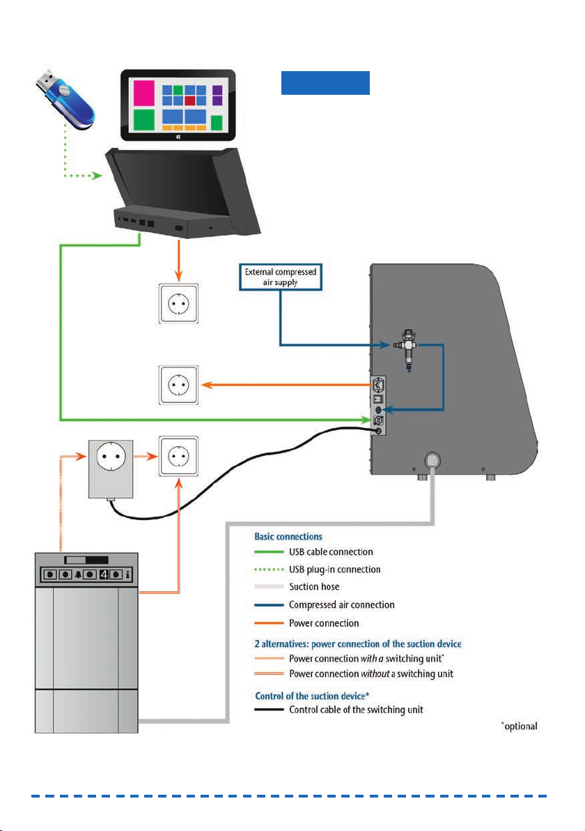
4.3 Machine installation (scheme)
12
Damage to the machine due to incorrect
installation
➤Carry out the installation in the given order.
➤Ensure to remove the transport lock before instal-
ling the manufacturing computer (➲chapter 4.7).
NOTICE

13
ENU
4.4 Installing the pneumatics
Risk of injuries through leaking compressed
air and lashing pneumatic hoses
Open or loose pneumatic connections can cause
severe injuries.
➤Make sure that during installation and service
of the pneumatic hoses and of the service unit
compressed air is not running through the hoses
and connections.
➤After installing the pneumatic hoses but before
running compressed air through the hoses and
connectors, check if the hoses are securely
inserted into the correct connectors and are not
damaged.
➤Do not run compressed air through damaged
hoses and connectors.
The spindle may suffer bearing damage and
electrical damage if the compressed air is
contaminated
The incoming compressed air must be dry and oil-
free according to ISO 8573-1 because the service
unit only serves as an indicator for contaminated
air.
Air purity according to ISO 8573-1
Solid particles, Class 3,
Filtration degree better than 5 µm for solid particles
Water content, Class 4,
Maximum pressure dew point +3 °C
Residual oil content, Class 3,
Maximum oil content: 1 mg/m3
➤Ensure that the compressed air meets the above
requirements.
➤Connect the machine to the compressed air
supply only via the provided service unit.
The spindle requires compressed air for the
following tasks:
• For the opening and closing of the collet chuck
during tool change.
• For the sealing air which prevents foreign bodies
from entering the spindle.
Air consumption of the machine:
• approx. 40 l/min at 6 bar
• approx. 50 l/min at 8 bar
WARNING
!
NOTICE
4.4.1 Overview service unit
Via the service unit you connect the CNC machine to
your compressed air supply and regulate the inco-
ming pressure for the machine.
Fig. 8: The service unit:
Regulation and checking the air pressure
1Rotary knob for pressure regulation
2Pneumatic connection to the machine (ø 6 mm)
3Manometer for monitoring the outgoing pressure
4Water separator
5Discharging screw
6Pneumatic connection for external
compressed air supply
4.4.2 Mounting the service unit
on the CNC machine
Failure of the water separator caused by a
wrong alignment of the service unit
The service unit must always be mounted in an
upright position because otherwise the water
separator will not work.
➤Mount the service unit in an upright position
(➲ Fig. 8). On the left side of the CNC machine
are two drilled holes which you can use to mount
the service unit on the machine.
NOTICE
14
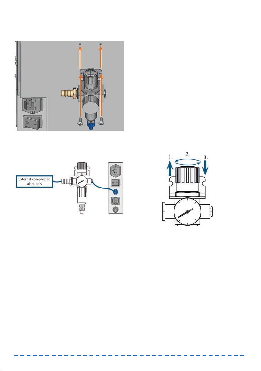
M1. Remove the two blind screws in the drilled holes.
M2. Mount the service units with the provided lens
head screws in an upright position.
Fig. 9: Mounting the service unit on the machine
4.4.3 Installing the pneumatic hoses
to the service unit
Fig. 10: Installation of the service unit (scheme)
M1. Close the external compressed air supply valve.
M2. Use the provided pneumatic hose to connect the
right pneumatic connection of the service unit
[Fig. 8, 2] with the pneumatic connection of the
machine.
M3. Connect the external compressed air supply with
the left pneumatic connection of the service unit
[Fig. 8, 6].
M4. Check the installation carefully for errors and
damage. Do not run compressed air through
damaged or loose hoses and connections!
M5. Open the external compressed air supply.
M6. Check the air pressure on the manometer
[Fig. 8, 3]. If it does not lie between 6 bar and
8 bar, adjust it with the service unit (➲chapter
4.4.4)
4.4.4 Adjusting the air pressure with
the service unit
Setting the air pressure is only necessary if the air
pressure shown by the manometer does not lie
between 6 bar and 8 bar.
M1. Check if the service unit is correctly connected
to the machine and the compressed air supply
(➲chapter 4.4.2 onwards).
M2. Pull the rotary knob on top of the service unit
slightly upwards.
M3. Turn the rotary knob in the desired direction until
the pressure lies between 6 bar and 8 bar
(recommended: 7 bar):
• Turning it towards “+“ you increase the
pressure
• Turning it towards “–“ you decrease it
M4. Push the rotary knob down again.
➡The knob is locked and cannot be changed
inadvertently.
Fig. 11: Setting the air pressure
4.5 Installing the air extraction system
How the air extraction system works:
➲chapter 3.5
Available components of the air extraction system:
• Suction device including suction hose
•Switching unit for switching the suction device
on and off via the CNC machine
• Hose connection for suction hose: if the suction
hose does not fit into the machine
Which components are required and how you can
combine them is listed in the following table.

You obtain the switching unit via customer service if
necessary.
4.5.1 Requirements for the suction
device
➤Use a suction device with the following
properties
only:
• Designed for the commercial use in the
dental sector
• Equipped with a filter of the filter class M
• Suitable for the operating site of the CNC
machine
• Equipped with safety devices which protect
you from static discharges (e. g. through an
anti-static suction hose)
• Minimum extraction capacity: 2500 l/min
4.5.2 Absauggerät anschließen
➤Before the installation of the suction device read
the documentation for the device and have the
documentation always ready at hand.
M1. Check if the connection of the suction hose has
an outer diameter of 45 mm. If the diameter is
different, use the optional hose connection
(➲chapter 4.5.3.)
M2. Insert the suction hose of the suction device into
the opening for the air extraction of the CNC
machine. Make sure that the suction hose is
firmly connected.
Fig. 12: Inserting the suction hose into the machine
Component Source Required? Prerequisite
Suction device Customer service,
specialist dealers
Yes –
Switching device Customer
service
Nein –
Hose connection Customer
service
If the suction
hose does
not fit
Ask customer
service
M3. If you want the machine to automatically switch
the suction device on and off, install the
switching unit (➲chapter 4.5.4. If you require a
switching unit, contact customer service.
M4. Continue with the installation of the suction devi-
ce as described in the documentation for the
device.
4.5.3 Connecting the suction hose with
the optional hose connection
If you can connect the suction hose of your
suction device directly to the CNC machine, you
do not need the hose connection.
M1. Obtain the hose connection via customer ser-
vice.
M2. Turn the thread of the hose connection counter-
clockwise until the connection is completely
open. If the thread gets detached from the hose
connection, place it onto the connection again
and turn it clockwise once so that it is screwed
to the connection again.
M3. Insert the suction hose of the suction device
completely into the hose connection on the side
of the thread.
Abb. 13: Inserting the suction hose
into the hose connection
M4. Turn the thread of the hose connector clockwise
up to the stop.
➡The suction hose is firmly attached to the hose
connection.
M5. Insert the hose connection into the opening for
the air extraction system of the machine. Ensure
it is firmly connected.
15
ENU

Fig. 14: Inserting the hose connection into
the opening for the air extraction system
➡The installation of the suction hose with the
optional hose connection is complete.
4.5.4 Installing the switching unit
M1. Connect the power cable of the suction device to
the switching unit.
M2. Connect the control cable of the switching unit
to the switching output at the connection panel
of the CNC machine.
M3. Plug the switching unit into a power socket.
Fig. 15: Connecting the switching unit to
the suction device and the machine
4.6 Establishing the electric connection
Damaging of the machine through heavy
voltage fluctuations
Heavy voltage fluctuations can disrupt the control
unit and can cause system failure.
➤Plug the machine’s power cord in a dedicated
circuit current or ensure that no devices are
connected that can cause heavy voltage fluctua-
tion when switched on.
NOTICE
Damaging of the machine if the transport lock
and the manufacturing computer are installed
When you connect the machine to the electrical
source and the manufacturing computer is con-
nected, the machine starts referencing. During this
process, the transport lock which is installed at deli-
very can damage the mechanics of the machine.
➤Do not connect the machine to the electrical
source if the manufacturing computer and the
transport lock are installed.
➤If the transport lock is installed, disconnect the
USB connector between the machine and the
manufacturing computer before connecting the
machine to the electrical source.
M1. Plug the provided power cord into the power
connection at the connection panel of the CNC
machine.
M2. Put the plug of the cord into a socket that is pro-
tected by a Residual Current Device/Ground
Fault Circuit Interrupter.
4.7 Removing the transport lock
Before operating the machine for the first time, you
must remove the transport lock. The transport lock
prevents the spindle from getting damaged during
transport.
M1. Disconnect the USB connector between the ma-
chine and the manufacturing computer.
M2. Connect the machine to the electrical source.
M3. Switch on the machine via the main power
switch.
Fig. 16: Turning on the main power switch
M4. Open the front cover.
NOTICE
16

Fig. 17: Removing the transport lock
1Upper part of the transport lock
2Bottom part of the transport lock
M5. Carefully pull the bottom part of the transport
lock (2) towards you and out of the working
chamber.
M6. Carefully lift the upper part of the transport lock
(1) out of the workpiece holder. Pull it towards
you and out of the working chamber.
M7. Clean the working chamber from parts of the
transport lock that may have broken off.
M8. Store the transport lock safely to use it for future
transports.
4.8 Connecting the manufacturing
computer
The transport lock must not be installed when
you connect the manufacturing computer to the
machine (➲ chapter 4.7).
M1. Switch on the machine.
M2. Close the front cover.
M3. Start the manufacturing computer.
M4. Use the provided USB cable to connect a USB
port of your computer or docking station with
the connection panel of your CNC machine.
M5. Insert the dongle into a USB port of the manu-
facturing computer or docking station.
S6. Install the newest version of FINOCAM and
FINOCNC that is released for the machine. For
more information on this, read the documenta-
tion for the applications.
S7. Start FINOCNC and click on the de-
picted icon in the icon bar.
S8. Click on the depicted icon in the lower
icon bar.
➡The application settings view displays.
S9. Click on the depicted icon beside the
text Port number.
➡FINOCNC will try to establish a connection to the
CNC machine. If this is successful, the applica-
tion will display the port number beside the icon
and the machine references.
The machine will not reference if the front cover
is open.
M10.If the front cover was open at step S9, close it. If
the machine does not reference as a result, quit
FINOCNC and restart the application.
M11.If FINOCNC did not determine the port number,
read how to determine the port number manually
in the documentation for the application.
4.9 Testing the machine
After the first installation or after a re-installation, for
example after a transport, you should test the basic
functions of the machine.
M1. Switch on the machine.
M2. Close the front cover.
➡The machine starts up. The working chamber is
illuminated in white.
M3. Open the compressed air supply valve.
S4. Start the manufacturing computer and start
FINOCNC.
➡The machine will reference and the working
chamber will illuminate in green. The machine is
now in
default position
.
S5. In the upper icon bar, click on the
depicted icon.
M6. Switch on the suction device and select the
necessary extraction level.
S7. If the machine controls the suction
device via a switching unit, click on the
depicted icon.
➡The suction device is operating and a vacuum
develops in the working chamber.
M8. With the value bars and icons depicted below,
verify that the compressed air and the vacuum in
the working chamber are sufficient.
17
ENU

18
➡The icons display in blue when the compressed
air and the vacuum are sufficient.
Fig. 18: Top: Value bar and icon for compressed air
Bottom: Value bar and icon for the vacuum
S9. Move the spindle to the cleaning posi-
tion by clicking on the depicted icon.
➡The spindle should move through the working
chamber at constant speed.
S10. Move the spindle from the cleaning
position back to the default position by
clicking on the depicted icon.
➡The spindle moves to the default position at
constant speed.
S11. If the machine controls the suction devi-
ce, click on the depicted icon.
M12.If you control the suction device manually,
switch it off. The suction device stops operating.
M13.Open and close the front cover.
➡The front cover can be opened and closed
easily.
M14.If a result did not occur as described, check the
following depending on the error:
• The USB connection & USB driver installation
(➲ chapter 4.8 & documentation for the manu-
facturing software)
• The compressed air supply (➲ chapter 4.4)
• The set extraction capacity of the suction device
• The installation of the air extraction system
(➲chapter 4.5)
M15.If you cannot solve a problem that occurred,
contact customer service.
5. Running the machine
5.1 Starting up the machine
M1. Close the front cover.
M2. Switch on the machine and the manufacturing
computer.
➡The machine and manufacturing computer start
up. When the machine has started up, the wor-
king chamber is illuminated in white.
M3. If machine controls the suction device, switch on
the device and select the necessary extraction
level.
➡The suction device is not running.
If you control your suction device manually, you
switch on the device immediately before job
execution.
S4. Start FINOCNC.
➡The machine references. Afterwards the working
chamber is illuminated in green. The machine is
now ready for use.
The machine will not reference if the front cover
is open.
M5. If the working chamber is illuminated in red,
switch the machine off and on again. If the wor-
king chamber is still illuminated in red, contact
customer service.
M6. If the front cover was open at step S4, close it.
S7. If the machine does not reference as a result,
quit FINOCNC and restart the application.
5.2 Job execution overview
Damaging of the machine when using
damaged tools or workpieces
If tools or workpieces are damaged, parts can break
off and damage the machine during job execution.
➤Check the workpieces and tools thoroughly for
damage before every job execution.
Carrying out a typical job with the FINOCAM A5 is as
follows:
1. Create a job in FINOCAM
2. Insert the tools into the machine
3. Insert the workpieces into the machine
4. Execute the job in FINOCNC
The steps in the manufacturing software are descri-
bed in the corresponding documentation. The follo-
wing text describes how to perform manual work with
the CNC machine.
NOTICE

19
ENU
5.3 Inserting/changing tools
Damaging of the spindle or the tool positions
if you use improper tools
Improper tools can damage the collet chuck of the
spindle and/or the tool positions.
➤Only use tools with a sufficiently large chamfer
at the tool shank.
➤Install a retaining ring as a stop ring according to
DIN 471-A3.
➤Only insert tools with a maximum diameter of
3 mm at the thickest part into the collet chuck.
➤Only insert tools with a maximum cutting edge
diameter of 2.6 mm into the tool changer.
We recommend original tools as they are desig-
ned especially for the designated jobs.
You can insert up to 16 tools into the tool changer.
The machine can change tools automatically during
machining so that it executes jobs without your inter-
ference.
Fig. 19: Tool changer positions in the working chamber of
the machine (marked orange)
You can equip the tool changer in two ways:
• Via the spindle – you insert a tool into the collet
chuck and the spindle will deposit the tool in the
tool changer. This function is described in the
documentation for the manufacturing software.
• By inserting the tools into the tool changer
manually. This is described below.
You insert the tools manually as follows:
S1. Start FINOCNC.
S2. Call up the job execution view and select the job
that you want to execute from the job list.
➡FINOCNC displays the tools that are assigned to
the job in the lower part of the application win-
dow.
M3. Open the front cover.
NOTICE
M4. Insert the tools into the tool positions of the tool
changer:
• Insert the tools straight into the tool positions
and push them in until the ring touches the
rubber (➲ Fig. 20).
• The positions of the tools in the tool changer
must match the tool positions in FINOCNC
(➲ Fig. 21).
If the positions of the tools in the tool changer
do not match the tool positions in FINOCNC, the
machine will use the wrong tool(s) during job
execution and the job result will become unusa-
ble.
Fig. 20: Inserting tools straight into the tool position

Fig. 21: Top: tool positions 1 – 16 in the tool changer
Bottom: tool positions 1 – 16 in FINOCNC
5.4 Inserting and removing workpieces
On delivery, your FINOCAM A5 processes blanks
with a diameter of 98.5 mm.
5.4.1 Inserting blanks
You put blanks into the workpiece holder and immo-
bilize them with a fixing disc.
Fig. 22: The fixing disc (blue) is attached to the workpiece
holder (grey) with 4 screws (orange)
M1. Open the front cover.
M2. Unscrew the 4 screws which attach the fixing
disc to the workpiece holder.
M3. Remove the fixing disc and the blank in the
workpiece holder (if any).
M4. Place the blank into the workpiece holder.
Fig. 23: Placing the blank into the workpiece holder
M5. Place the fixing disc onto the workpiece holder
on top of the blank.
20
Table of contents
Other FINO Power Tools manuals


