Landoll ICON 819 Building instructions

F-882-0118
LANDOLL COMPANY, LLC
1900 North Street
Marysville, Kansas 66508
(785) 562-5381
800-428-5655 ~ WWW.LANDOLL.COM
Model 819 Scraper
Service and Parts
Manual


Foreword
Literature Information
This information should be stored in the
literature holder located on the machine.
This manual contains safety information,
operating instructions, lubrication and
maintenance information.
Some of the photographs or illustrations in the
publication show details that can differ slightly
from your personal machine. Shields and covers
may have been removed to allow for
illustrations.
Constant improvement and knowledge of
product design may cause changes to your
personal machine that is not listed in this manual.
Read, understand, and keep this manual with the
machine to aid in repairs, adjustment, service and
parts identification.
Whenever a question arises regarding your
machine, or this manual, please contact Product
Support for assistance.
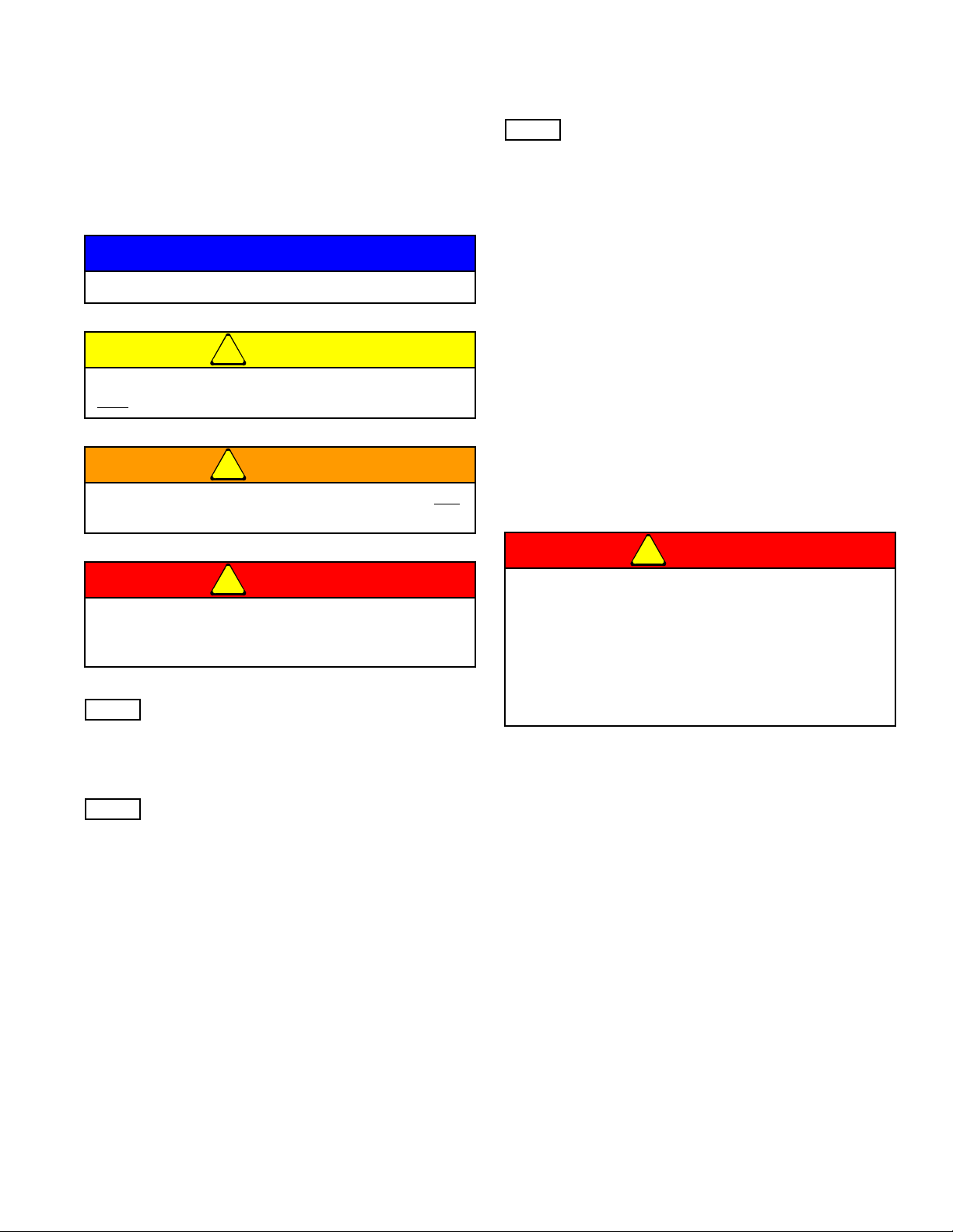
Safety
The safety section of this manual lists basic
safety precautions. In addition, this section
shows the location of safety signs and decals
used on this machine.
Read and understand the basic precautions
listed in the safety section before operating or
performing lubrication, maintenance or repair
work on this machine.
NOTE: Before any service or repair work is
performed, make certain that all safety stops
are in place.
Be certain to remove all safety stops when
repairs are complete.
Operation
This operation section is a reference guide for
the new operator and a refresher for the
experienced operator. Operating techniques
shown are basic, skill and technique will increase
with knowledge and usage of the machine.
Maintenance
The maintenance section is a guide to
machine care. The illustrated step by step
procedures covers the most important of the
maintenance schedule. Regular routine
lubrication is described in less detail.
Maintenance Intervals
Normally, all lubrication should be on a
daily basis. However, certain locations only
require lubrication on a weekly basis or
require a specific quantity. These locations
will be marked clearly, showing and
describing requirements.
Under extremely severe, dusty/wet/sandy
conditions, or if the haul is long and rough,
more frequent lubrication and inspection of
highly stressed areas is recommended.

A. Safety Information & Product Warranty
B. Standard Specifications
C. Axle Adjustment
D. Damage While Pushing
E. Mounting/Dismounting Of Earthmover
F. 800 Parts Listing
G. 800 Components
H. Bolt Listing
I. Component Photos
J. Swivel Hitch
K. Hub/Axle Assy.
L. Brake Components
M. Cutting Edges & Components
N. Accumulator
O. Hydraulic Components
P. Decal & Safety Sticker Location
Q. Axle Seal Replacement
Table Of Contents

Safety Information
Introduction
This manual is compiled as a guide for owners and
operators of the Scraper. Read it carefully so as to be
able to follow the suggestions made. Please take time to
understand the proper maintenance schedule and SAFE
operation of your equipment.
In the event that a new and inexperienced operator is
placed in charge of running the equipment, they should
read and understand, that part of the manual for proper
maintenance and SAFE operation, and to be trained in
regard by an experienced operator.
Owner Assistance
If customer service or repairs are needed, contact your
Icon dealer. They have trained personnel, parts and
service equipment specially designed for Icon products.
Your machine’s parts should only be replaced with Icon
parts. Have the Serial Number and complete Model
Number available when ordering parts from your Icon
dealer (See Figure 2-1.)
Figure 2-1: ID Plate
Warranty Registration
Be certain to register the grader, by Online registration at
www.landoll.com within 10 days of purchase or lease, in
order to be on file at Landoll and eligible for Warranty.
Take time to read and understand the Warranty for this
product. That Warranty is printed in the Owner’s Manual
(See Figure 2-2), and a separate copy enclosed in the
packet.
ICON/Landoll reserves the right to make changes and/or
add improvements to it’s products at any time without
obligation to previously manufactured equipment.
Please take time to complete the following information for
your personal reference, should you need to contact your
Dealer with questions or parts needs.
MODEL_____________________________________
SERIAL #____________________________________
DATE OF PURCHASE__________________________
DEALER NAME________________________________
We at ICON/Landoll wish to thank you for purchasing our
product. We have spent considerable time and effort to
research, design, test and develop this machine and are
confident it will serve you in the use for which it was
designed.
MODEL #
SERIAL #
MADE IN USA 1-573-010006
Landoll Company, LLC
Marysville, Kansas
www.landoll.com

Figure 2-2: Product Warranty
LANDOLL KDWEz>>
Product Warranty
th
LANDOLL KDWEz>> 1600 W. 8 St. Beloit KS 67420
(referred to as LANDOLL in this document)
LANDOLL shall Warrant workmanship and materials on the ICON
Industrial Products for a period of 270 calendar day from the date of original
purchase, lease, or rental, from the original Dealer, and in accordance with
the following terms and conditions.
Should any part or component fail within the Warranty period, and under
normal use conditions, LANDOLL shall supply a new part or component for
replacement through the original Dealer. Cost of normal ground freight, for
that part or component to the Dealer, shall be paid by LANDOLL. Repair and
replacement labor cost, from the original Dealer, shall be paid by LANDOLL at
a rate negotiated by LANDOLL.
No further expense shall be paid by LANDOLL, including but not limited to,
loss of time or income.
LANDOLL shall not provide Warranty on any part or component that has
failed due to abuse, misuse, alteration, improper maintenance, or normal
wear. Failure occurring while being pulled by a tractor in excess of engine
horsepower, as described in the owners manual and/or posted on the
machine, is considered abuse and misuse and shall not receive Warranty.
Warranty applies only to normal. intermittent agricultural use, and not
commercial or industrial use.
In regard to some components manufactured by other companies and sold
by LANDOLL, including but not limited to tires, said Warranty shall be
provided solely by that manufacturing company.
This Warranty applies to products sold in the United States and Canada,
and is made expressly in place of all other warranties, expressed or implied.

Understanding Safety
Statements
You will find various types of safety information on the
following pages and on the machine decals (signs)
attached to the implement. This section explains their
meaning.
NOTICE
CAUTION
WARNING
DANGER
NOTE
Means that failure to follow these instructions could
cause damage to the equipment or cause it to operate
improperly.
NOTE
Make sure you read and understand the information
contained in this manual and on the machine signs
(decals) before you attempt to operate or maintain this
vehicle.
The safety statements contained in this manual relate to
the operation of the Grader.
NOTE
You should read and understand the information
contained in this manual and on the machine decals
before you attempt to operate or maintain this equipment.
• Examine safety decals and be sure you have the
correct safety decals for the machine. Order
replacement decals through your Icon dealer.
• Keep these signs clean so they can be observed
readily. It is important to keep these decals cleaned
more frequently than the machine. Wash with soap
and water or a cleaning solution as required.
• Replace decals that become damaged or lost. Also, be
sure that any new machine components installed
during repair include decals which are assigned to
them by the manufacturer.
• When applying decals to the machine, be sure to
clean the surface to remove any dirt or residue. Where
possible, sign placement should protect the sign from
abrasion, damage, or obstruction from mud, dirt, oil
etc.
DANGER
Special notice - read and thoroughly understand.
Proceed with caution. Failure to heed caution
may cause injury to person or damage product.
Proceed with caution. Failure to heed warning will
cause injury to person or damage product.
Proceed with extreme caution. Failure to heed
notice will cause injury or death to person and/or
damage product.
• Keep Riders Off of Machinery
• Do not allow anyone to ride on tractor or
machine. Riders could be struck by foreign
objects or thrown from the machine.
• Never allow children to operate equipment.
• Keep bystanders away from machine during
operation.

Safety Decals
See Decal Listing for decal locations.
NOTE
Replace all missing or damaged safety signs/decals.
Pinching or Crushing Danger
1. Moving parts that are operated by hydraulic pressure
can cause serious injury or death.
2. Use extreme caution when working around any
moving part.
3. Do not allow any person to be on or near the
machine while it is in motion.
Moving Parts
1. Be aware of all moving parts of the machine.
2. Do not allow anyone to be near, or on the machine
while operating any moving part.
Danger
1. Read and understand the operator’s manual before
using the machine.
2. Allow no person to operate the machine before
reading the manual and being instructed on proper
operation.
Caution
1. This machine is designed for off road use only.
Danger, High Pressure
1. High pressure fluid can cause serious damage to
hands and eyes.
2. Carefully relieve pressure before attempting any
3. adjustments.
4. Tighten all fittings before applying pressure.
NOTE
If fluid is sprayed into eyes or injected into skin, see a
doctor immediately!
Lubrication
1. Lubrication information is placed near each zerk.
2. Proper maintenance should be followed to assure the
working life of the machine.
Proper Notification
1. Contact the proper authorities before you dig.
2. When digging in a populated area, it is
recommended that a call be made to area utilities to
establish the local of any buried pipes, lines, or
structures. When digging in open areas, research
and know the local of any underground structures
and objects.
3. Striking the blades or bits against buried objects can
cause damage to the machine, and is considered as
abuse to the unit.
Storage Recommendations
NOTE
If the machine is being stored or not in use for a long
period of time, it is recommended that a coating of heavy
grease be applied to the exposed chrome cylinder rods.
This will help to protect the coating from moisture and
rust during this time.

Standard Specifications
Model Specification
Specification
Model 819
Capacity Struck 17.3 yd
Capacity Heaped 19 yd
Shipping Weight 28,000 lbs
Width of Cut 10’
Overall Width 10’ - 11”
Transport Height 9’ - 1”
Replaceable Cutting Edge Center 7/8” X 16” X 48”
Replaceable Cutting Edge Outside 7/8” X 13” X 35.75”
Ground Clearance Full Raised 18”
Maximum Cut Depth 9”
Length Overall 28’ - 3”
Cylinders Lift 5.5” X 22”
Cylinders Gate 6” X 22”
Cylinders Push Off 5’ X 40”
Hydraulic Hoses 3,000 psi rated
Hydraulics use a Sequencing Valve and requires 2 Tractor Remotes 2 Valve System
Hitches Cast 360° Swivel
Grease Locations 30 total
Safety Warning Lights Standard LED
Hub & Spindle 20 Bolt 48,500 lbs.

Tire Inflation
Tire Size Tire Manufacturer Ply/Load Rating Inflation Pressure (Psi) (Max.)
29.5 X 25 Titan or equivalent 28 Ply 38,580LBS. @ 5MPH 62 psi
Recommended Torque Specification For Lug Bolts and Nuts
Bolt Size Torque (FT. LBS.)
7/8-14 450ft. lbs.

General Torque Specifications
(rev. 4/97)
Table 3-1: General Torque Specifications
TORQUE SPECIFIED IN FOOT POUNDS - This chart provides tightening torques for general purpose applications
when special torques are not specified on process or drawing. Assembly torques apply to plated nuts and cap-screws
assembled without supplemental lubrication (as received condition). They do not apply if special graphite moly-disulfide or
other extreme pressure lubricants are used. When fasteners are dry (solvent cleaned) add 33% to as received condition
torque. Bolt head identification marks indicate grade and may vary from manufacturer to manufacturer. Thick nuts must be
used on grade 8 cap-screws. Use value in [ ] if using prevailing torque nuts.
UNC
SIZE
SAE
Grade 2
SAE
Grade 5
SAE
Grade 8
UNF
SIZE
SAE
Grade 2
SAE
Grade 5
SAE
Grade 8
1/4-20 4 [5] 6 [7] 9 [11] 1/4-28 5 [6] 7 [9] 10 [12]
5/16-18 8 [10] 13 [13] 18 [22] 5/16-24 9 [11] 14 [17] 20 [25]
3/8-16 15 [19] 23 [29] 35 [42] 3/8-24 17 [21] 25 [31] 35 [44]
7/16-14 24 [30] 35 [43] 55 [62] 7/16-20 27 [34] 40 [50] 60 [75]
1/2-13 35 [43] 55 [62] 80 [100] 1/2-20 40 [50] 65 [81] 90 [112]
9/16-12 55 [62] 80 [100] 110 [137] 9/16-18 60 [75] 90 [112] 130 [162]
5/8-11 75 [94] 110 [137] 170 [212] 5/8-18 85 [106] 130 [162] 180 [225]
3/4/10 130 [162] 200 [250] 280 [350] 3/4-16 150 [188] 220 [275] 320 [400]
7/8-9 125 [156] 320 [400] 460 [575] 7/8-14 140 [175] 360 [450] 500 [625]
1-8 190 [237] 408 [506] 680 [850] 1-14 210 [263] 540 [675] 760 [950]
1-1/8-7 270 [337] 600 [750] 960 [1200] 1-1/8-12 300 [375] 660 [825] 1080 [1350]
1-1/4-7 380 [475] 840 [1050 1426 [1782] 1-1/4-12 420 [525] 920 [1150] 1500 [1875]
1-3/8-6 490 [612] 1010 [1375] 1780 [2225] 1-3/8-12 560 [700] 1260 [1575] 2010 [2512]
1-1/2-6 650 [812] 1460 [1825] 2360 [2950] 1-1/2-12 730 [912] 1640 [2050] 2660 [3325]
1-3/4-5 736 [920] 1651 [2063] 2678 [3347] 1-3/4-12 920 [1150] 2063 [2579] 3347 [4183]
METRIC:
Coarse thread metric class 10.9 fasteners and class 10.0 nuts and through hardened flat washers, phosphate coated,
Rockwell “C” 38-45. Use value in [ ] if using prevailing torque nuts.
Nominal
thread
diameter
(mm)
Newton
Meters
(Standard
Torque)
Foot Pounds
(Standard
Torque)
Nominal
Thread
Diameter
(mm)
Newton
Meters
(Standard
Torque)
Foot Pounds
(Standard
Torque
6 10 [14] 7 [10] 20 385 [450] 290 [335]
7 16 [22] 12 [16] 24 670 [775] 500 [625]
8 23 [32] 17 [24] 27 980 [1105] 730 [825]
10 46 [60] 34 [47] 30 1330 [1470] 990 [1090]
12 80 [125] 60 [75] 33 1790 [1950] 1340 [1450]
14 125 [155] 90 [115] 36 2325 [2515] 1730 [1870]
16 200 [240] 150 [180] 39 3010 [3210] 2240 [2380]
18 275 [330] 205 [245] --------------- --------------- ---------------

Hydraulic Fitting Torque
Specifications
Table 3-2: Hydraulic Fitting Torque Specifications
TORQUE IS SPECIFIED IN FOOT POUNDS- 37oJIC, ORS, & ORB (REV. 10/97)
This chart provides tightening torques for general purpose applications when special torques are not specified on process or
drawing. Assembly torques apply to plated nuts and capscrews assembled without supplemental lubrication (as received
condition). They do not apply if special graphite moly-disulfide or other extreme pressure lubricants are used. When fasteners are
dry (solvent cleaned) add 33% to as received condition torque. Bolt head identification marks indicate grade and may vary from
manufacturer to manufacturer. Thick nuts must be used on grade 8 capscrews. Use value in [ ] if using prevailing torque nuts.
Parker Brand Fittings
Dash Size 37 Degree JIC O-Ring (ORS) O-Ring Boss (ORB)
-4 11-13 15-17 13-15
-5 14-16 --------------- 21-23
-6 20-22 34-36 25-29
-8 43-47 58-62 40-44
-10 55-65 100-110 58-62
-12 80-90 134-146 75-85
-16 115-125 202-218 109-121
-20 160-180 248-272 213-237
-24 185-215 303-327 238-262
-32 250-290 -------------- 310-340
Gates Brand Fittings
Dash Size 37 Degree JIC O-Ring (ORS) O-Ring Boss (ORB)
-4 10-11 10-12 14-16
-5 13-15 --------------- ---------------
-6 17-19 18-20 24-26
-8 34-38 32-40 37-44
-10 50-56 46-56 50-60
-12 70-78 65-80 75-83
-14 -------------- 65-80 --------------
-16 94-104 92-105 111-125
-20 124-138 125-140 133-152
-24 156-173 150-180 156-184
-32 219-243 -------------- --------------
Aeroquip Brand Fittings
Dash Size 37 Degree JIC O-Ring (ORS) O-Ring Boss (ORB)
-4 11-12 10-12 14-16
-5 15-16 --------------- 16-20
-6 18-20 18-20 24-26
-8 38-42 32-35 50-60
-10 57-62 46-50 75-80
-12 79-87 65-70 125-135
-14 -------------- -------------- 160-180
-16 108-113 92-100 200-220
-20 127-133 125-140 210-280
-24 158-167 150-165 270-360
-32 245-258 -------------- --------------

77
34

About the ICON 819/821 Limited Warranty……..
The ICON 800 Series scraper is designed with front lowering and a push bumper on the rear.
The responsibility of use of this push bumper is left up to the discretion of the owner and operator.
When push loading a pull type scraper, there are many issues to contend with so as not to
damage the scraper or the pull type tractor. The most important is the operator. The push tractor
can be an issue. Size and power must be kept within reasonable range. Should the pull tractor
operator put the scraper bit too deep into the ground, damage can occur due to undue stress on the
frog of the scraper. A straight push is necessary. Out of line or side stress can damage the rear
frame and possibly the scraper tires. Hard hits on link up with the push bumper can also damage
the machine. Whether loading single or tandem machines, care must be taken not to jackknife the
machines. Trained operators and common sense will create less damage and downtime. When
pushing in a bogged down or stuck condition, extreme care must be taken so as not to side stress
or damage the rear frame.
Due to the many ways in which the scraper can be damaged while pushing.
ICON will not Warranty damage to the scraper occurred while pushing.
When pushing this scraper there are many issues to contend
with so as not to damage this machine. Read the owners
manual in regard. The responsibility for the use of the push
bumper is at the discretion of the owner and operator.
ICON will not Warranty damage occurred while pushing.
When pushing this scraper there are many issues to contend
with so as not to damage this machine. Read the owners
manual in regard. The responsibility for the use of the push
bumper is at the discretion of the owner and operator.
ICON will not Warranty damage occurred while pushing.

Shown is the optional depth gauge extension
frame. It mounts, by use of two (2) of the
existing cover bolts. This allows easier viewing
of the back machine, in a tandem hook up.
By removing the rear bolt on the frame,
allows the unit to fold down for transport.
CAUTION: Care should be used when
folding the extension down. Be
sure to keep hands and fingers
out of the way, as the folding
motion of the extension can
cause serious pinching and
crushing injury.
Remove for
transport
The stand will fold
down for transport.
The extension bracket also contain the
pointer for the gauge.
The extension and all the components are
available to retro fit all existing 821 and 819
earthmovers. The part # is 2000598
Optional Depth Gauge For 800 Series

819 Main Frame
ICO2120

Rear View of Main Frame Showing Push Blocks And Axle Mounting Tabs.

Assembled View of 819
ICO2125
Rear Push blocks and tandem
hitch ICO0474
2000460 Cast Hitch
ICO0235
ICO0523 tapered
gate pin
ICO0525
2 1/2x10.75
ICO0236
pin cap
Hub Assy. 36” 2000558
Rim –27x25 4001480
Tire-29.5x25 4001481
SCR2078 spacers
ICO0488 Axle clamp w/groove
ICO2113 Axle bolt spacers
ICO2024 Depth Gauge
ICO2108 Safety Stop
ICO2001 pin
4001271 4” flanged bushing
(bushings in straight hitch)

Straight Hitch Assembly ICO2000
2000460
ICO0235
ICO2018
4001314 5 1/2x22
Lift Cylinders
ICO2001
3 1/2x 34 13/16”
ICO2006
2 1/2x6 1/16
ICO0358
4001420 Hyd. shutoff valve
4001271 4” flanged
bushing

819 Main Frame (assembled)
ICO2126
ICO2025
ICO2108
4001314 5 1/2x22
ICO2006 2 1/2x6 1/16
ICO0488 clamps
1 x 9” bolts
ICO0474 Tandem Hitch
Other Landoll Power Tools manuals