EverSewn sparrow 15 Series Operating instructions

Repair Manual
sparrow 15 series

1
CONTENTS
1.
Products specification .......................................................................................2
2. Outlook .....................................................................................................................3
3. Names of
principal
parts ..........................................................................................4
4.
Removing methods
of
externalparts
4.1 Face plate..........................................................................................................5
4.2 Free arm cover ..................................................................................................5
4.3 Base plate..........................................................................................................5
4.4 Back cover.........................................................................................................5
4.5 Front cover ........................................................................................................6
5.
Adjusting methods
of each
part
5.1 Symbol instructions ...........................................................................................7
5.2 Play of arm shaft................................................................................................7
5.3 Play of arm shaft worm and pattern cam...........................................................8
5.4 Drop middle point of needle...............................................................................8
5.5 Height of presser foot ........................................................................................9
5.6 Needle flow at maximum zigzag width ............................................................10
5.7 Drop middle point of needle.............................................................................11
5.8 Needle position of zigzag ................................................................................12
5.9 Height of needle bar........................................................................................13
5.10 Automatic needle threader adjustment............................................................14
5.11 Distance-needle-hook......................................................................................15
5.12 Timing of needle and hook ..............................................................................16
5.13 Distance adjustment between shuttle driver shaft gear complete and
lower shaft gear complete ...............................................................................17
5.14 Play between shuttle driver shaft gear and lower shaft gear...........................18
5.15 Feed cam position adjustment.........................................................................19
5.16 Feed lifting rock cam position adjustment .......................................................19
5.17 Feed-dog height ..............................................................................................20
5.18 Position of the feed-dog in relation to the needle plate (front to back) ............21
5.19 Position of feed-dog in relation to the needle plate (left to right) .....................22
5.20 Upper thread tension adjustment ....................................................................23
5.21 Lower thread tension adjustment ....................................................................24
5.22 Motor belt tension............................................................................................25
5.23 Reverse patterns .............................................................................................26
5.24 Forward and reverse stitching in buttonhole sewing (feeding pitch of
reverse and forward stitching is not even).......................................................27
5.25 Buttonhole upper and lower stitching problem ................................................28
5.26 Bobbin winding problem ..................................................................................29
6.
Circuit
diagram
........................................................................................................30
A
TTENTION
Be sure to observe the following, as they may well become causes for fire,
electric-shock, injuries, and damage to parts.
- Be sure to unplug power source before engaged in disassembly, installation,
adjustment.
- In case of installing please pay special care to clamp electrical cords, etc., scars
to sheath, mis-circuit, etc.
- Be sure to use regular standard part in replacing.

2
1. Products specification
TYPE
ITEM
KX0L
sew&go 1
sew&go 3
sew&go 5
Machine style
Free arm
Size of machine (mm) L x W x H
398 x 169 x 298.5 mm
Weight (kg)
6 (only machine)
Max rotation speed (rpm)
750±50 rpm
Rated voltage
North America AC 120V Europe AC 230V
Motor power
North America 70W Europe 70W
Motor type
AC Option (Auto type)
Needle position
Center and left position
Zigzag out-breaking device
Multiple-player cams conversion type
Hook system
Semi rotary hook
Thread take up lever
Slit type
Presser foot lift
Two-steps type
Needle threader
Manually
Auto type
Auto type
Needle plate
Screw fixing type
Upper thread tension adjust device
Top of upper plate inclusive turning knob
Bobbin winder
Self releasing with automatic stop
Reverse
Press down type
Kinds of stitches
9
17
23
Dials
2
2
3
Stitch length adjust device
Dial type
Max. length of stitch (mm)
4.0 ~ 4.5mm
Max. width of zigzag (mm)
4.6 ~ 5.0mm
Face plate upper plate
Plastic
Sewing table
Coupled with accessories / Spare parts box
LED Lamp
Inclusive within face plate
Speed control device
Controller
Power supply switch
Pulsating, two steps
Protective cover
Option
Nos. of accessories
Option
3
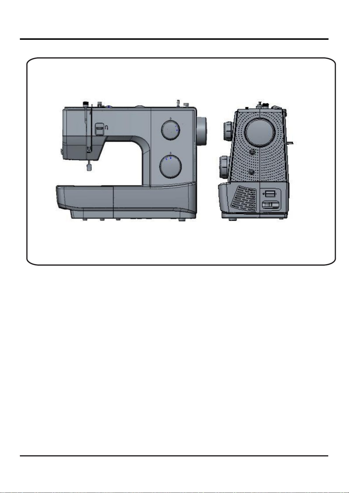
2.
Out
Look

4
3. Names of principal parts
1. Thread tension dial
2. Thread take-up lever
3. Presser foot pressure adjustment
4. Thread cutter
5. Presser foot
6. Needle plate
7. Sewing table and accessory box
8. Reverse sewing lever
9. Bobbin wider stopper
10.Stitch width dial (for sew&go 5)
11.Stitch length dial
12.Pattern selector dial
13.One step buttonhole lever
(for sew&go 5)
14.Automatic threader (optional)
15. Horizontal spool pin
16. Bobbin winder spindle
17. Hole for second spool pin
18. Handwheel
19. Power switch
20. Main plug socket
21. Bobbin thread guide
22. Upper thread guide
23. Face plate
24. Handle
25. Presser foot lifter
26. Foot control
27. Power cord

5
4. Removing methods of external parts
4-1 Face
plate
Remove the screw (a) and the face plate. ①
Face
plate
a
1
4-2 Free arm
cover
Remove the screw (b) and the free arm cover.
②
4-3 Base
plate
- Lay down machine. Remove 4 screws (c,
d,e,f).
- Remove the base plate. ③
c
d
Base
plate
e
f
3
4-4 Back
cover
- Remove the face plate, cap, free arm cover,
and base plate first.
- Lift spool rod and remove 4 screws (g,h,i,j).
- Loosen screw (k) about 3mm.
- Remove the back cover. ④
g
h
j
l
Back cover
k
4
a
b
c
f
d
i
j
k
e
g
h
①
②
③

6
4-5 Front
cover
- Loosen screw (l) about 3mm.
m
5
- Remove the screw (m) which deeply inside
the machine.
n
6
-Remove the pattern selector dial.
- Remove the front cover following direction of
arrow. ⑤
Pattern selector
dial
Front
cover
7
l
m
Selector dial
Selector dial
⑤

7
5. Adjusting methods of each part
5-1 Symbol
instructions
Noise occur while the machine is
running. Skip-over stitching, needle breakage,
and problems associated with needle.
Delivery of cloth to be in disorder and
insufficient, problems associated with
delivery amount.
Stitch tightening problem.
BH right and left stitching is not even,
incorrect length and problems
associated with buttonhole sewing.
Bobbin winding problem.
5-2 Play of arm
shaft
1) Remove the face plate, free arm cover,
base plate, back cover, front cover and
loosen screws (a, b) of arm shaft collar
(A). (1)
2) Pull hand wheel backward.
b
B
A
3) Push arm shaft collar (A) to left tightly
against arm shaft bushing (B). Then
fasten and secure screws (a, b). (1)
4) Be sure proper distance between arm a
shaft collar and arm shaft bushing. (2)
5) Be sure arm shaft operates smoothly 1
after adjustment.
6) Arm shaft collar and arm shaft bushing
being too tightly closed might cause
insufficient operation of arm shaft.
7) Follow steps 1, 2, 3 in order to re-adjust.
B
b
A
a
2
1
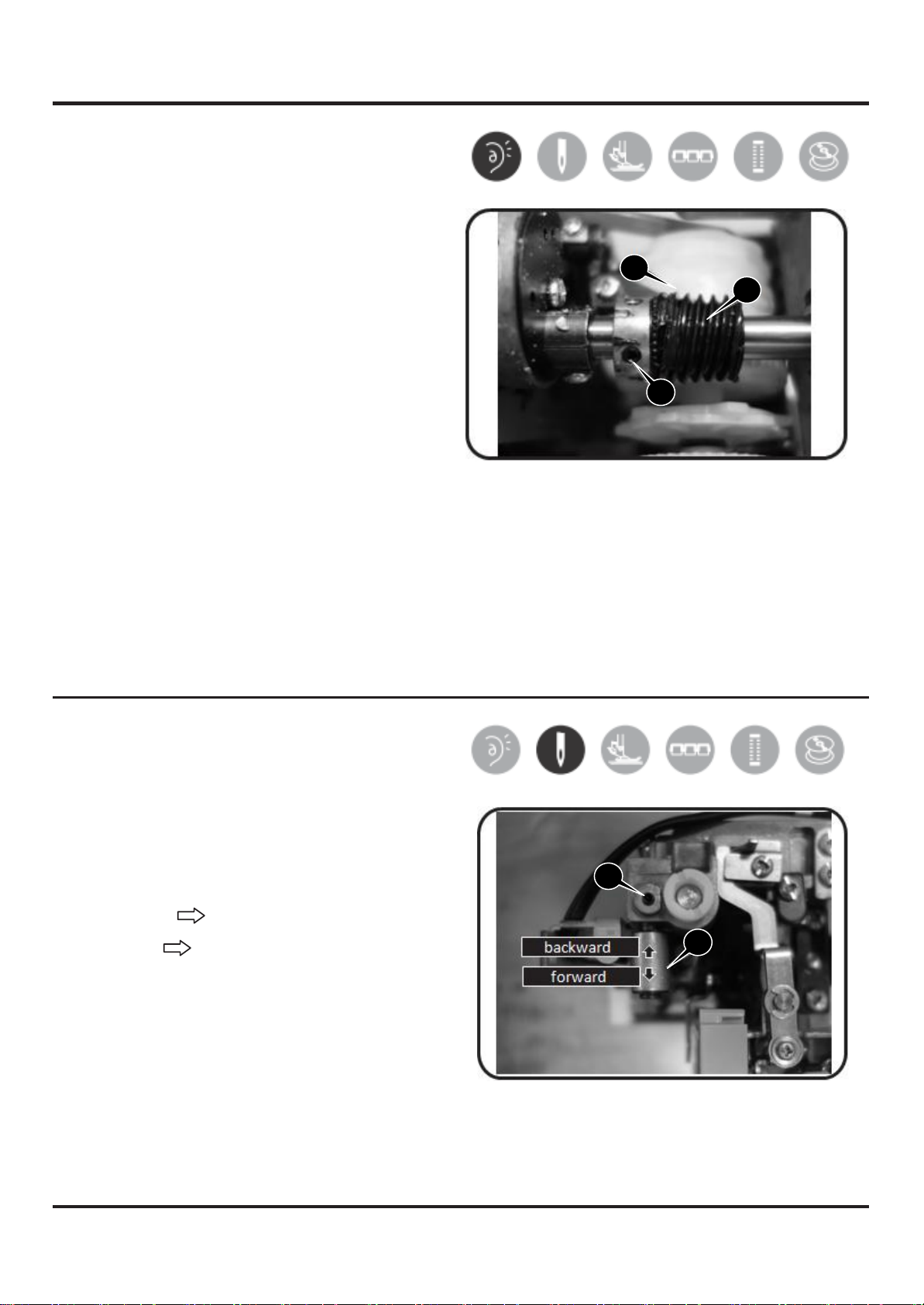
8
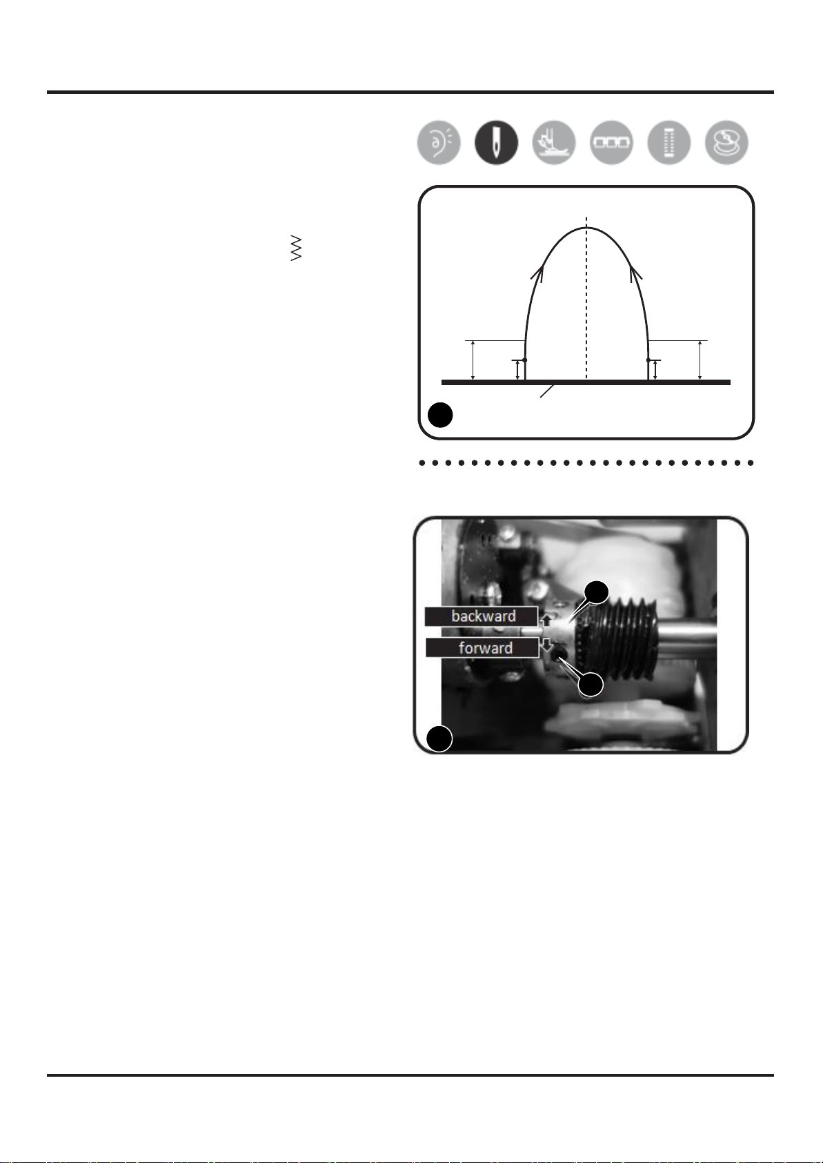
5-3 Play of arm shaft worm
and
pattern
cam
1) Remove the face plate, free arm cover,
base plate, back cover, front cover and
loosen screw (a) of arm shaft worm.
2) Push arm shaft worm (A) to right to
mesh with gear of pattern cam (B). Then B
A
fasten screw.
3) Confirm proper tightness by checking a
pattern cam gear's movement.
4) The insufficient tightness could be re-
adjusted by following steps 1, 2.
5) Re-confirm needle flow after above
adjustment is necessary.
5-4 Drop middle point of
needle
1) Remove the face plate.
2) Loosen screw (a) of needle bar
supporter. (A)
3) Turn needle bar supporter (A) forward /
backward to adjust needle.
Backward to move needle forward
Forward to move needle backward
4) Set needle position above center of
needle plate and fasten screw (a).
a
backward
A
forward
a
B
A
a
A

9
5-5 Height of presser
foot
1) Remove the face plate and lift up
presser bar lifter lever (A). (1)
2) Loosen screw (a) of presser bar bracket
with the hexagon screwdriver (3mm). (1)
3) Place gauge (B) (6.0 - 6.2mm) on top of
needle plate. (2)
A
a
4) Lift up presser bar lifter lever so bottom
of presser foot and top surface of gauge
would meet.
5) Secure tightly screw (a). 1
6) The correct setting of gauge should be
6.0 - 6.2mm.
B
2
A
a
B
2
1
10
5-6 Needle flow at maximum z
igzag
width
1) Remove the face plate, free arm cover,
base plate, back cover and front cover.
2) Set pattern selector dial to " ".
3) Set needle bar at its lowest point when it
swings to left. Turn hand wheel to move
the needle bar upward. The vertical
distance in which the needle point goes
up at the left position from the top of the
needle plate should be 3 - 5mm. (1)
5mm
3mm
3mm
5mm
4) If needle flow is less than 3mm, loosen
arm shaft worm screw (a) and turn arm
shaft worm (A) toward back. (2)
5) If needle flow is more than 6mm, turn
arm shaft worm (A) toward front. (2)
6) After adjustment. Secure tightly arm
shaft worm screw.
Needle
plate
1
a
7) To be sure arm shaft operate smoothly
after adjustment.
8) Otherwise, gearing match of arm shaft
worm gear and pattern cam gear could
be too big. To correct this problem,
follow adjustment 5-3. (P.S. Re-
adjustment of needle flow is necessary
after adjustment)
A
backward
forward
A
a
2
1
11
5-7 Drop middle point of
needle
1) Remove the face plate, free arm cover,
base plate and back cover first.
2) Set pattern selector dial to " ", stitch
width dial " " (for 3-dial model).
3) Loosen screw (a), than adjust screw unit
(b). (1)
4) clockwise needle moves left a
counter-clockwise needle moves right
b
Make sure needle drops on middle of 1
needle hole. (2)
5) Tighten srew (a).
Needle
hole
Needle
2
b
a
2
2
1

12
5-8 Needle
position
of
zigzag
1) Remove the face plate.
2) Set pattern selector dial to " ".
(maximum zigzag width)
3) Loosen nut (a) of the screw(b). (1)
4) Adjust needle by turning
clockwise / counter-clockwise. screw(b) a
b
5) Make sure needle drops on left / right of
needle hole with even distance to the
edge of needle hole. (2)
6) After adjusting, re-tighten nut (a). 1
Needle
Needle
hole
2
a
b
2
1

13
5-9 Height of needle
bar
1) Remove the face plate and free arm
cover.
2) Remove shuttle hook.
3) Place the gauge of diameter 23mm into
the center of the hook. (1).
4) Set needle at its lowest point,stop at
the position whan point of the needle
across the edge of the gauge. (1)
5) Loosen screw (a). (2)
6) Adjust height of needle by moving
needle bar (B) upward / downward.(2)
7) The correct setting of gauge should be
23mm.
8) After adjusting, re-tighten screw (a). a
B
2
a
B
2
1

14
5-10
Automatic
needle
t
h
reader
adjustment
1) Check the threader hook.
If it is damaged, change new one.
If it is inclined, adjust the threader hook
properly.
Needle
2) If the threader hook can not enter needle
hole freely, please adjust the threader
stopper. (1)
0.1mm
Threader
hook
3) Adjust the stopper: (2)
- Remove face plate and turn hand wheel
to raise needle bar to its highest position.
- Loosen screw (a) of the threader stopper 1
(A).
Threader
hook
- Move the stopper (A) upward and the
threader hook will become higher.
Move the stopper (A) downward and the
threader hook will become lower.
- Adjust the stopper to the proper position
A
for entering needle hole freely. a
- Fasten the screw (a).
2
A
a
2
1
15
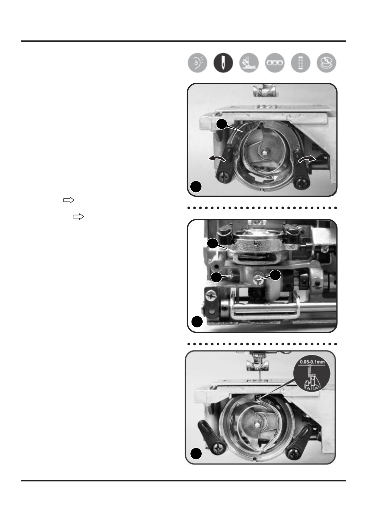
5-11
Distance-needle-hook
1) Remove the free arm cover.
2) Remove shuttle hook holder (A). (1)
3) Set needle at its lowest point when it
swings to right, stop at the position
when point of the needle and shuttle
A
hook will agree with.
4) Loosen screws (a, b) of open shuttle
race. (2)
5) Move shuttle race (B) upward/downward
to adjust movement. (2) 1
Upward tighten the distance
Downward lengthen the distance
6) Make sure space between needle and
tip of hook to be 0.05-0.1mm. (3)
B
7) After adjustment, re-tighten screws.
8) Re-assemble back shuttle hook holder. a
b
2
0.05-0.1mm
3
A
a
B
b
3
2
1
16
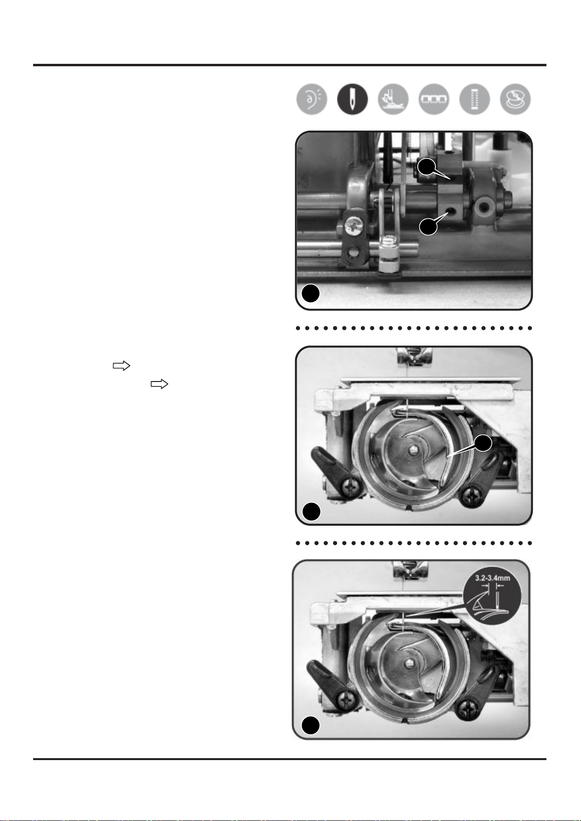
5-12 Timing of needle and
hook
1) Remove
plate. the free arm cover and base
2) Remove shuttle hook holder.
3) Set needle bar at its highest point and
b
loosen screw (a) of crank connecting
rod crank. (1)
4) Set needle bar at its lowest point when it
swings to left. a
5) Loosen another screw (b) of crank
connecting rod crank. (1)
6) Turn shuttle driver (A) to adjust timing of
needle and hook. (2) 1
7) Tighten two screws of crank connecting
rod crank when clearance between
point of hook and upper part of needle
eye is 3.2 - 3.4mm. (3)
Clockwise timing is smaller
Counterclockwise timing is bigger.
8) Re-assemble shuttle hook holder.
A
2
3.2-3.4mm
3
b
a
A
1
2
3

17
5-13 Distance
adjustment between
shuttle driver shaft
g
ear
complete and lower
s
haft
gear
complete
1) Remove free arm cover. Proceed to
loosen screw (a) and push feed lifting
rock cam (A) to right. (1)
A
2) Push lower shaft gear (B) to left tightly
against shuttle driver shaft gear
complete (C). (2) a
3) Push feed lifting rock cam (A) back
toward left and secure it tightly. 1
4) Avoid over-tightening shuttle driver shaft
gear complete and lower shaft gear
complete. If gearing match to be big,
then the torque will be bigger causing
shaking.
B
C
2
A
a
B
C
2
1

18
5-14 Play between shuttle
driver
shaft gear and lower
shaft
gear
1) Remove the face plate, free arm cover,
base plate, back cover and loosen
screws (a, b) of shuttle driver shaft gear
(A). (1)
A
2) Remove shuttle driver shaft gear (A). (1) a
b
3) Turn needle to its lowest point and when
rear end of shuttle driver shaft comes
across descending needle. In this
position face cut-facing side of shuttle
driver shaft to front. (2) 1
4) Re-assemble back shuttle driver shaft
gear, align shuttle driver shaft gear and
lower shaft gear (B) to mesh with each
other at one point (second teeth location)
(3).
5) Re-tighten screws of shuttle driver shaft
gear. Tighten first screw positioned at
cut-facing side of shuttle driver shaft.
6) Insert shuttle hook and check timing.
7) Re-assemble back shuttle driver shaft.
2
B
B
Keep two
teeth
unmeshed
Align to
mesh
with each
other
3 in this
point
A
a
b
B
B
3
2
1

19
5-15 Feed cam
position
adjustment
Problems associated with delivery amount,
stitch unbalance and needle breakage, make
the following adjustments:
1) Remove the face plate, free arm cover,
base plate, back cover and front cover.
2) Loosen screw (a) of feed cam at arm A a
shaft position. Make sure hair line
marking on feed cam (A) match
correctly with marking of arm shaft (B).
B
5-16 Feed
lifting
rock cam
position
adjustment
Problems associated with delivery amount,
stitch unbalance and needle breakage, make
the following adjustments:
1) Lift needle to its highest position.
B
2) Loosen screw (a) and make sure hair
line marking on feed lifting rock cam (A)
A
match correctly with marking of feed
lifting rock crank (B). (1) a
2
B
A
a
B
A
a
1
This manual suits for next models
3
Table of contents
Other EverSewn Sewing Machine manuals

EverSewn
EverSewn Hero User manual

EverSewn
EverSewn Maker 200 User manual

EverSewn
EverSewn CH04AX Operating instructions

EverSewn
EverSewn Sparrow QE User manual

EverSewn
EverSewn sparrow 15 User manual

EverSewn
EverSewn Sparrow X User manual

EverSewn
EverSewn Celine User manual

EverSewn
EverSewn sparrow 20 User manual


