EverSewn CH04AX Operating instructions

REPAIR MANUAL
CH04AX

Contents
1. Gauge & Tool List........................................................................................................................ 2
2. Remove machine covers....................................................................................................... 2
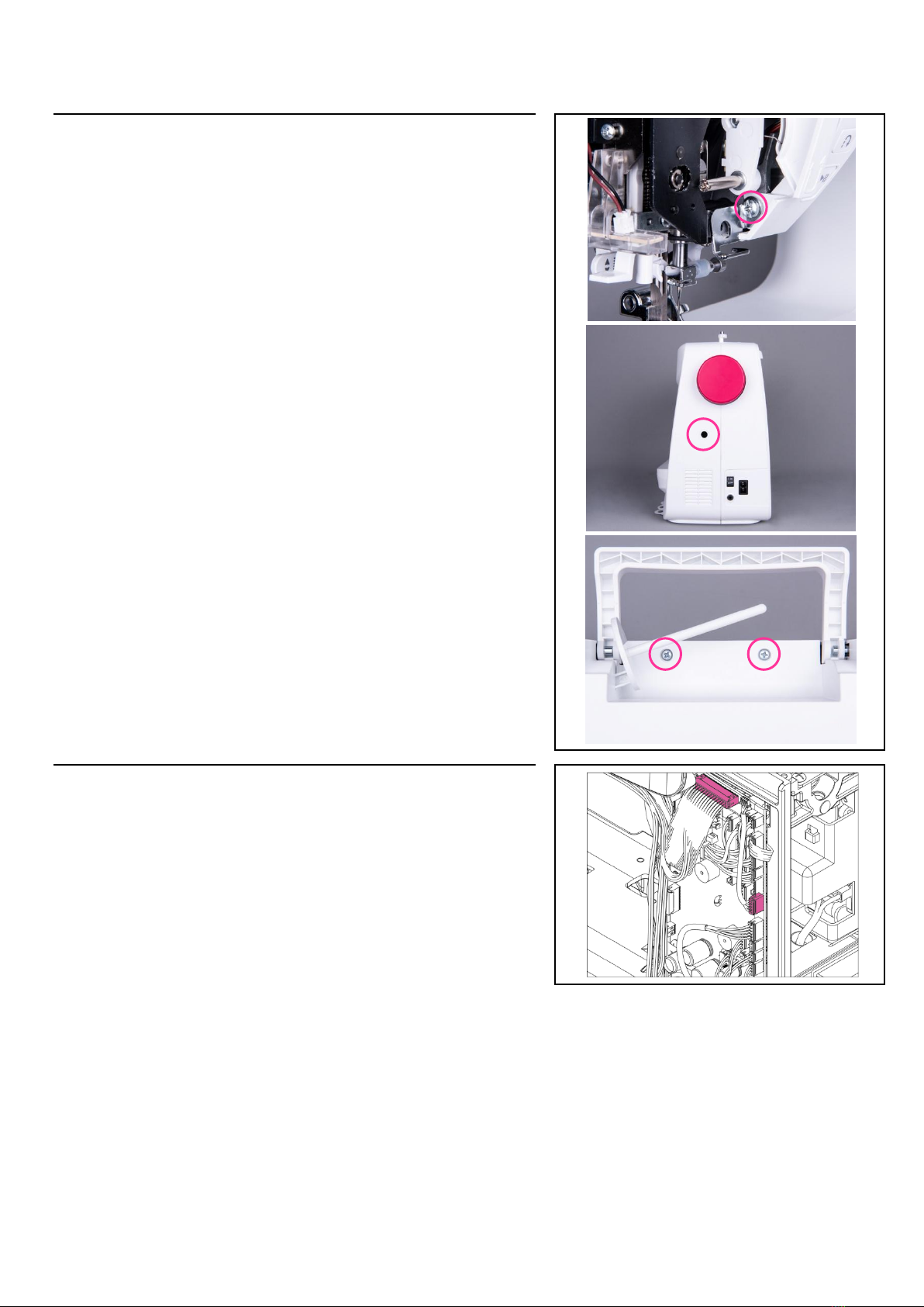
2-2. Remove face plate................................................................................................................................ 2
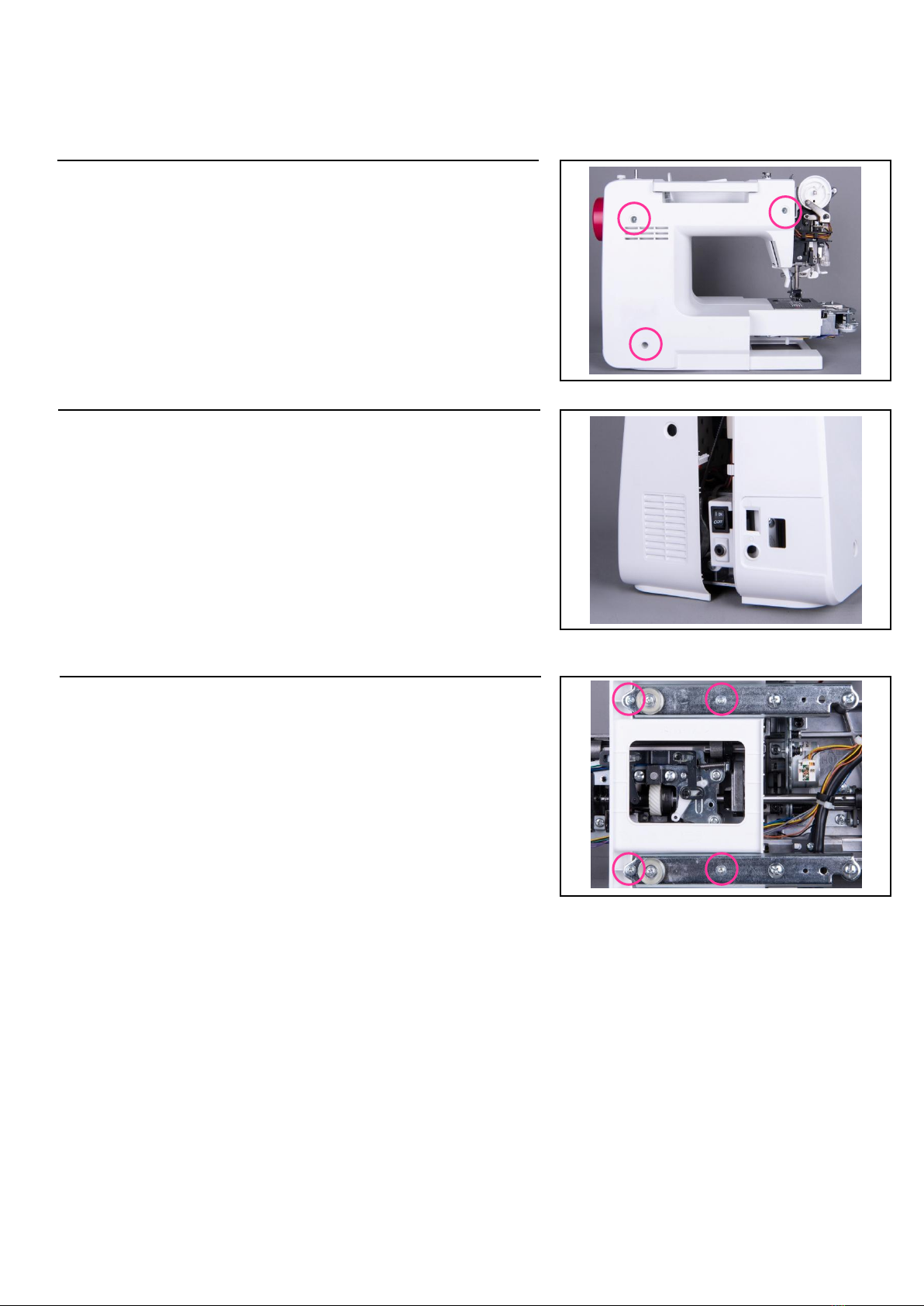
2-3. Remove Front cover ............................................................................................................................ 2
2-4. Remove Back cover............................................................................................................................. 2
2-5. Remove bed cover ............................................................................................................................... 2
3. Mechanical components adjustment........................................................................... 2
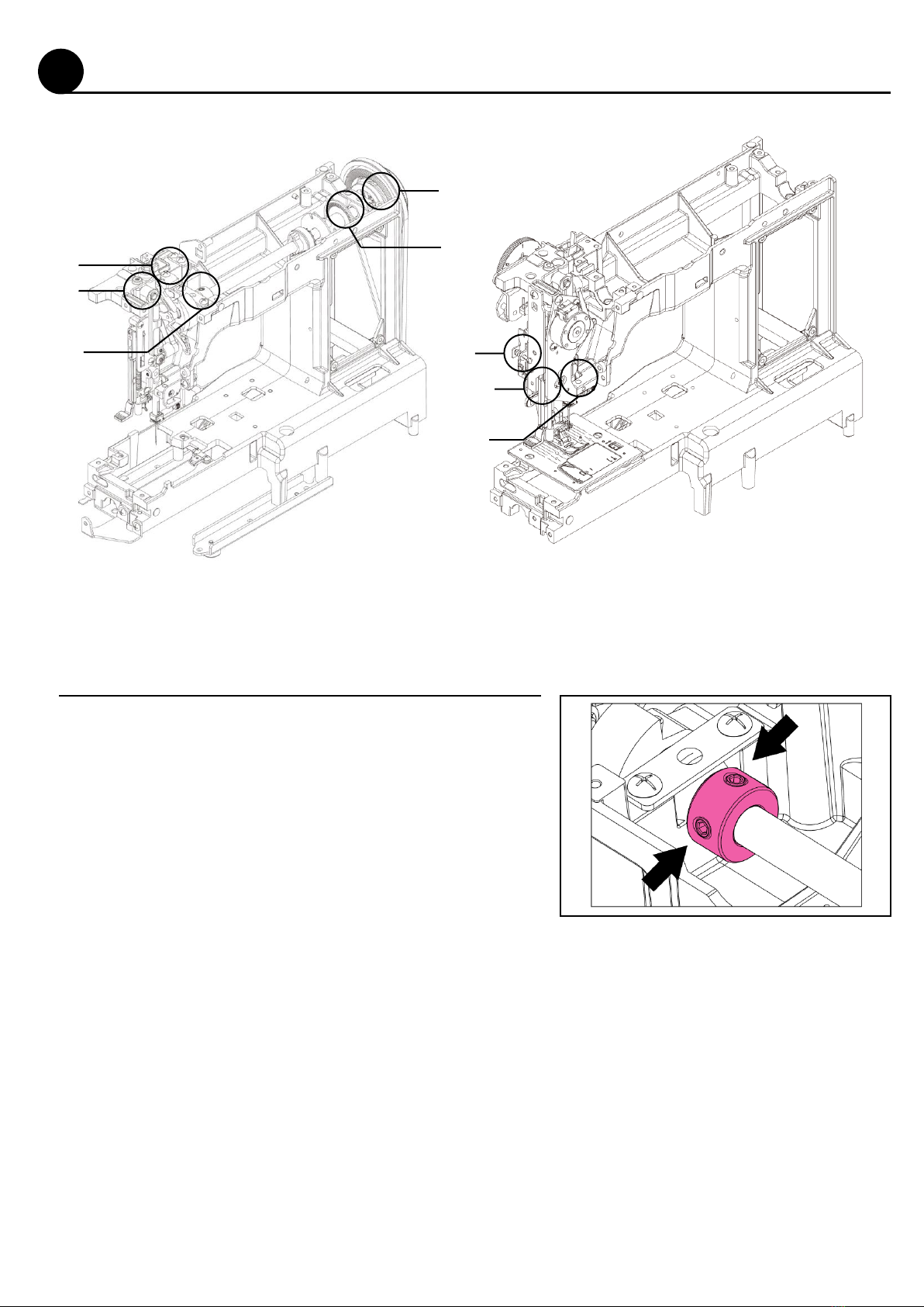
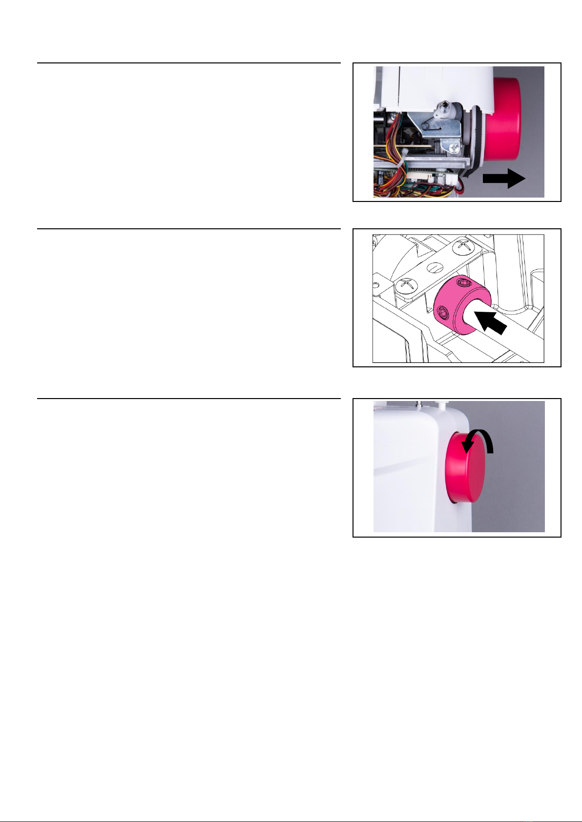
3-1. Play of the Arm shaft ........................................................................................................................... 2
3-2. Thread take up lever adjustment......................................................................................................... 2
3-3. Adjusting the needle drop position .................................................................................................... 2
3-4. Adjust height of the presser foot........................................................................................................ 2
3-5. Adjust the zigzag movement of the needle ........................................................................................ 2
3-6. Adjust needle drop positions.............................................................................................................. 2
3-7. Adjust the automatic needle threader ................................................................................................ 2
3-8. Adjust the needle bar height............................................................................................................... 2
3-9. Adjust the hook timing ........................................................................................................................ 2
3-10. Adjust the distance between needle and hook................................................................................ 2
3-12. Adjust the play for the rotary hook plates........................................................................................ 2
3-13. Adjust the height of the feed dog...................................................................................................... 2
3-14. Adjust the feed dog position............................................................................................................. 2
3-15. Adjust the upper thread tension ....................................................................................................... 2
3-16. Adjust the bobbin case tension ........................................................................................................ 2
3-17. Adjust motor belt ............................................................................................................................... 2
3-18. Super Adjust stitch balance.............................................................................................................. 2
3-19. BH BH adjustment.............................................................................................................................. 2
3-20. Bobbin winder adjustment ................................................................................................................ 2
4. Electronic Components.......................................................................................................... 2
5. Printed Circuit Board................................................................................................................ 2
5-2. HF transformer board .......................................................................................................................... 2
6-1. Trouble shooting –Main power .......................................................................................................... 2
6. Trouble shooting –Electronic parts............................................................................. 2
6-2. DC Trouble shooting - Motor............................................................................................................... 2
6-3. Trouble shooting –Stepping motor(stitch length)............................................................................. 2
6-4. Trouble shooting –Stepping motor(upper tension).......................................................................... 2
6-5. Trouble shooting –Stepping motor(thread trimmer)......................................................................... 2
6-6. Trouble shooting –Stepping motor(zigzag)....................................................................................... 2
6-7. Trouble shooting –Wi-Fi module (CH04AX) ....................................................................................... 2

6-8. Operation Panel Malfunction............................................................................................................... 2
6-9. Start/Stop button & Reverse button malfunction............................................................................... 2
6-10. Bobbin winder cannot stop............................................................................................................... 2
6-11. Buttonhole Sewing Failure................................................................................................................ 2
6-12. Foot Controller Failure....................................................................................................................... 2
6-13. LED Light Failure ............................................................................................................................... 2
6-14. Organize the cables ........................................................................................................................... 2
7. Embroidery Unit............................................................................................................................ 2
7-1. Main parts of the embroidery unit....................................................................................................... 2
7-2. Dissemble the embroidery unit........................................................................................................... 2
7-3. Mechanical adjustment for the embroidery unit. ............................................................................... 2
7-4. PCB Layout for the embroidery unit................................................................................................... 2
8. Quick Repair Reference.......................................................................................................... 2

1
1. Gauge & Tool List
Gauge Appearance
No
ZH SAP#
Item Description
Spec.
Purpose
1
031CAA0044
Needle bar height
gauge
29.05mm
For needle bar
height
adjustment (see
page 16)
2
031CAA0013
Hook timing gauge
3.5mm
For adjusting
the hook timing
(see page 18)
3
031CAA0014
Hook timing gauge
holder
For adjusting
the hook timing
(see page 18)
4
031CAA0010
Feed dog gauge
0.9~1.05mm
For adjusting
the height of
feed dog (see
page 25)
5
031V8D0301
Presser bar Gauge
6.0~6.5mm
For adjusting
the height of
presser foot
(see page 10)
6
031CAA0012
Zigzag movement
gauge
6.0~6.2mm
Checking the
zigzag
movement of
the needle (see
page10)
7
031CAA0042
Rotary hook plate
(1) gauge
0.3~0.5mm
Check the play
allowance for
the rotary hook
plate (1) (see
page 22)
8
031CAA0043
Rotary hook plate
(2) gauge
0.6~1.0mm
Check the play
allowance for
the rotary hook
plate (2) (see
page 23)

2
Tool Type
No
Head Type
Item Description
Specs
Remark
1
Hexagon
screwdriver
1.5mm
2
Hexagon
screwdriver
2.0mm
3
Hexagon
screwdriver
2.5mm
4
Hexagon
screwdriver
3.0mm
5
Hexagon
screwdriver
4.0mm
6
L-shape slotted
screwdriver (twin
heads)

3
2. Remove machine covers
2-1. Remove accessory box
2-1-1.
Grasp the accessory box then pull toward by the
arrow direction to remove it.
2-2. Remove face plate
2-2-1
Use Philips head screwdriver to remove the setscrews of the
face plate, free arm cover, free arm base cover and bed cover.

4
2-3. Remove Front cover
2-3-1
Use Philips screwdriver to remove the front cover
2-3-2
Remove the harness &WIFI module cable

5
2-4. Remove Back cover
2-4-1
Use Philips screwdriver to remove the back cover (Please
lower the presser foot lever first)
2-4-2
When removing the back cover, please pay attention to avoid
hitting the receptacle holder and break it.
2-5. Remove bed cover
2-5-1
Use Philips screwdriver to remove the bed cover

6
3. Mechanical components adjustment
①
②
③
④
⑤
⑥
⑦
⑧
3-1. Play of the Arm shaft
(※Please remove face plate, free arm cover, free arm base
cover, base cover, front cover in advance)
Use 2.5mm hexagon screwdriver to loosen 2 setscrews on arm
shaft collar (as shown in area ⑤).

7
3-1-2
Follow the arrow direction to pull the hand wheel
outward.
3-1-3
Pull arm shaft collar to left (as shown in area ⑤) and fit tightly
against the arm shaft bushing. Then tighten 2 setscrews on
the arm shaft collar
3-1-5
Follow 3-1-2 to pull the hand wheel outward and turn the
hand wheel to move the needle to three different positions
(highest, lowest, center). Then check if the play of the arm
shaft is sufficient.
3-1-4
Check if the arm shaft can rotate smoothly. If not, the arm
shaft collar may fit too tightly against the arm shaft bushing.
3-1-6
If the play of arm shaft is still too loose or too tight, follow the
above procedures (3-1-1~3-1-5) to re-adjust.

8
(※Please remove face plate, free arm cover, free arm base cover,
bed cover, front cover and back cover in advance)
3-2-1
Turn the hand wheel to check the noise location
3-2-2
Loosen the screw M4X8A (as shown in area ③) . Check and
adjust the tightness of thread take up lever supporter.
3-2-3
If it is set too tightly, the hand wheel will be difficult to turn.
3-2-4
On the contrary, if it is set too loosely, abnormal noise may occur
during operation.
3-2. Thread take up lever adjustment

9
3-3. Adjusting the needle drop position
(※Remove the face plate)
3-3-1
Select straight stitch pattern
3-3-2
Loosen the 2.0mm hex socket setscrew. (as shown in area
④)
3-3-3
Pull the needle bar supporter backward to move the needle
forward and vice versa. (as shown in area ④)
3-3-4
Adjust the needle position to the hole center of the needle
plate then tighten the setscrew. (as shown in area ④)

10
3-4. Adjust height of the presser foot
(※Remove the face plate)
3-4-1
Drop down the feed dog
3-4-2
Raise the presser foot lifter
3-4-3
Use a 2.0mm hexagon screwdriver to loosen the setscrew.
(as shown in area ⑥)
3-4-4
Put the gauge with the smaller side down below the presser
foot.

11
3-4-5
Adjust the presser bar position to make it fit against the
gauge.
3-4-7
Slightly tighten the hex socket setscrew. (as shown in area
⑥)
3-4-8
Use the gauge to check the height of the presser foot. By
the smaller side, the gauge can be put beneath the presser
foot
3-4-9
On the contrary, the taller side of the gauge cannot be put
beneath presser bar
3-4-10
If the height of the presser foot fits the standard, tighten
the hex socket setscrew firmly. (as shown in area ⑥)
3-4-6
Drop down the feed dog

12
OK
NG
3-5. Adjust the zigzag movement of the needle
(※Remove the face plate, free arm cover, free arm base cover,
bed cover and front cover)
3-5-1
Choose the stitch pattern “ ” ,and set the stitch width to 7mm
3-5-2
Set the needle position to its left lowest position.
Then turn the hand wheel to raise the needle and stop at the
point when it starts to move rightward.
At this point, the vertical distance between the needle tip and the
needle plate should be between 6.0~6.5mm.
3-5-3
If the vertical distance is less than 6mm, loosen the screw
M4*8Aon the rotary sensor collar first. (as shown in area ②)
Then turn the rotary sensor collar backward.
3-5-4
If the vertical distance is higher than 6.5mm, adjust the rotary
sensor collar position in reverse direction.
3-5-5
Re-check if the vertical distance fits to the standard.
If yes, tighten the screw M4*8Afirmly.
Note:
The presser foot should be aligned with the feed dog hole of
the needle plate without slanting.

13
3-6. Adjust needle drop positions
3-6-1
Choose the stitch pattern “ ” ,and set the stitch width to 7mm
3-6-2
Use a 1.5mm Hex screwdriver to loosen the setscrew of the
needle bar supporter. (as shown in area ⑦)
3-6-3
Turn setscrew (as the picture shown below) to adjust the
needle bar position. (as shown in area ⑧)
Turn the setscrew in clockwise direction will make the needle
position go left; Turn it in counterclockwise direction will go
right.
3-6-4
Make sure needle drop on the left / right of needle hole with
even distance to the edge of the needle hole then tighten the
setscrew.
(※Remove the face plate)

14
3-7. Adjust the automatic needle threader
3-7-2
Turn the hand wheel and move the needle to its highest
position.
3-7-3
Use a 1.5mm hex screwdriver to loosen the setscrew of
threader stopper.
3-7-4
Move the threader stopper upward to make the threader hook
go up.
3-7-5
Move threader stopper in another direction to make the
threader hook go down.
3-7-6
Adjust the threader stopper to the
correct position so as to let the
threader hook insert into the
needle eye smoothly.
(※Remove the face plate)

15
3-7-7
Tighten the threader stopper firmly and make sure the
threader stopper is not skewed.
3-8. Adjust the needle bar height
3-8-1
Remove the face plate
3-8-2
Move the needle to its center position
3-8-3
Use a flathead screwdriver to remove the needle plate.
3-8-4
Press the shank complete lever to release the presser foot
3-8-5
Take out the shuttle hook

16
3-8-5
Use a flathead screwdriver to loosen the needle clamp and
remove the needle.
3-8-6
Install the needle bar height gauge (29.05+/-0.05mm)
3-8-7
Turn the hand wheel to let needle go to its lowest position
3-8-8
When the needle is at lowest position, the gauge will slightly
touch the inner brink of the shuttle hook holder
3-8-8
If the needle bar height is set too high or low, use a 2.0mm hex
screw driver to loosen the setscrew for the needle bar bracket.
Then raise or lower the needle bar for adjustment.

17
3-9. Adjust the hook timing
3-9-1
Use a flathead screwdriver to remove the needle plate
3-9-2
Choose the stitch pattern “ ” ,and set the stitch width to 7mm
3-9-3
Turn the hand wheel to move the needle to the left side and
down to its lowest location
3-9-4
Install the timing gauge (3.5mm) and its holder then tighten the
setscrew.
3-9-5
Turn the hand wheel back and forth to make sure that the
gauge does not shake up and down.
Table of contents
Other EverSewn Sewing Machine manuals

EverSewn
EverSewn Sparrow QE User manual

EverSewn
EverSewn sparrow 15 Series Operating instructions

EverSewn
EverSewn Maker 200 User manual

EverSewn
EverSewn sparrow 15 User manual

EverSewn
EverSewn sparrow 20 User manual

EverSewn
EverSewn Hero User manual

EverSewn
EverSewn Celine User manual

EverSewn
EverSewn Sparrow X User manual
Popular Sewing Machine manuals by other brands

JANE
JANE Baby Lock A-LINE Series Instruction and reference guide

Brother
Brother ES-2000T Manuel d'instructions

Brother
Brother Cover Stitch Operation manual

Singer
Singer 138W102 Instructions for using and adjusting

Mitsubishi Electric
Mitsubishi Electric PLK-G3040R Technical manual

Singer
Singer Touch & Sew 758 instructions