EVGA Z390 DARK User manual

EVGA Z390 DARK (131-CS-E399)
-1 -
User Guide
EVGA Z390 DARK
Specs and Initial Installation

EVGA Z390 DARK (131-CS-E399)
- 2 -
Table of Contents
EVGA Z390 DARK ................................................................................................... - 1 -
Specs and Initial Installation..................................................................................... - 1 -
Before You Begin… ................................................................................................. - 4 -
Parts NOT in the Kit ............................................................................................................. - 5 -
Intentions of the Kit .............................................................................................................. - 5 -
Motherboard Specifications .................................................................................................. - 6 -
Unpacking and Parts Descriptions ........................................................................................ - 8 -
EVGA Z390 DARK Motherboard LED reference ............................................................. - 10 -
EVGA Z390 DARK Motherboard Component Legend ..................................................... - 14 -
PCIe Slot Breakdown ......................................................................................................... - 27 -
M.2 / U.2 Slot Breakdown .................................................................................................. - 27 -
Preparing the Motherboard ................................................................................................. - 28 -
Installing the CPU .............................................................................................................. - 28 -
Installing the CPU Cooling Device .................................................................................... - 29 -
Installing System Memory .................................................................................................. - 30 -
Installing the I/O Shield ...................................................................................................... - 31 -
Installing the Motherboard...................................................................................... - 31 -
Securing the Motherboard into a System Case ................................................................... - 32 -
Installing M.2 devices ............................................................................................. - 34 -
Installing M.2 Key-M Socket 3 Devices ............................................................................ - 34 -
Tested CPU and Memory ................................................................................................... - 36 -
Tested M.2 Key-M ............................................................................................................. - 37 -
Tested U.2........................................................................................................................... - 38 -
Tested M.2 Key-E............................................................................................................... - 38 -
Connecting Cables .............................................................................................................. - 39 -

EVGA Z390 DARK (131-CS-E399)
- 3 -
Onboard Buttons ................................................................................................................. - 49 -
First Boot ................................................................................................................ - 50 -
M.2 SSD, PCIe SSD, and NVMe SSD Installation steps ................................................... - 52 -
Internal RAID Controller ......................................................................................... - 54 -
Fan Header DC and PWM setup ........................................................................... - 89 -
Setting Up SLI and PhysX...................................................................................... - 93 -
Creative Labs Sound Blaster Pro Studio ............................................................................. - 97 -
EVGA NU Audio ................................................................................................... - 116 -
The NU Audio Control Panel ........................................................................................... - 119 -
NU Audio Custom Settings: ............................................................................................. - 127 -
Installing Drivers and Software ............................................................................ - 134 -
Windows 10 Driver Installation ........................................................................................ - 134 -
Warranty and Overclocking .............................................................................................. - 136 -
Troubleshooting ................................................................................................... - 137 -
Replacing a BIOS chip ..................................................................................................... - 137 -
Flashing the BIOS ............................................................................................................ - 140 -
Flashing the BIOS Without a CPU ................................................................................... - 143 -
SSD / HDD is not detected ............................................................................................... - 144 -
System does not POST, and POST code indicator reads “C” ........................................... - 146 -
System does not POST, and POST code indicator reads “55” ......................................... - 147 -
System does not POST, and POST code indicator reads “d7” ......................................... - 147 -
Have a question not covered above, or want some online resources? .............................. - 148 -
Multifunction LED indicator ............................................................................................ - 149 -
POST Beep codes ............................................................................................................. - 151 -
POST Port Debug LED .................................................................................................... - 152 -
POST Codes ........................................................................................................ - 153 -
EVGA Glossary of Terms ................................................................................................ - 158 -
Compliance Information ....................................................................................... - 161 -

EVGA Z390 DARK (131-CS-E399)
- 4 -
Before You Begin…
The EVGA Z390 DARK sets the standard for motherboards based on the
Intel®Z390 chipset. Much like the EVGA X299 DARK, its older brother, the
Z390 DARK is designed for ultra-enthusiasts looking to pull every last ounce of
performance from the new 9th Gen Intel®8-Core CPUs. The Z390 DARK
features a 17 Phase VRM design, along with two right-angle 8pin High Current
connectors to provide maximum power for overclocking. Two SMT DIMMs
enable high-frequency and low latency RAM overclocking. The 10-layer PCB is
studded with multiple sensors to track a variety of temperatures and voltages
across the board, which can be displayed on the dual-LED displays.
For its other features, the Z390 DARK contains Creative Audio with EVGA
NU Audio, two Intel®Gigabit NICs, mini-Display Port, onboard
power/reset/CMOS buttons, PCIe disable switches, triple BIOS support, 8
smart fan headers, and more swagger than any motherboard should have a right
to wield. If you’ve been holding out for a serious motherboard to upgrade, the
time has is at hand.
Lastly, a motherboard is only as good as its BIOS, and the EVGA Z390 DARK
features EVGA’s newest UEFI/BIOS GUI with a focus on overclocking and
functionality in a lean, straightforward package. You won’t need to be an expert
to configure your motherboard, but if you are, you’ll find features unavailable
anywhere else.

EVGA Z390 DARK (131-CS-E399)
- 5 -
Parts NOT in the Kit
This kit contains all the hardware necessary to install and connect your new
EVGA Z390 DARK Motherboard. However, it does NOT contain the
following items, which must be purchased separately in order to make the
system fully functional and install an Operating System:
Intel®Socket 1151 Processor
DDR4 System Memory
CPU Cooling Device
PCI Express Graphics Card
Power Supply
Hard Drive or SSD
Keyboard / Mouse
Monitor
(Optional) Optical Drive
EVGA assumes you have purchased all the necessary parts needed to allow for
proper system functionality. For a full list of supported CPUs on this
motherboard, please visit www.evga.com/support/motherboard
Intentions of the Kit
When replacing a different model motherboard in a PC case, you may need to
reinstall your operating system, even though the current HDD/SSD may
already have one installed. Keep in mind, however, you may sometimes also
need to reinstall your OS after a RMA even if your motherboard remains the
same due to issues that occurred prior to replacing the motherboard.

EVGA Z390 DARK (131-CS-E399)
- 6 -
Motherboard Specifications
Size:
EATX form-factor of 11.99 inches x 10.89 inches (304.5x276.6mm)
Microprocessor support:
Intel®Socket 1151 Processor
Operating Systems:
Supports Windows 10 64bit
System Memory support:
Supports Dual-Channel DDR4 up to 4600MHz+
Supports up to 32GB of DDR4 memory.
USB 2.0 Ports:
4x from Intel®Z390 PCH –4x internal via 2 FP headers
Supports transfer speeds up to 480 Mbps with full backwards compatibility
USB 3.1 Gen1 Ports:
4x from Intel®Z390 PCH –2x external, 2x internal via 1 FP headers
Supports transfer speeds up to 5Gbps with full backwards compatibility
USB 3.1 Gen2 Ports:
2x from ASMedia ASM3142 –6x external (1x Type-C, 5x Type-A),
1x Type-C internal with PD3.0 w/PPS and QC4.0
Supports transfer speeds up to 10Gbps with full backwards compatibility
*Type-C may require a Type-A adapter for backwards compatibility
SATA Ports:
Intel®Z390 PCH Controller
6x SATA 3/6 Gbit/s (600 MB/s) data transfer rate
- Support for RAID0, RAID1, RAID5, AND RAID10
- Supports hot plug
ASMedia ASM1061
2x SATA 3/6 Gbit/s (600 MB/s) data transfer rate -
- No RAID or Hot-Plug Support
Onboard Audio:
Creative Core3D Quad-Core Audio Processor (CA0132)
- Supports 5.1 Channel audio with Optical S/PDIF Out
EVGA NU Audio via the FP Audio header

EVGA Z390 DARK (131-CS-E399)
- 7 -
Onboard LAN:
1x Intel®i219V Gigabit (10/100/1000) Ethernet PHY
1x Intel®i210AT Gigabit (10/100/1000) Ethernet MAC+PHY
Ethernet Teaming Supported
Power Functions:
Supports ACPI (Advanced Configuration and Power Interface)
Supports S0 (normal), S3 (suspend to RAM), S4 (Suspend to disk - depends
on OS), and S5 (soft - off)
PCI Express Expansion Slots:
3x PCIe x16 slot 1x16/8*, 1x8/4*, 1x4*
1x PCIe x4 slot (via PCH)
*LANES PER SLOT CAN VARY BASED ON DEVICES INSTALLED.
PLEASE SEE PAGE 27 FOR LANE BREAKDOWN.
PCIe 3.0 Support:
Low power consumption and power management features
SLI and Crossfire Support:
2-Way SLI
3-Way Crossfire
Additional Expansion Slots:
2x M.2 Key-M 110mm slot PCIe/NVMe and Intel®Optane™
1x M.2 Key-E slot
1x U.2 slot
Single PS/2 port for keyboard or mouse
Fan Headers:
2x 4-pin PWM controlled headers (CPU1/CPU2)
6x 4-pin DC\PWM headers
All fans can be controlled via Smart Fan in the BIOS.
ALL FAN HEADERS HAVE A MAXIMUM POWER LIMIT OF 2 AMP
@ 12 VOLTS (24 WATTS) EXCEDING THIS LIMIT WILL CAUSE
IRREPARABLE DAMAGE TO THE BOARD.

EVGA Z390 DARK (131-CS-E399)
- 8 -
Unpacking and Parts Descriptions
The following accessories are included with the EVGA Z390 DARK
Motherboard:
EVGA Z390 DARK (131-CS-E399)
- 9 -
EVGA Z390 DARK (131-CS-E399)
- 10 -
EVGA Z390 DARK Motherboard LED
reference
The EVGA Z390 DARK Motherboard has several LEDs indicating power, connectivity,
and activity. Below is the location of the LEDs and their function.
EVGA Z390 DARK (131-CS-E399)
- 11 -
1. M.2 Key-M Socket3 110mm (PM1)
a. WHITE: M.2 can be used.
2. Multifunction POST Indicator
a. During boot it will cycle many different hexadecimal post codes with a
range of 00-FF and this indicates what aspect of the Power On Self Test
(POST) is currently running.
i. For a list of POST Codes, please see Page 153.
b. This indicator can be configured in BIOS to display hardware monitoring
information, such as voltage or temperature. After boot, these LEDs will
show either temperature or voltage, depending on user configuration in
the BIOS.
3. Memory DIMM 2 Status
a. WHITE: DIMM detected and present
RED: DIMM/Memory has failed POST
4. Memory DIMM 2 Status
a. WHITE: DIMM detected and present
b. RED: DIMM/Memory has failed POST
5. +5V Standby Power
a. WHITE: Voltage present (Does not mean PSU is outputting in-spec,
only that this specific voltage is detected)
6. CATERR - Catastrophic Error on the processor
a. RED: Processor error has occurred.
b. OFF: No error state detected in the CPU.
1. M.2 Key-E Enabled 12. VPLL_OC Status 23. M.2 Key-M PM1 Enabled
2. Multi-function POST indicator 13. VCCST Status 24. U.2 PU1 Status
3. Memory DIMM 2 Status 14. Power Button 25. U.2 PU1 Enabled
4. Memory DIMM 1 Status 15. Reset Button 26. PE2 Status
5. +5V Standby Power 16. BIOS 1 Active 27. PE2 Enabled
6. CATERR 17. BIOS 2 Active 28. M.2 Key-M PM2 Status
7. VCORE Status 18. BIOS 3 Active 29. M.2 Key-M PM2 Enabled
8. VDIMM Status 19. SW Slow Mode ON 30. PE3 Status
9. VSA Status 20. PE1 Status 31. PE3 Enabled
10. VCCIO Status 21. PE1 Enabled 32. PE4 Status
11. VCCPLL Status 22. M.2 Key-M PM1 Status 33. PE4 Enabled
LED Legend

EVGA Z390 DARK (131-CS-E399)
- 12 -
7. VCORE status
a. WHITE: Voltage present (Does not mean PSU is outputting in-spec,
only that this specific voltage is detected)
8. VDIMM status
a. WHITE: Voltage present (Does not mean PSU is outputting in-spec,
only that this specific voltage is detected)
9. VSA Status
a. WHITE: Voltage present (Does not mean PSU is outputting in-spec,
only that this specific voltage is detected)
10. VCCIO Status
a. WHITE: Voltage present (Does not mean PSU is outputting in-spec,
only that this specific voltage is detected)
11. VCCPL Status
a. WHITE: Voltage present (Does not mean PSU is outputting in-spec,
only that this specific voltage is detected)
12. VPLL_OC Status
a. WHITE: Voltage present (Does not mean PSU is outputting in-spec,
only that this specific voltage is detected)
13. VCCST Status
a. WHITE: Voltage present (Does not mean PSU is outputting in-spec,
only that this specific voltage is detected)
14. Power Button
a. RED: Motherboard is turned on and running.
15. Reset Button
a. WHITE: Reset button will typically flash in conjunction with HDD/SSD
LED. Depending on load, the button may flash or appear solid white at
times.
b. NVMe SSDs cannot be read for the purposes of the Reset LED.
16. BIOS1 Active LED
a. WHITE: Active BIOS Chip (only 1 will be lit at a time)
17. BIOS2 Active LED
a. WHITE: Active BIOS Chip (only 1 will be lit at a time)
18. BIOS3 Active LED
a. WHITE: Active BIOS Chip (only 1 will be lit at a time)
19. SW Slow Mode ON
a. WHITE: Slow Mode switch has been set to enabled
20. PCIe Status for PE1. The LED will remain off when this PCIe slot is disabled
or unpopulated.
a. WHITE: PE1 slot can be used with installed CPU.

EVGA Z390 DARK (131-CS-E399)
- 13 -
21. PCIe Enabled for PE1. The LED will remain off when this PCIe slot is disabled
or unpopulated.
a. GREEN: PE1 device present and detected.
22. M.2 Key-M Socket3 110mm (PM1) Status LED. The LED will remain off when
this PCIe slot is disabled or unpopulated.
a. WHITE: PM1 slot can be used with installed CPU.
23. M.2 Key-M Socket3 110mm (PM1) Enabled LED. The LED will remain off
when this PCIe slot is disabled or unpopulated.
a. GREEN: PM1 device present and detected.
24. U.2 PU1 Status
a. WHITE: Port is enabled.
b. OFF: No device is attached/Port is disabled.
25. U.2 PU1 Enable
a. GREEN: Port is connected to a working device.
b. OFF: No device is attached/Port is disabled.
26. PCIe Status for PE2. The LED will remain off when this PCIe slot is disabled or
unpopulated.
a. WHITE: PE2 slot can be used with installed CPU.
27. PCIe Enabled for PE2. The LED will remain off when this PCIe slot is disabled
or unpopulated.
a. GREEN: PE2 device present and detected.
28. M.2 Key-M Socket3 110mm (PM2) Status LED. The LED will remain off when
this PCIe slot is disabled or unpopulated.
a. WHITE: PM2 slot can be used with installed CPU.
29. M.2 Key-M Socket3 110mm (PM2) Enabled LED. The LED will remain off
when this PCIe slot is disabled or unpopulated.
a. GREEN: PM2 device present and detected.
30. PCIe Status for PE3. The LED will remain off when this PCIe slot is disabled or
unpopulated.
a. WHITE: PE3 slot can be used with installed CPU.
31. PCIe Enabled for PE3. The LED will remain off when this PCIe slot is disabled
or unpopulated.
a. GREEN: PE3 device present and detected.
32. PCIe Status for PE4. The LED will remain off when this PCIe slot is disabled or
unpopulated.
a. WHITE: PE4 slot can be used with installed CPU.
33. PCIe Enabled for PE4. The LED will remain off when this PCIe slot is disabled
or unpopulated.
a. GREEN: PE4 device present and detected.

EVGA Z390 DARK (131-CS-E399)
- 14 -
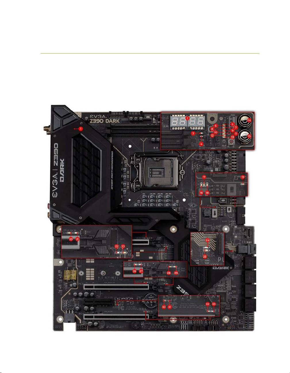
EVGA Z390 DARK Motherboard Component
Legend
The EVGA Z390 DARK Motherboard with the Intel®Z390 and PCH Chipset.
Figure 1 shows the motherboard and Figure 2 shows the back panel connectors
FIGURE 1. Z390 DARK Motherboard Layout
EVGA Z390 DARK (131-CS-E399)
- 15 -
**For a FULL description of the above legend, please see Page 17.
1. CPU Socket 1151 13. M.2 Socket 3 Key-M 110mm (PM2) 25. Front Panel Audio Connector
2. Intel Z390 PCH (Southbridge) 14. PCIe Slot x16/x8 26. Front Panel Connectors
3. PWM Fan Headers (2 amp) 15. PCIe Slot x8/x4 27. Removable BIOS Chip
4. PWM/DC Fan Headers (2 amp) 16. PCIe Slot x4 28. BIOS Selector Switch
5. DDR4 Memory DIMM Slots 1, 2 17. PCIe Slot x4 (x16 Mechanical) 29. CMOS Battery
6. 24-pin ATX power connector 18. Power Button 30. PCIe Disable Switches
7. 8 pin EPS Power Connector 19. Reset Button 31. ProbeIt Headers
8. Supplemental PCIe 6 pin power 20. CMOS Reset Button 32. PC Speaker
9. Intel Sata 6G RAID Ports 21. Multi-function POST indicator 33. BIOS Safeboot Button
10. ASMedia Sata 6G Ports 22. USB 3.1 Gen1 Header 34. USB 2.0 to SPI for BIOS Flash
11. U.2 (SFF-8639) Port 23. USB 3.1 Gen2 Type-C Header 35. SW Slow Switch
12.
M.2 Socket 3 Key-M 110mm (PM1)
24. USB 2.0 Headers 36. Rear Panel I/O (Figure 2)
Component Legend

EVGA Z390 DARK (131-CS-E399)
- 16 -
Figure 2. Chassis Rear Panel Connectors
1.
PS/2 (Keyboard or Mouse)
5.
Intel i210V NIC
9.
USB 3.1 Gen2 Type-C
2.
USB 3.1 Gen1
6.
Intel i219AT NIC
10.
Analog Audio Jacks
3.
Intel 9560 WiFi/BT
7.
USB 3.1 Gen2 Type-A
11.
Optical Out
4.
BIOS/CMOS Reset
8.
Mini-DisplayPort 1.2
I/O Hub
Analog Audio Port Breakdown 2/2.1 Channel 4.0/4.1 Channel 5.1 Channel
Dark Green Head Phone Head Phone Head Phone
Front Speaker / Front Speaker/ Front Speaker/
Speaker+Sub Out Speaker+Sub Out Speaker+Sub Out
Pink Mic / Line In Mic / Line In Mic / Line In
Black Rear Speaker Out Rear Speaker Out
Orange Center/Voice channel
Light Green

EVGA Z390 DARK (131-CS-E399)
- 17 -
Component Legend Descriptions
1. CPU Socket 1151
This is the interface for the Central Processing Unit (CPU), and supports 8th
and 9th Gen. Intel Core i3, i5, i7 and i9 models compatible with the Intel®
LGA1151 Socket, based on Coffee Lake-S architecture. Intel®Xeon®E
processors are not supported.
2. Intel®Z390 PCH (Southbridge)
The Platform Controller Hub (PCH) handles the role that was previously held
by the South Bridge. The PCH allocates bandwidth to smaller PCIe slots, M.2,
USB, audio, etc. In simplified terms, the PCH works as a hub for peripherals
that are less bandwidth-intensive.
3. PWM Fan Headers
4-pin fan headers that control the fan speed based on a configurable curve or
static percentage. PWM (Pulse-Width Modulation) works by pulsing power to
the fan at a constant rate and sending the RPM signal to the fan’s controller via
a Sense cable, rather than adjusting fan speed by increasing and decreasing
voltage. This method is preferable because it eliminates voltage-based fan stall
points. Please see Page 89 for more in-depth PWM breakdown and PWM
controls within BIOS/UEFI. These fans can be controlled via Smart Fan or
manually within the BIOS.
4. DC/PWM Fan Headers
These ports may be used with both DC and PWM fans, and may be controlled
via Smart Fan or manually within the BIOS.
5. DDR4 Memory Slots
The memory slots support up to two 288-pin DDR4 DIMMs in Dual-Channel
mode. Dual-Channel mode will be enabled only upon using two or four sticks
of supported memory, according to the installation guide above; using one or
three sticks of memory will lower the board to Single-Channel mode, which
may significantly lower performance. 32GB of RAM is supported in a 2x16GB
configuration; 32GB modules are *NOT* officially supported. At the time of
this manual’s release, this motherboard officially supports up to 4600MHz+
speeds. These speeds cannot be guaranteed, however, because Intel®only
certifies the speed of the memory controller up to 2666MHz for Coffee Lake-S
processors.

EVGA Z390 DARK (131-CS-E399)
- 18 -
6. 24-pin ATX power connector
The main power for the motherboard is located on the right side of the board
and parallel to the PCB; this is also described as a “90 degree / right-angle”
connector (See Page 40 for more specifics to the connector itself, and associated
wiring/pinouts). The 24-pin connector IS directional and the connector needs
the tab on the socket to line up with the release clip located on the 24-pin
connector from the power supply. This connector pulls the bulk of the power
for all components; other connectors, such as CPU +12V EPS, PCIe (video
card AND motherboard sides), have been added to reduce the load and increase
longevity due to wiring and trace limitations.
7. Dual 8-pin EPS Connector
The +12V EPS are comprised of 90 degree right-angle dual-dedicated power
inputs for the CPU (See Page 41 for more specifics to the connector itself, and
associated wiring/pinouts). Carefully choose the correct power cable by
consulting with the installation manual for your power supply. This connector
is designed only to work with an EPS or CPU cable. System builders may make
the mistake of plugging in a PCIe 8-pin or 6+2-pin connector, which will
prevent the board from POSTing and possibly short or damage the board.
Although the cables appear similar, they are wired differently and attaching a
PCIe cable to an EPS connector may cause damage to the motherboard.
Alternatively, if no power cable is connected or detected, the system will not
POST and will hang at POST code “C.”
8. Supplemental PCIe 6-pin Power Connector
There is a 6-pin PCIe connector at the bottom of the motherboard (See Page 40
for more specifics to the connector itself, and associated wiring/pinouts). This
connector provides dedicated power to the PCIe x16 slots, augmenting the
+12V power provided by the 24-pin and the GPU directly.
This is optional for a single card solution, but is recommended for SLI, CFX,
and dual-processor video cards.
9. Intel®SATA 6Gbit/s Ports
The Intel®Z390 PCH has a 6-port SATA 3/6 Gbit/s controller (See Page 48
for specifics on the connectors). This controller is backwards compatible with
SATA and SATA II devices, and supports SSDs, HDDs and various types of
optical devices (CDROM, DVDROM, BD-ROM, etc). The controller also

EVGA Z390 DARK (131-CS-E399)
- 19 -
supports NCQ, TRIM, hot swap capability (provided the proper HDD/SSD
bays/racks are installed), and RAID levels 0/1/5/10.
10. ASMedia SATA 6Gbit/s Ports
This is a secondary SATA controller, the ASM1061 is a 2-port SATA3/6
Gbit/s controller with legacy support for older operating systems. This is
included largely for benchmarking and overclocking with very specific
programs, such as Super Pi, 3DMark, PCMark, etc. This board is not
guaranteed to fully support any OS prior to Windows 10 x64, as we offer no
drivers for legacy OS (See Page 48 for specifics on the connectors).
11. U.2 Port (SFF-8639)
U.2, originally known as SFF-8639, is a high bandwidth connection specifically
engineered for next generation SSDs. U.2 brings PCIe x4 (Gen3) NVMe
performance to a 2.5” SSD form factor and provides a solution to potential
heating problems that may be present in some M.2 solutions. Port function
depends on installed CPU-type and BIOS Configuration.
12. M.2 Socket 3 Key-M 110mm (PM1)
M.2 is an SSD form factor standard, which uses up to four PCIe lanes and
utilizes Gen3 speeds. Most popularly paired with NVMe SSDs, this standard
offers substantially faster transfer speeds and seek time than SATA interface
standards. All M.2 devices are designed to connect via a card-bus style
connector and be bolted into place and powered by the connector, rather than
by a dedicated data cable and power cable.
This socket will support Key-M devices of 110mm, 80mm, 60mm, and 42mm
length.
This connector can utilize only PCIe/NVMe-based M.2 SSDs, or Intel®
Optane™NVMe devices.
13. M.2 Socket 3 Key-M 110mm (PM2)
M.2 is an SSD form factor standard, which uses up to four PCIe lanes and
utilizes Gen3 speeds. Most popularly paired with NVMe SSDs, this standard
offers substantially faster transfer speeds and seek time than SATA interface
standards. All M.2 devices are designed to connect via a card-bus style
connector and be bolted into place and powered by the connector, rather than
by a dedicated data cable and power cable.
This socket will support Key-M devices of 110mm, 80mm, 60mm, and 42mm
length.

EVGA Z390 DARK (131-CS-E399)
- 20 -
This connector can utilize only PCIe/NVMe-based M.2 SSDs, SATA M.2, or
Intel®Optane™NVMe devices.
14. PCIe Slot x16/x8*
PCIe x16/x8 slots are primarily used for video cards. These full-length slots
will provide 8 or 16 lanes of bandwidth to a full-size card, and are backwards-
compatible with x8, x4, and x1-length cards.
Coffee Lake-S has 16 PCIe lanes available for routing.
15. PCIe Slot x8/4*
PCIe x8/4 slot can be used for video cards or other devices. PE2, the only
x8/x4 slot on the board, receives either x8 lanes or x4 from the CPU (Page 27),
depending upon the peripheral configuration. These full-length slots will
provide up to 8 lanes of bandwidth to a full-size card, and are backwards-
compatible with x8, x4, and x1-length cards.
Coffee Lake-S has 16 PCIe lanes available for routing.
16. PCIe Slot x4*
PCIe x4 slot PE3 uses up to 4 Gen 3 lanes from the PCH. This slot is typically
used for sound cards, WiFi, USB, LAN or other peripheral cards. Using this slot
will have no effect on the bandwidth or throughput of the x16 slots used for
SLI because this slot uses only PCH bandwidth.
17. PCIe Slot x4* (x16 Mechanical)
PCIe x4 slot can be used for video cards or other devices. PE4, the only full
x16 mechanical slot that runs at x4 electrically, receives either x4 lanes or x0
from the CPU (Page 27), depending upon the peripheral configuration. These
full-length slots will provide up to 4 lanes of bandwidth to a full-size card, and
are backwards-compatible with x1-length cards.
PCIe x4 slot PE4 uses up to 4 Gen 3 lanes from the CPU. This slot shares 4
lanes with PE2, and will change both PE2 and PE4 to x4 lanes. Using this slot
will disable SLI because SLI requires at least 2 slots capable of x8 bandwidth.
Coffee Lake-S has 16 PCIe lanes available for routing.
18. Power Button
This is an onboard power button, and may be used in place of, or in
conjunction with, a front panel power button wired to the board.
Benching systems, or test benches before final assembly, are best served by
using the onboard power because it removes the need to wire a Power/Reset
Table of contents
Other EVGA Motherboard manuals

EVGA
EVGA nForce 750i SLI User manual

EVGA
EVGA X99 FTW User manual

EVGA
EVGA EVGA X79 DARK User manual

EVGA
EVGA nForce 122-CK-NF68-XX User manual

EVGA
EVGA P67 FTW User manual

EVGA
EVGA 270-SE-W888-KR User manual

EVGA
EVGA X58 SLI3 User manual

EVGA
EVGA X58 SLI LE User manual

EVGA
EVGA X58 3X SLI User manual

EVGA
EVGA P55 FTW 200 User manual

EVGA
EVGA Z590 DARK User manual

EVGA
EVGA H370 Stinger User manual

EVGA
EVGA Classified SR-2 Super Record 2 System manual

EVGA
EVGA Z87 User manual

EVGA
EVGA Z87 System manual

EVGA
EVGA X58 FTW User manual

EVGA
EVGA Z170 STINGER User manual

EVGA
EVGA 131-GT-E767-KR User manual

EVGA
EVGA EVGA X79 DARK System manual

EVGA
EVGA 141-GT-E770-A1 User manual


