EVGA nForce 3 250 User manual


2
Copyright © 2005 EVGA.com Corporation – All Rights Reserved
COPYRIGHT OF THIS MANUAL BELONGS TO THE MANUFACTURER. NO PART OF THIS MANUAL,
INCLUDING THE PRODUCTS AND SOFTWARE DESCRIBED IN IT MAY BE REPRODUCED,
TRANSMITTED OR TRANSLATED INTO ANY LANGUAGE IN ANY FORM OR BY ANY MEANS WITHOUT
WRITTEN PERMISSION OF THE MANUFACTURER.

3
Table of Contents
Overview.....................................................................................5
Motherboard Features.......................................................................5
Preparing Your Computer..................................................................6
Package Contents.............................................................................6
Product Specifications.............................................................. 7
Chapter 1....................................................................................8
Layout Diagram and Jumper Settings ...............................................8
Jumpers........................................................................................9
Connectors ...................................................................................9
Headers......................................................................................10
Expansion Sockets.....................................................................10
Chapter 2..................................................................................11
Hardware Installation.......................................................................11
Hardware installation Steps........................................................11
Checking Motherboard’s Jumper Setting....................................11
Installing the AMD Athlon64 754-pin CPU..................................13
Installing the Memory..................................................................13
Installing Expansion Cards .........................................................15
Assigning IRQs for Expansion Card ...........................................15
Interrupt Request Table for This Motherboard............................16
AGP Slot.....................................................................................17
Connectors and Headers............................................................18
Starting Up Your Computer .............................................................26
Chapter 3..................................................................................27
BIOS Introduction............................................................................27
Entering the BIOS Setup.................................................................27
Getting Help Once Inside the BIOS Setup..................................27
BIOS Setup Main Menu...................................................................28
Standard CMOS Features...............................................................29
Advanced BIOS Features................................................................31
Advanced Chipset Features ............................................................34
Integrated Peripherals.....................................................................36
Onboard IDE Function................................................................36
Onboard Device Function...........................................................38

4
Onboard Super IO Function........................................................39
Init Display First..........................................................................40
Power On Function.....................................................................40
PWR Status after PWR Failure...................................................40
Power Management Setup..............................................................41
PnP/PCI Configuration Setup..........................................................43
PC Health Status.............................................................................45
Clock/Voltage Control......................................................................46
Load Standard and Optimized Defaults...........................................48
Set Supervisor/User Passwords......................................................48
Save & Exit Setup/Exit Without Saving............................................48
Chapter 4..................................................................................49
Motherboard Device Drivers............................................................49
Chapter 5..................................................................................50
Glossary..........................................................................................50
Chapter 6..................................................................................51
Useful Information ...........................................................................51
Contacting Customer Service.....................................................51
Information to keep handy before calling....................................51
Compliance Information...................................................................52
FCC Compliance Information......................................................52
CE Compliance Information........................................................52
Legal Information.............................................................................52
Software License Agreement......................................................52
Trademark Information ...............................................................52
Warranty Information.......................................................................53

5
Overview
Thank you for purchasing a genuine EVGA® motherboard. EVGA is an
NVIDIA® Select Solution Provider that builds high performance 3D
accelerators and motherboards based on reference designs by the
NVIDIA Corporation. Your new EVGA motherboard is fully capable of
supporting DPMS (energy savings) and DDC-2B (plug and play)
functions.
Motherboard Features
This motherboard supports 64-bit AMD® Athlon64™ and Sempron™
processors (K8 Processors). The NVIDIA NForce3 250 Chipset delivers
a high performance and professional desktop platform solution which
utilizes the Socket 754 design. The memory size on this motherboard is
expandable to 2.0GB.
The EVGA motherboard uses the newest NVIDIA N Force3 250 Chipset
which supports an 800MHz system bus. The motherboard provides
133MHz, 166MHz and a 200MHz Memory clock frequency which
supports DDR266, DDR333 and DDR400 DDR Module. The
motherboard offers ULTRA ATA 133 and Serial ATA RAID 0, RAID 1,
RAID 0+1 functions to provide faster HDD performance throughout to
boosts overall system performance.
The nForce3 has an integrated LAN chip that supports 10, and
100 Mbps data transfer rate for full and half duplex operation.
An integrated on-board 6-channel AC’97 CODEC is fully compatible
with Sound Blaster Pro that gives the best sound quality and
compatibility.
For those wanting even greater graphics performance, the 115-K8-
NF33is outfitted with an AGP slot supports AGP 8X/4X capability and
Fast Write Transactions.
This motherboard provides high performance and meets future
specification demands. It is wise choice for your computing needs.

6
Preparing Your Computer
WARNING: Turn off the power to your system and discharge your
body’s static electric charge by touching a grounded surface – for
example, the metal surface of the power supply – before performing any
hardware procedure. EVGA assumes no liability for any damage,
caused directly or indirectly, by improper installation of any components.
If you do not feel comfortable performing the installation, consult a
qualified computer technician. Damage to system components, such as
the motherboard or graphics card, and injury to yourself may result if
power is applied during installation. Now that you have prepared your
computer, you are ready to install your motherboard.
Package Contents
EVGA Motherboard
Driver Install CD
I/O shield for ATX case
IDE data cable (2)
Floppy drive data cable
Serial ATA data cable (2)
User Guide

7
Product Specifications
Spec Description
Design ATX form factor 4 layer PCB, size 30.4x21.0cm.
Chipset NVIDIA nForce3 250single Chipset.
CPU Socket 754
Support 64bit AMD Athlon64 754-Pin package utilizes Flip-
Chip Pin Grid Array package processor
Support CPU Frequency 800MHz
Support up to 3200+ ~ 4000+ processor
Reserves support for future AMD Athlon64 Sempron 754-pin
processors
Memory Socket 184-pin DDR Module socket x 2
Support 2pcs DDR266/DDR33/DDR400 DDR Modules
Expandable to 2.0GB
Expansion Slot AGP slot x1 support AGP 2.0 & AGP 3.0 for 4X/8X mode
32-bit PCI slot x5
IntegratedIDE and
Serial ATA RAID
Two PCI IDE controllers support PCI Bus Mastering, ATA
PIO/DMA and the ULTRA DMA 33/66/100/133 functions that
deliver the data transfer rate up to 133 MB/s; Two Serial
ATA ports provide 150 MB/sec data transfer rate for two
Serial ATA Devices and offer RAID 0, RAID1, RAID 0+1
functions
10/100 LAN Integrated LAN chip
Support Fast Ethernet LAN function provide 10/100
Mb/s data transfer rate
Audio AC’97 Digital Audio controller integrated
6-channel AC’97 Audio CODEC on board
Audio driver and utility included
BIOS Award 2MB Flash ROM
Multi I/O
PS/2 keyboard and PS/2 mouse connectors
Floppy disk drive connector x1
Parallel port x1
Serial port x2
USB2.0 port x 4 and headers x 4 (connecting cable option)
Audio connector (Line-in, Line-out, MIC)
Design ATX form factor 4 layers PCB size: 30.4x21.0cm


9
Jumpers
Connectors
Jumper Name Description Page
JP5 CMOS RAM Clear 3-pin Block 11
JP1 Keyboard Power On
Enabled/Disabled 3-pin Block 12
JP2/JP6 USB Power On Enabled/Disabled 3-pin Block 12
Connector Name Description Page
PWR ATX Power Connector 20-pin Block 18
ATX12V ATX 12V Power Connector 4-pin Block 19
KB1 PS/2 Mouse & PS/2 Keyboard
Connector 6-pin Female 19
USB1/USB2 USB Port Connector 4-pin Connector 19
LAN LAN Port Connector RJ-45 Connector 19
PARALLEL Parallel Port Connector 25-pin Female 19
CN1 Audio Connector 3 phone jack Connector 19
COM1/COM2 Serial Port COM1/COM2
connector 9-pin Connector 19
FDD Floppy Driver Connector 34-pin Block 20
IDE1/IDE2 Primary/Secondary IDE
Connector 40-pin Block 21
SATA1/SATA2 Serial ATA IDE Connector 7-pin Connector 21

10
Headers
Expansion Sockets
Header Name Description Page
AUDIO SPEAKER, MIC header 9-pin Block 22
USB3
USB4 USB Port Headers 9-pin Block 22
SPEAK PC Speaker connector 4-pin Block 23
PWR LED Power LED 3-pin Block 23
FP
(Power
LED/Reset/
IDE LED/Power
Button)
Front Panel Header (including
Power LED/ IDE activity
LED/Reset Switch / Power On
Button lead)
9-pin Block 23
SYSFAN1
SYSFAN2
CPUFAN
FAN Headers 3-pin Block 24
CDIN CD Audio-In Headers 4-pin Block 24
SPDIF SPDIF Connector 9-pin Block 25
Socket/Slot Name Description Page
ZIF Socket 754 CPU Socket 754-pin mPGAB
Athlon64 CPU Socket 13
DIMM1
DIMM2 DDR Module Socket 184-pin DDR Module
Socket 14
PCI1∼PCI5 PCI Slot 32-bit PCI Local Bus
Expansion slots 15
AGP AGP 4X/8X Mode Slot AGP Expansion Slot 16

11
Chapter 2
Hardware Installation
Hardware installation Steps
Before using your computer, complete the following steps:
1. Check the motherboard jumper settings.
2. Install the CPU, heatsink and fan.
3. Install the system memory (DIMM).
4. Install any expansion cards that are to be used in the system.
5. Connect the IDE and floppy cables as well as the front and
back panel cables.
6. Connect ATX power supply cable.
7. Power-On and load the standard default motherboard settings.
8. Reboot the system.
9. Install the Operating System.
10. Install any drivers and utility software as needed.
Checking Motherboard’s Jumper Setting
9JP5 – CMOS RAM Clear (3-pin)
A battery must be used to retain the motherboard configuration in
CMOS RAM short 1-2 pins of JP5 to store the CMOS data.
To clear the CMOS, follow the procedure below:
1. Turn off the system and unplug the AC power
2. Remove ATX power cable from ATX power connector
3. Locate JP5 and short pins 2-3 for a few seconds
4. Return JP5 to its normal setting by shorting pins 1-2
5. Connect ATX power cable back to ATX power connector
Note: The CMOS should be cleared when troubleshooting, forgetting
a password or after over clocking and the system failed to boot.
CMOS RAM Clear Setting
2-3 closed Clear CMOS
JP5
1 3
JP5
1 3
1-2 closed Normal

12
9JP1 – Keyboard Power On function Enabled/Disabled
9JP2, JP6 – USB Power On function Enabled/Disabled
Keyboard/USB Power On Setting
2-3 closed - KB Power
ON Enabled
JP1 1
3
JP1 1
3
1
-2 closed - KB Power
O
N Disable (Default)
2-3 closed USB
Power On Enabled
JP2 1
3
JP2 1
3
1
-2 closed USB Power
O
N Disable (Default)
USB Power On Settin
g
2-3 closed USB
Power On Enabled
JP6 1 3
JP6 1 3
1-2 closed USB Power
ON Disable (Default)

13
Installing the AMD Athlon64 754-pin CPU
This motherboard provides a 754-pin surface mount, Zero Insertion
Force (ZIF) socket, referred to as the mPGA754 socket which supports
the AMD Athlon64 processor in the 754 Pin package utilizes Flip-Chip
Pin Grid Array package technology.
The CPU that comes with the motherboard should have a cooling FAN
attached to prevent overheating. If this is not the case, purchase the
correct cooling FAN before turning on the system.
WARNING: Be sure that there is sufficient air circulation across the
processor’s heatsink. In addition, ensure the CPU cooling FAN is
working correctly; otherwise it may cause the processor and
motherboard to overheat which could cause damage to the system.
An auxiliary cooling FAN may be installed if necessary.
To install the CPU, follow the procedures below:
1. Turn off your system and remove its cover.
2. Locate the ZIF socket and open it by first pulling the lever
sideways away from the socket then upward to a 90-degree
angle.
3. Insert the CPU with the correct orientation as shown below.
4. Replace the lever to its original position.
Note: Locate the notched corner and place the CPU in the socket
accordingly. Because the CPU has a corner pin for two of the four
corners, the CPU will only fit in the orientation as shown.
Installing the Memory
This motherboard has two 184-pin DDR Dual Inline Memory Modules
(DIMM) slots for DDR memory. The minimum memory size for this
motherboard is 64MB and expands to a maximum memory size of
2.0GB of DDR SDRAM.
CPU ZIF mPGAB Socket
Golden Arrow
Socket 754

14
Valid Memory Configurations:
Installing DDR SDRAM modules in to the motherboard is generally
easy; however, if you need assistance, refer to the illustration below.
Note: When you install DIMM modules fully into the DIMM socket,
the eject tab should be locked into the DIMM module and fit into its
indention on both sides.
WARNING: The DDR SDRAM CLOCK is set at 200MHz; use only
DDR400 compliant DDR Modules. If non-compliant DIMM modules
are used, the system may not boot because of the strict timing
requirements. If the DDR Modules are not DDR400 compliant, set
the SDRAM clock to 133MHz to ensure system stability.
Bank 184-pin DDR DIMM PCS Total Memory
Bank 0, 1
(DIMM1) DDR266/DDR333/DDR400
DDR DRAM Module X1 64MB∼1.0GB
Bank 2, 3
(DIMM) DDR266/DDR333/DDR400
DDR DRAM Module X1 64MB∼1.0GB
Total System Memory (Max. 2.0GB) X2 64MB∼2.0GB
DIMM2 (BANK2+BANK3)
DIMM1 (BANK0+BANK1)

15
Installing Expansion Cards
WARNING: Turn off the power to the system when adding or
removing expansion cards or any other system components.
Failure to do so may cause severe damage to the system.
Installation Procedures:
1. Read the documentation that came with the expansion card and
make any necessary hardware or software setting changes for the
expansion card. A good example is jumper setting changes.
2. Remove the computer’s cover and the bracket plate on the slot
you intend to use.
3. Align the card’s connectors and press it in firmly.
4. Secure the card in the slot with the screw that was removed from
the bracket plate.
5. Replace the computer system’s cover.
6. Set up the BIOS if necessary.
7. Install any necessary software drivers for the new expansion card.
Assigning IRQs for Expansion Card
Some expansion cards need an IRQ to operate. Generally, an IRQ must
exclusively be assigned to the expansion card for it to work properly. In
a standard design, there are 16 IRQs available but most of them are
already in use.

16
9- These IRQs are usually available for ISA or PCI devices.
IRQ Priority Standard function
0 N/A System Timer
1 N/A Keyboard Controller
2 N/A Programmable Interrupt
3 98 Communications Port (COM2)
4 99 Communications Port (COM1)
5 96 Sound Card (sometimes LPT2)
6 911 Floppy Disk Controller
7 97 Printer Port (LPT1)
8 N/A System CMOS/Real Time Clock
9 910 ACPI Mode when enabled
10 93 IRQ Holder for PCI Steering
11 92 IRQ Holder for PCI Steering
12 94 PS/2 Compatible Mouse Port
13 N/A Numeric Data Processor
14 95 Primary IDE Channel
15 91 Secondary IDE Channel
Interrupt Request Table for This Motherboard
Slot INT A INT B INT C INT D INT E INT F INT G INT H
Slot 1 9
Slot 2 9
Slot 3
9
Slot 4
9
Slot 5
9
Onboard USB 1
9
Onboard USB 2
9
AC97/MC97
9
IMPORTANT! If using PCI cards on shared slots, make sure that the
drivers support “Shared IRQ” or that the cards do not need an IRQ
assignment. If conflicts arise between the two PCI groups, it will make
the system unstable or cards inoperable.

17
AGP Slot
This motherboard is equipped with an AGP
Slot that supports 8X/4X AGP VGA cards.
AGP SLOT
2X 4X

18
PIN ROW1 ROW2
1 3.3V 3.3V
2 3.3V -12V
3 GND GND
4 5V Soft Power On
5 GND GND
6 5V GND
7 GND GND
8 Power OK -5V
9 +5V (for Soft Logic) +5V
10 +12V +5V
Pin 1
Connectors and Headers
Connectors
PWR: Power Connector (20-pin block)
ATX Power Supply Connector – The motherboard is setup for soft
power on by using the momentary switch that connects from the front
panel switch to the 2-pin Power On jumper on the motherboard. When
the power switch on the back of the ATX power supply is turned on, the
full power will not come into the system board until the front panel
switch is momentarily pressed. Pressing the switch again will turn off the
power to the motherboard.
ATX12V: ATX 12V Power Connector (4-pin block)
This motherboard has a supplemental power connector that delivers an
additional 12V volts for processors that require additional power. If the
4-pin power connector is not connected to the motherboard, the system
can become unstable and not function properly.
Pin 1

19
KB1: PS/2 Mouse & PS/2 Keyboard Connector
These are connectors for the PS/2 keyboard and the PS/2 Mouse.
USB1/USB2: USB Port connector
These are 4-pin connectors that connect USB devices to the system
board.
LAN: LAN Port connector
This is a standard RJ45 connector which allows connectivity to a
network.
PARALLEL: Parallel Port Connector (25-pin female)
The Parallel Port connector is a 25-pin D-Subminiature Receptacle
connector. The On-board Parallel Port can be disabled through the
BIOS SETUP. Please refer to INTEGRATED PERIPHERALS SETUP
section for more detail information.
CN1: AUDIO (LINE-OUT, LINE-IN, MIC): Audio and Game Connector
Line-Out: Audio output to speakers.
Line-In: Audio input to the sound chip.
MIC: Connects a Microphone to the system
COM1/COM2: Serial Ports
These are 9-pin D-Subminiature male connectors. The On-board serial
ports can be disabled through the BIOS SETUP MENU. Please refer to
the INTEGRATED PERIPHERALS SETUP section for more details
regarding this information.
PRINT LAN
USB1
USB2
PS/2Mous
PS/2 KB
MIC
LINE-OUT
LINE-IN
COM2
COM1

20
Floppy Drive Connector
Pin 1
FDD
Primary IDE
Connecto
r
Pin 1
IDE1
FDD: Floppy drive Connector (34-pin block)
This connector supports the 3 ½ inch floppy drive ribbon cable. Use the
cable provided to connect the floppy drive to the system motherboard.
IDE1: Primary IDE Connector (40-pin block)
This connector supports the IDE1 hard disk ribbon cable. Use the cable
provided to connect the primary hard drive to the system motherboard.
Note: If two hard disks are installed, the second drive must configured
as a slave by setting its jumpers accordingly. Please refer to the
documentation of the hard disk for the correct jumper settings.
Table of contents
Other EVGA Motherboard manuals
EVGA
EVGA X299 Micro User manual
EVGA
EVGA 141-LF-E658 User manual

EVGA
EVGA 111-CD-E630 User manual

EVGA
EVGA Z87 CLASSIFIED User manual

EVGA
EVGA nForce 132-YW-E180 User manual

EVGA
EVGA SR-3 DARK User manual
EVGA
EVGA Z75 SLI User manual
EVGA
EVGA nForce 780i SLI FTW User manual
EVGA
EVGA Z75 SLI User manual
EVGA
EVGA 141-LF-E658-KR - P55 FTW 200 Motherboard User manual
EVGA
EVGA Z370 MICRO User manual
EVGA
EVGA X99 User manual
EVGA
EVGA nForce 780i SLI FTW User manual
EVGA
EVGA nForce 750i SLI User manual
EVGA
EVGA 113-YW-E115-TR User manual
EVGA
EVGA P67 FTW User manual
EVGA
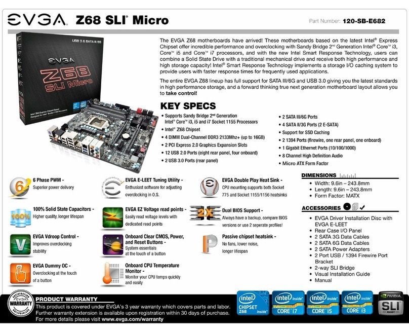
EVGA Z68 SLI Micro User manual
EVGA
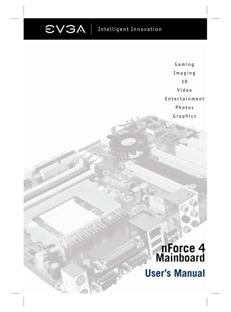
EVGA NFORCE4 123-K8-NF47-XX User manual
EVGA
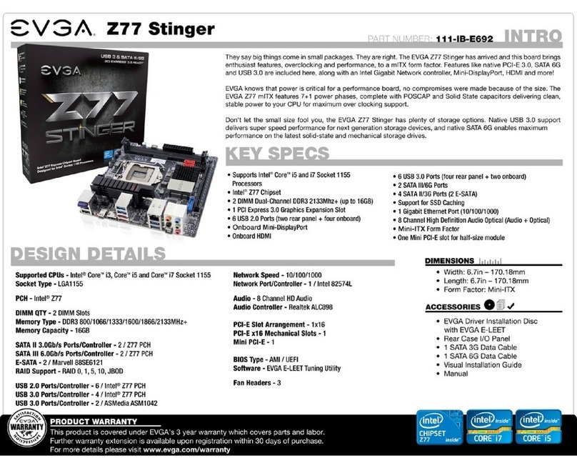
EVGA Z77 Stinger System manual
EVGA
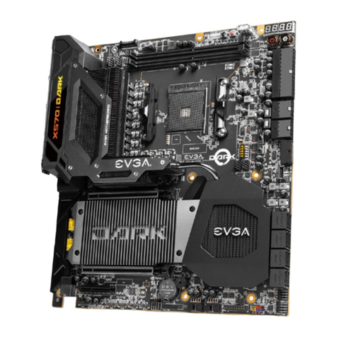
EVGA X570 User manual
