EVIE EVIECSP732SHA User manual
EVIE Smart Home Charging Installation Manual
Product Code: EVIECSP732SHA
Type 2, Mode 3, Single Phase 7.2KW 32A
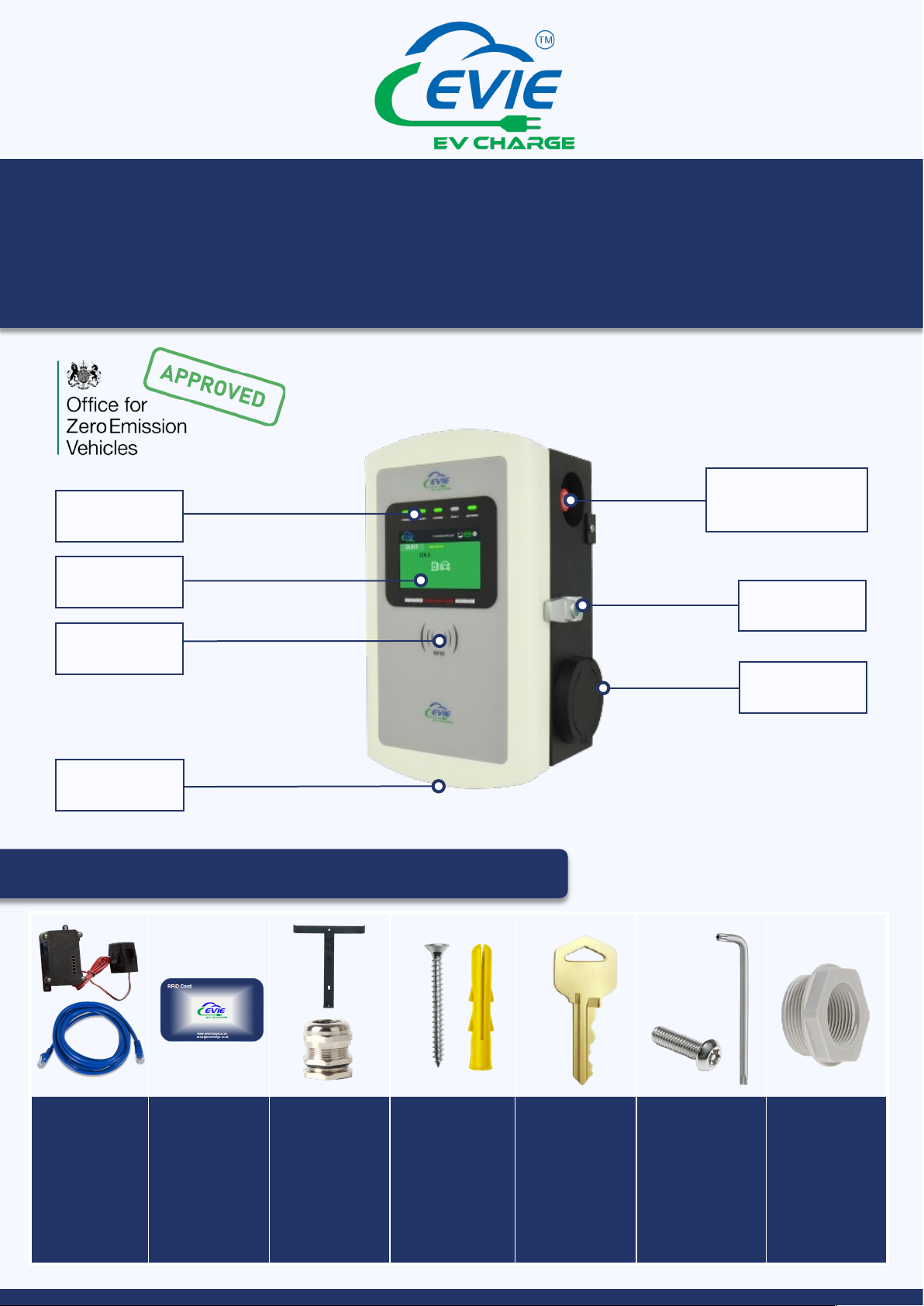
LED Indicators
RFID Swipe
LED Display
Cable Entry
Emergency Stop
Button
Key Lock
Type 2 Socket
Accessories Supplied in Box
1x CT Clamp via
RS485 Modbus
& CAT5
3x RFID Cards
(Customer to
finish pairing)
1x Wall
Mounting
Bracket
1x Cable Gland
M32 &
Locknut
3x Wall Plugs
and CS Screws
(No. 8
recommended
40mm long)
2x Keys for
Enclosure
Lock
3x Security
Screws
1x Security Key
1x 32mm to
25mm Plastic
Reducer
1x 32mm to
20mm Plastic
Reducer

2

Overview
3
Page
Unit Installation Guide 4-6
Internet Connection Instructions 7
Pheilix App Instructions 8-12
Important Safety Instructions 13

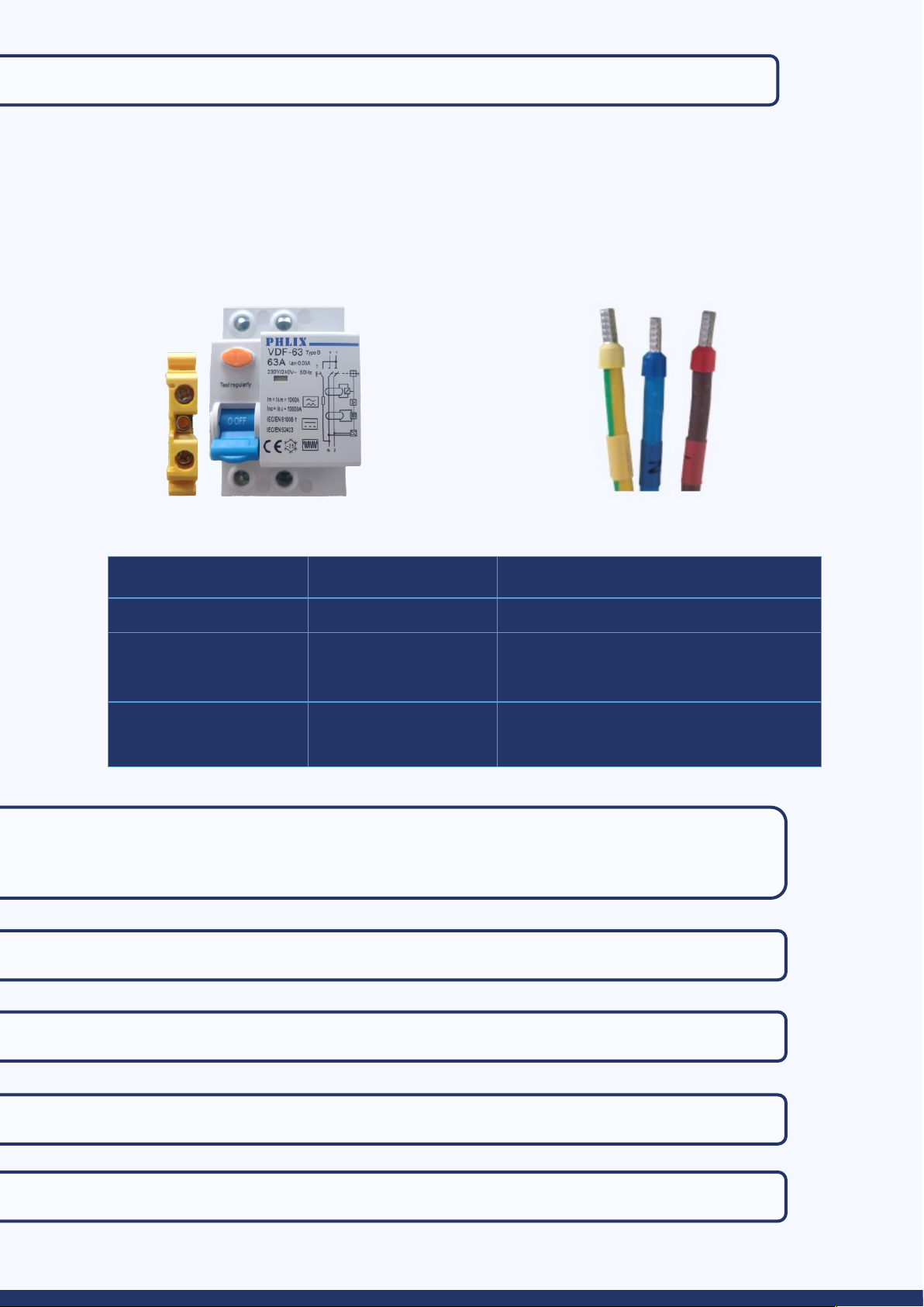
Power Cables
The unit can be installed using a suitable 6mm² three core cable
Live supply = Brown Neutral cable = Blue PE cable = Green/Yellow
Unit Installation Guide
Step 1: Attach the mounting bracket to the wall or the ground mounting pole
Wall mounting:
• Please ensure the unit bracket is fixed to an exterior brick wall or suitable wooden
frame
• Choose a suitable location for the unit by checking the signal on a mobile phone to
ensure a Wi-Fi connection can be established. Should the signal strength not be
sufficient, the system may require a Wi-Fi booster or hard-wired RJ45
• Put the bracket on the wall, mark the wall where the holes are indicated
• Drill holes into the wall on the marked position, place the wall plugs provided into the
drilled holes
• Place the bracket back to the wall and insert the CS screws into the wall plug
• Fix the EV charger unit onto the bracket and ensure the holes on the enclosure body
match the holes on the bracket (The enclosure and bracket have 3 holes, 2 on each side
and 1 on the bottom)
• Insert the security screws into the assembly holes and fix the screws using the
security key provided
• Use the key to open the enclosure box
4
Ground mounting pole:
• Drill 4 holes in the ground using a 12mm diameter percussion drill (Position according to
the image below). The depth of the hole should be 80mm
• Install expansion bolts (M8*100) to fix the pole
• Using M5*8 screws, fix the bracket on the pole
• Using M5*10 security screws, fix the box on the bracket (On the sides and the bottom of the
unit)
270mm
90mm
Step 2: Connect the power cables (Live, Neutral and Earth)
• The unit requires an available 40amp dedicated supply from your consumer unit
• Ensure the supply cable is not live and is disconnected
• Connect the power cables via the cable gland to the indicated input position below
• On the Type B RCD you will see an ‘L’ and ‘N’ marked (See image below)
• Tighten the Live, Neutral and PE cables firmly into the corresponding terminal connectors
(3NM recommended)
Step 3: Tighten the cable gland with the locknut to ensure the input cables
are fixed well
Step 4: Check the RCD unit is ‘ON”
Step 5: Lock the enclosure
Step 6: Connect the input cable to the dedicated supply on the consumer unit
Step 7: Check the emergency stop button is at a normal open status
5
PE NL
Items Cable Torque Value/ NM
Type B RCD 3 NM
MID Meter Communication Cable
L, N Cable
0.25 NM
2 NM
AC Contactor A1, A2
L, N Cable
1.2 NM
2.5 NM
Recommended Torque Values

CT Clamp Installation
Current Transformer (CT) can be used to limit the current drawn by devices to avoid overloading
circuits. This is referred to as load balancing.
App Instruction
6
Step 1: Connect the CAT5E cable to charge point and CT485 adapter (shown below)
Step 2: Connect CT clamp to the CT485 adapter first, then connect the CT
clamp around the live meter tail (shown in image above)
Note:
The arrow on the CT clamp must be pointing towards the consumer unit (in the direction of
grid import) on the Live cable.
The maximum current limit when using a CT is 100a.
Be sure to wire the CT the current way: Black [-], red [+].
After installing the CT clamp, you must choose your max home load
setting as shown in the picture on the APP. Options are 63a, 80a or 100a.
• Select ‘Charger’
• Select ‘Settings’
• Turn Home Load Balancing Status on.
• Select from 63a, 80a or 100a.
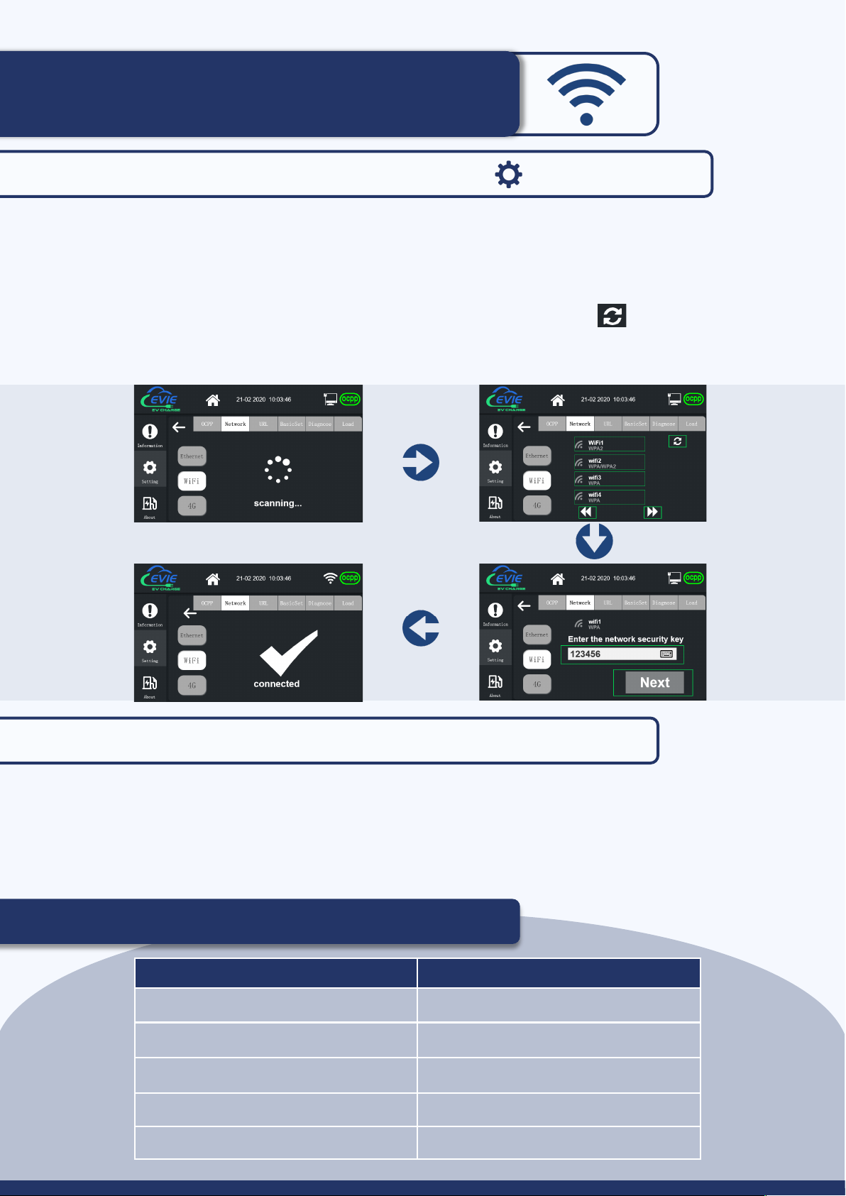
Internet Connection Instructions
• Enter the password (123456) when prompted
• Select ‘Settings’
• Select ‘Network’
• Choose internet connection type (Wifi/Ethernet/Lan/4G)
- Wi-Fi: Press the refresh button to scan for local networks
- Wi-Fi: Enter the network password when prompted
• The OCPP symbol will appear green after successful connection to your internet network
Charging Status Indication
Charger Indicator Function Status
Power = Solid Green Power supply connected
Ready = Flash Green Unit ready to charge
Charge= Solid Green Normal state of charge
Fault = Solid Red Unit fault alarm
Network = Solid green Wi-Fi connected
7
Step 1: Click the settings symbol on the LCD screen
Step 2: Set Date and Time
• Select ‘Settings’
• Select ‘BasicSet’
• Select ‘Time and Date’
• Enter the correct time and date using the keypad
• Click ‘Confirm’
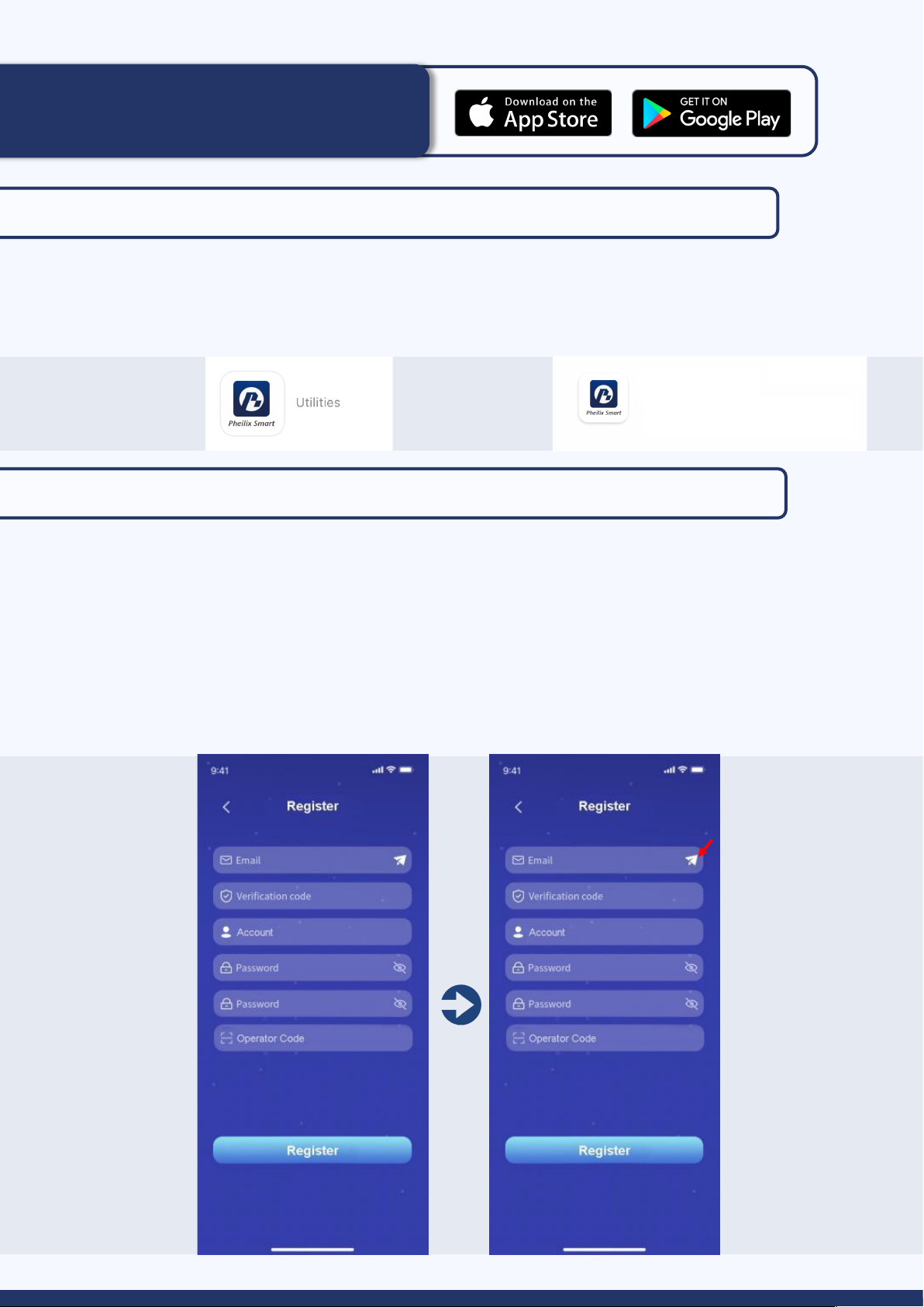
Pheilix App Instructions
Step 1: Download the “Pheilix Smart” app
• Download from the IOS App Store or Google play
• Search “Pheilix Smart” in the stores search bar
• Note: To receive push notifications select enable notifications when prompted or enable
notifications through your phone settings
Step 2: Register your account
• Select Create Account
• Enter your email address
• Press send icon (arrow below, in red)
• A 6 digit verification code will be sent to your email address
• Copy and paste this code into the Pheilix Smart app (shown below)
• Complete the remaining fields in the form, Operator Code is 107.
• Press register
• You will then be granted access to the Pheilix Smart app
8
IOS App Store: Google play:
Pheilix Smart Pheilix Smart

Step 3: Pair your the charger to the Pheilix Smart app
• On the Pheilix Smart App, select ‘Charger’ from the bottom menu.
• Click ‘bind the home device’ symbol (shown below).
• Select the ‘Scan’ symbol (arrow below, in red)
• Scan the QR code on the charger body, click the device once found and this will complete the
paring process.
9
To authorise other users:
• On the Pheilix Smart App select ‘Share’ by pressing the icon within the app
• Input the email address you wish to share the charge point to
• Press Share
• The device will now show in ‘my shared list’

Step 4: Check the Wi-Fi/4G/Ethernet signal
• Ensure the OCPP symbol on the LCD screen is green
• Ensure all indicators are displaying as below:
10
• Secure the gun to your electric vehicle
• Choose “Setting”
• Choose On or OFF for Smart Charging Functions (Default Off-Peak, Random Delay,
DSR)
• Press ‘Start to charge’ to start the charging process
Step 5: Start the charging process
Step 6: Select “Stop Charging” on the Pheilix Smart App to stop the charging
process
Anti-Tamper Alarming
• The Anti-Tamper function consists of a micro-switch which is wired to the
PCB board.
• When the cover is closed, the device will recognise the device as a safe
status.
• When the cover is opened, the micro-switch will activate the signal and
transmit to the PCB. The PCB will transfer a signal to the OCPP platform,
then to the app side to advise the user.

11
RFID Card Charging Process
Operation:
• Connect the charging gun into the unit and the
vehicle
• Press ‘Start’ on the LCD screen
• Tap the RFID card on the unit
• Start charging process
To Bind:
• Tap Account on the app, click ‘My cards’
• Then click ‘Bind User Card’
• Input serial number on the back of the RFID card and press ‘bind user card’. You must
complete this process for each card.
• Once inputted, the card will now show
• Tap Charger on the app, click ‘bind list’ then click each card and press ‘bind user card’
at the bottom of the screen to bind the RFID card
(A user account must be bound to the EVIE unit for the RFID card charging process to work)

12
Error Message: Charging Failure
• The charging gun is not plugged into the car correctly
• Plug the charging gun into the vehicle again
Error Message: Network Failure
• In the event of an error message on the Pheilix app stating the unit is offline OR the
‘Network’ indicator on the unit flashing green reconnect the Wi-Fi:
• Click the settings symbol on the LCD screen
• Enter the password (123456) when prompted
• Click the settings icon
• Select Wi-Fi
• Select the refresh icon shown below
• Select the preferred Wi-Fi network and enter your network password
• The OCPP symbol will appear green after successful connection to your internet network
Emergency Stop Button
• In the event of any electrical failure or emergency press the emergency stop button
• The unit will stop charging
• An error message on the LCD screen will show (As seen below)
• To reset the unit twist the emergency stop button and the LCD screen will return to the
start screen to begin charging again

Need Help?
Please contact Moss Electrical Co. Ltd for any questions or
assistance:
E: sales@eviecharge.co.uk
Technical support: 01322 282 750
W: www.eviecharge.co.uk
13
Moss Electrical Co. Ltd
Maxmor House
Sandpit Road
Dartford
DA1 5BU
Important Safety Instructions
Important Safety Instructions
This manual contains instructions that should be followed during installation, operation and
maintenance of the EVIE Home Charging unit.
For permanently connected (hardwired) charging stations, the unit must be installed by a
qualified electrician and in accordance with the latest 18th edition IET Wiring Regulations.
Please read all instructions before installing and operating the unit. All instruction documents
can also be found online at www.eviecharge.co.uk
When using electrical products, basic precautions should always be taken, including the
following:
• Do not operate the device if there is visible damage to
the unit or charge cord
• Do not put fingers into the charging connector
• Do not install the device near flammable, explosive or
combustible materials
• Do not operate the device in temperatures outside the
operating range (-30°C ~ +55°C)
• Adult supervision is required when using the device
near children
• Do not attempt to repair or service any other part of
the unit yourself
• When the unit is charging do not attempt to remove
the cable from either the unit or the vehicle. Unlock
the vehicle to stop the charging process, allowing you
to remove the cable safety

Solar Panels Generate 1.3MW
of Power On Our Warehouse
Join Moss Electrical
in our goal to become
net zero carbon!
14

15

Moss Electrical (SW) Co. Ltd
01322 282 700
sales@mosselectrical.co.uk
Maxmor House
Sandpit Road
Dartford
DA1 5BU
Moss Electrical Co. Ltd
01656 765 300
sales@mosselectricalsw.co.uk
Horsefair Road
Waterton Industrial Estate
Bridgend, South Wales
CF31 3YN
Moss Electrical (NW) Co. Ltd
0161 848 2468
sales@mosselectricalnw.co.uk
Unit 18 Europa Way
Trafford Park
Manchester
M17 1JZ
Other manuals for EVIECSP732SHA
1
Other EVIE Batteries Charger manuals


