Enelion Vertica User manual

Manual for
ENELION VERTICA Modules,
ENELION VERTICA Pole
and accessories.
Enelion sp. z o.o.
ENELION VERTICA

Copyright, Enelion sp. z o.o.
The manual may change as the product develops.
The information provided may not be correct.
All rights reserved.
Revision: V 6
Number of pages: 48
Released: 17.10.2023
Congratulations on the purchase of the Enelion charger and thank you for your trust.
Before the installation, make sure that the module packages contain all the elements. Current version of the
operation manual can be accessed at: https://enelion.com/en/support/
See the contents of the manual before initiating any activities related to the installation or the activation of the
charger.

10 - 2023
3
Vertica - assembly manual
Contents
1. Important information 5
1.1. General Provisions 5
1.2. Safety instructions 6
2. General information 7
2.1. Additional functions 7
2.2. ENELION VERTICA Pole 7
2.2.1. Opening and closing of the device 7
2.3. ENELION VERTICA Module 9
2.3.1. ENELION VERTICA Module with a socket 9
2.3.2. ENELION VERTICA Module with a cable 9
2.3.3. Assembly and disassembly of ENELION VERTICA Modules 10
3. Design indications of the installation 12
3.1. Electrical Connection Recommendation 12
3.2. Recommended electrical connection 13
3.3. Supplied accessories and electrical connection 13
3.4. Location selection criteria 14
3.4.1. Connection type diagrams 15
3.4.2. Pictorial diagrams of ENELION VERTICA Modules 17
4. Foundation 19
4.1. Enelion prefabricated foundation 19
4.1.1. Construction of the foundation applying the Enelion prefabricated element 19
4.2. Appropriate existing foundation 20
4.2.1. Preparation of the existing foundation 20
4.3. Enelion foundation set 21
4.3.1. Construction of the foundation using the Enelion foundation set 21
5. Installation of ENELION VERTICA Pole 24
5.1. Preparation for installation 24
5.1.1. Standard connection 26
5.1.2. Enelion MID Add-on 26
5.2. Internet connection via Ethernet interface in the LAN 29
5.3. Enelion Chain 30
5.3.1. Add-on – ENELION VERTICA Splitter with an additional meter and residual current protec-

10 - 2023
Vertica - assembly manual
4
tion 34
5.4. Installation of ENELION VERTICA bottom masking panels 36
6. Installation of the ENELION VERTICA Module 37
6.1. Preparation for installation of the ENELION VERTICA Module with socket 37
6.2. Preparation for installation of the ENELION VERTICA Module with a cable 37
6.3. Installation of accessories 38
6.3.1. Enelion Bridge 38
6.3.2. Enelion RCM B 39
6.3.3. Enelion LTE Module 40
6.4. Activation and use 43
7. Maintenance 43
7.1. Cleaning 43
7.2. Repair 43
8. Technical data 44
8.1. ENELION VERTICA Pole 44
8.2. ENELION VERTICA Module with a socket 45
8.3. ENELION VERTICA Module with a cable 46
9. Technical description 47
9.1. Formwithboxestollin 47

10 - 2023
5
Vertica - assembly manual
1.Important information
1.1. General Provisions
The Enelion charger (hereinafter referred to as the
device, charger, or charging terminal) is a charging
station designed for electric vehicle charging within
the meaning of the ‘Act on Electromobility and Alter-
native Fuels’ dated January 11, 2018, in paragraphs 5,
12, 13, and 27 of Article 2 of the aforementioned act.
The installation and servicing of the device must be
carried out by qualied and authorized individuals,
and repairs may only be performed by the manu-
facturer or entities authorized by the manufacturer.
During the warranty period, only authorized service
centers and the manufacturer are allowed to perform
warranty repairs.
Interference with mechanical, electrical, and elec-
tronic components, as well as the device’s software,
is strictly prohibited and may void the warranty.
Exceptions are actions described in the following
instruction manual or those agreed upon in writing
with the manufacturer.
The manufacturer is not responsible for property
damage resulting from prohibited interference with
the product.
The electrical installation to be used during device
operation must meet the conditions described in
the installation manual. The manufacturer is not
responsible for incorrect execution and/or protec-
tion of the electrical installation to which the device
is connected.
The manufacturer is not responsible for the improper
functioning of the electrical installation to which the
device is connected.
The electrical installation to be used during device
operation must comply with the legal standards
applicable at the installation and operation location
of the device.
The manufacturer is not responsible for damages
caused by an electrical installation that does not
comply with legal standards.
The device does not have a built-in power switch.
The device is activated when the power supply volt-
age is applied. Power disconnection must be ensured
by appropriate devices in the electrical installation
described in the installation manual. Except in emer-
gency situations, the device should not be switched
Important information
o during the charging process.
It is prohibited to power on the device when the
device housing is open.
It is prohibited to use a charger that is mechanically
damaged or indicates a critical error.
Objects not intended for this purpose must not be
placed in the charger socket. The only object intended
for insertion into the charger socket is a functional
power cable with the appropriate power and type
for the electric vehicle, terminated with a functional
type 2 plug according to EC 621962.
The use of extension cords, adapters, and charging
cable extensions is prohibited.
The manufacturer is not responsible for loss of health
or life resulting from non-compliance with the above
recommendations.
During the warranty period, the manufacturer allows
the purchase of support packages for the device
(extended warranty/service) subject to a qualifying
review before purchasing the package. Details can
be obtained from the Enelion sales department.
The charging station does not support ventilation
functions.
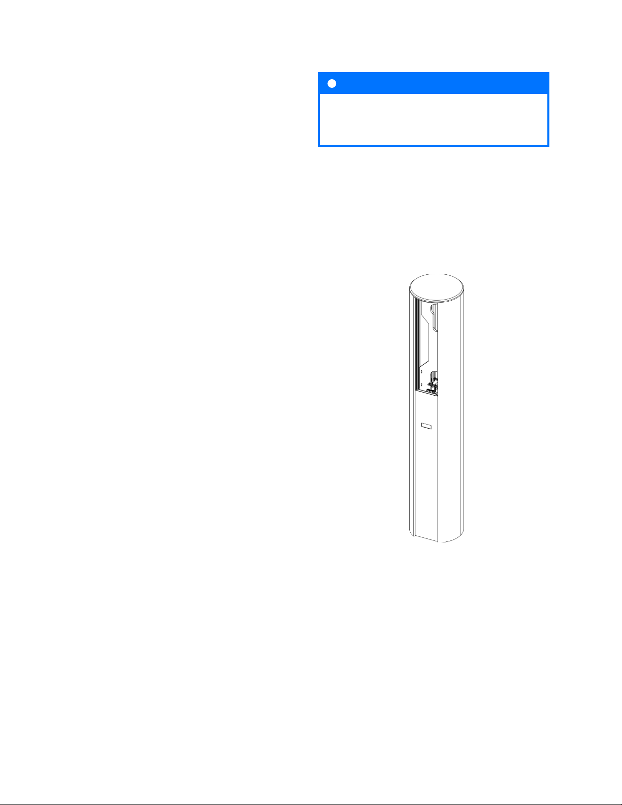
The nameplate present on the device is an integral
part of it and must not be removed or damaged,
as this may result in the loss of the manufacturer’s
warranty.
Fig. 1: Example of info plate
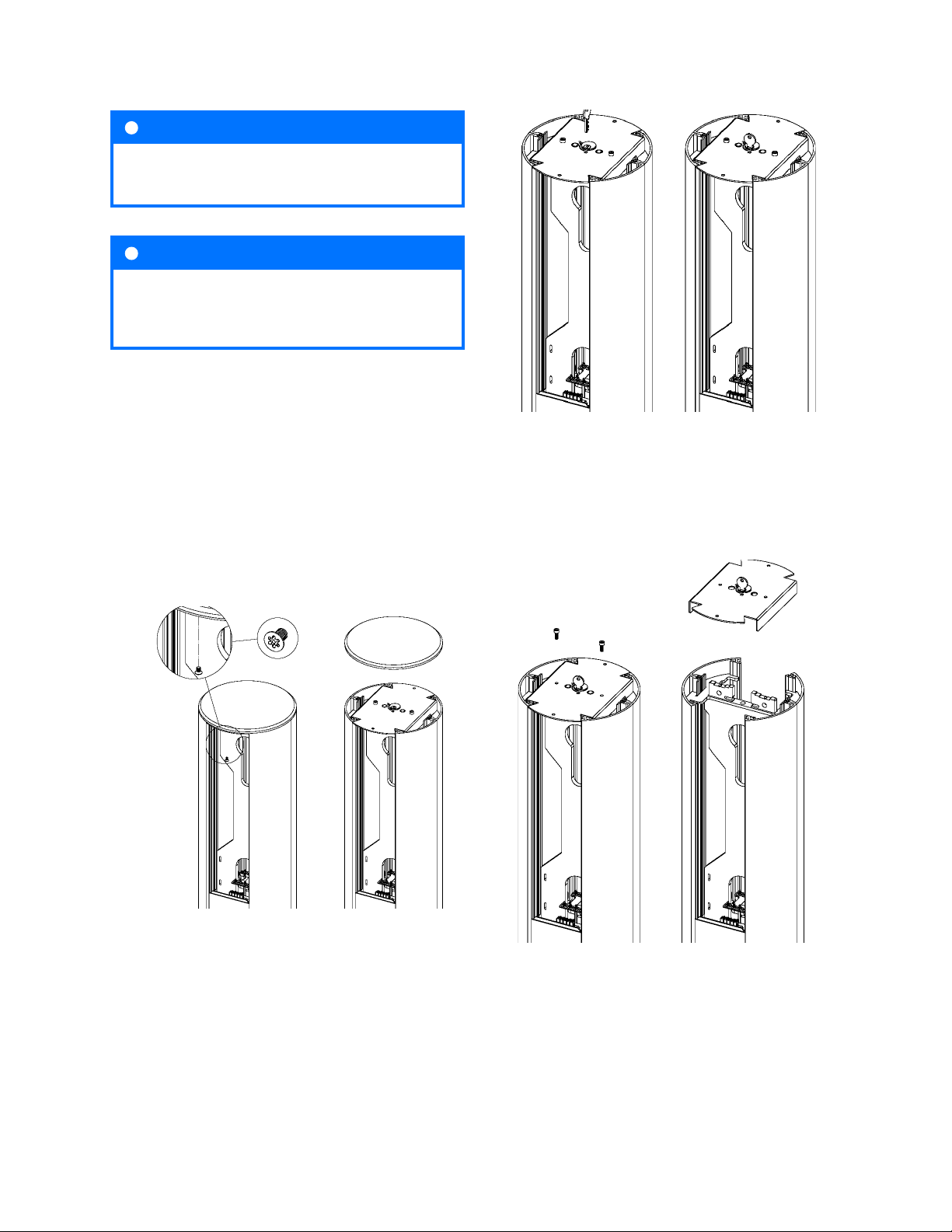
i INFO
Three self-adhesive labels with information
about the current value have been included
in the set. Please select the appropriate one
according to the specications and ax it next
to the nameplate.

10 - 2023
Vertica - assembly manual
6
1.2. Safety instructions
Do not carry out external installation during atmo-
spheric precipitation or strong winds if there is a risk
of water or contaminants entering the device.
All actions described in this manual should be per-
formed after ensuring that there is no voltage in the
power cable.
If any damage to components such as the socket,
charging cable, plug, plug holder, or any other xed/
permanent component is observed, it should be
reported to the charging station operator.
Important information

10 - 2023
7
Vertica - assembly manual
2. General information
ENELION VERTICA is a modular charging station for
electric cars,
which consists of ENELION VERTICA Pole as a casing,
ENELION VERTICA Modules involved in the charging
process and optional addons and accessories.
The modular design facilitates an easy modication
of the functions of the device by replacing or adding
charging modules and accessories to best suit cus-
tomers’ needs. Preparation for use depends on the
selected machine functions of the device.
2.2. ENELION VERTICA Pole
ENELION VERTICA Pole is a necessary part of the
device. ENELION VERTICA Modules are installed in it,
which are the executive part of the charging process.
It is available in 2 colors: silver and black.
General information
i INFO
For more information, please refer to the User
Manual. It contains detailed information about
the functionality and use of the device.
2.1. Additional functions
All Enelion charging stations are compatible with the
original Enelion Chain communication protocol, which
enables operation in the local network of chargers. This
enables the Enelion DLB function to be activated
for dynamic load balancing, reducing the number
of devices that require an Internet connection and
optimizing the use of power in charging vehicles.
All Enelion devices can also be tted with the Enelion
Bridge (an add-on sold separately), which equips the
devices with smart functions and facilitates their
connection to a remote management system (OCPP
1.6 compliant) via the Internet.
Fig. 2: ENELION ENELION VERTICA charging
station.
2.2.1. Opening and closing of the device
ENELION VERTICA Pole structure secures the access
to the interior of the device. Before performing any
operations on the device, open the ENELION VERTICA
Pole according to the instructions.
Fig. 3: ENELION VERTICA Pole without the charging
modules installed.

10 - 2023
Vertica - assembly manual
8
1. Using the Torx Security T25 bit provided, un-
screw the device cover bolts. They are located on
both sides of the device. Put the cover in a safe
place where it will not be exposed to damage.
Fig. 4: Removing the cover of the ENELION VERTICA
Pole.
Fig. 5: Unlocking the lock plate.
Fig. 6: Removing the lock plate.
i INFO
In order to close the ENELION VERTICA Pillar,
perform all steps in reverse order.
i INFO
Closing and opening of the ENELION VERTICA Pole
does not change depending on the presence of
ENELION VERTICA Modules in the device.
2. Unlock the lock plate with the key (if there is a
Yale lock). Next, using the 5 mm Allen key, un-
screw the M6 bolts and remove the lock plate.
3. Dismantle the lock plate by lifting it upwards.
General information

10 - 2023
9
Vertica - assembly manual
Fig. 8: ENELION ENELION VERTICA Module with a
cable.
2.3. ENELION VERTICA Module
2.3.1. ENELION VERTICA Module with a
socket
The ENELION VERTICA Module with a socket is a
functional part of the charging station.
This module provides a Type 2 socket for charging vehi-
cles with up to 32A three phase and can be mounted
on either side of the ENELION VERTICA Pole. It is
equipped with an OLED screen displaying instructions
and information about the charging in progress.
Fig. 7: ENELION ENELION VERTICA Module with a
socket.
2.3.2.ENELION VERTICA Module with a
cable
The ENELION VERTICA Module with a cable is a func-
tional part of the charging station.
The ENELION VERTICA Module with a cable is a func-
tional part of the charging station. This module provides
a charging cable for charging vehicles with up to 32A
three phase and can be mounted on either side of the
ENELION VERTICA Pole. It is equipped with an OLED
screen displaying instructions and information about
the charging in progress.
General information

10 - 2023
Vertica - assembly manual
10 General information
2.3.3. Assembly and disassembly of ENE-
LION VERTICA Modules
i INFO
To shut down the device, perform all steps in
reverse order.
!WARRING
ENELION VERTICA modules equipped with
ENELION VERTICA link are only compatible with
ENELION VERTICA poles that are equipped with
ENELION VERTICA link modules!
ENELION VERTICA modules equipped with
ENELION VERTICAN are only compatible with
ENELION VERTICA poles that are equipped with
ENELION VERTICAN modules!
Fig. 9: ENELION VERTICA pole equipped with
ENELION VERTICA link module
Fig. 10: ENELION VERTICA pole equipped with
ENELION VERTICA link module

10 - 2023
11
Vertica - assembly manual
Fig. 11: ENELION VERTICA module compatible with
a pole equipped with a ENELION VERTICAN module
1. Open the ENELION VERTICA Pole according to
the instructions in section 2.2.1 Opening and clos-
ing of the device.
2. Lift the module above the ENELION VERTICA
Pole and place the bottom edge in the guide slot.
Carefully insert the ENELION VERTICA Module
into the power socket until its top edge is ush
with the edge of the ENELION VERTICA Pole.
3. Close the ENELION VERTICA Pole in accordance
with the instruction 2.2.1 Opening and closing of
the device.
Fig. 12: ENELION VERTICA module compatible
with a pole equipped with a ENELION VERTICA link
module
Fig. 13: Assembly of ENELION VERTICA Modules
General information

10 - 2023
Vertica - assembly manual
12
3. Design indications of the installation
3.1.
Electrical Connection Recommendation
Enelion charging stations are adapted for ve-wire
power supply. In a TN-S 230/400V network, this is
the standard option.
It is possible to power the station from other network
systems described below:
In the case of an IT 120/230 V network, commonly
found in Norway for example, the connection looks as
follows. It’s important to note that one of the phases
serves as the Neutral wire; this is crucial during the
installation of the RCD. In such a network, three-phase
charging is not possible; only some vehicles will be
able to charge using a two-phase system.
In the TN-C system, the PEN wire should be separated
into N and PE, as shown in the diagram below.
Design indications of the installation

10 - 2023
13
Vertica - assembly manual
i INFO
In case of Enelion Splitter, the standard cross
-section of the Cu power cables is 16 mm2.
At the customer’s request, the maximum cross-sec-
tion of Cu/Al power cables is 50 mm2
3.2. Recommended electrical connection
ENELION VERTICA system charging stations are
adapted to a vewire power supply in a TN-S type
network. In the standard type of installation, each
ENELION VERTICA module should be powered by a
separate cable from the switchgear. The switchgear
should have the required protection in the form of an
overcurrent circuit breaker with B or C characteristics
and rated current of 32 A or less, depending on the
conguration of the device. In compliance with the
PN-EN IEC 61851-1: 2019-10 standard, each charging
point must also be individually protected against
residual current type A and B. This requirement can
be met by the administrator/owner when installing a
type B residual current device (RCD B 30 mA/40 A) or
It is not possible to power the station from an IT
230/400 V network.
Other, more complex power supply systems require
technical consultations before purchase.
RCD EV (30 mcA/40 cA) in the switchboard.
The nal selection of the safety devices belongs to an
authorized designer or a qualied electrician.
Another recommended and simultaneously more
economical solution is the installation of an RCD B
purchased from Enelion together with the device. It
is also possible to use the Enelion RCM B – Residual
Current Monitor type B accessory – see section 6.3.2
Enelion RCM B. Enelion RCM B additionally protects
the station and, together with the RCD A used in the
switchgear, meets all safety requirements. If it is neces-
sary to supply the power to the pole with two charging
modules from one cable, ENELION VERTICA Splitter,
described in chapter 5 Installation of ENELION VERTICA
Pole, should be used – the accessory allows for safe
branching of the power supply to two charging panels
inside ENELION VERTICA Pole. Enelion Spliter includes
a junction block, two B32 over current protections, a
wiring set and mounting hardware. The whole device
is mounted on the attached TS35 rails at the bottom
of ENELION VERTICA Pole. Remember to protect each
ENELION VERTICA Module with a residual current
device with the characteristics described above. The
cross-section of the power cables must be selected
by an authorized electrician based on the distance
from the switchgear and other location conditions.
Cables in the ground must be installed in accordance
with the binding building regulations. As a matter of
convenience, exible power cables, stranded type,
terminated with clamping sleeves are recommended
for the installation.
The cable should protrude approximately 80 cm above
the foundation level.
3.3.
Supplied accessories and electrical
connection
Due to the modular structure of the ENELION VERTICA
System charging stations, the method of electrical
connection depends on the applied add-ons. More-
over, in order for certain functions to be performed,
it is necessary to connect the device according to the
determined sequence of phases. Electrical connection
Design indications of the installation

10 - 2023
Vertica - assembly manual
14
of the ENELION VERTICA Pole is typically made with
two separate 5 x 6 mm2Due to the modular structure
of the ENELION VERTICA System charging stations,
the method of electrical connection depends on
the applied add-ons. Moreover, in order for certain
functions to be performed, it is necessary to connect
the device according to the determined sequence of
phases. Electrical connection of the ENELION VERTICA
Pole is typically made with two separate (6 mm2insu-
lated ring terminal, M5 mount). A dedicated crimping
tool for insulated connectors is required. Stranded
cables must be terminated with an insulated crimp
ferrule of the appropriate size.
3.4. Location selection criteria
ENELION VERTICA may be installed both inside or
outside. The device is designed for installation near
parking spaces dedicated to electric vehicles. When
used in the vehicle collision hazard zone, the structure
should be secured with appropriate fenders painted
in yellow and black stripes (warning about the gauge).
i INFO
ENELION VERTICA Pole assembly system en-
ables the pole to rotate by multiple 90-degree
angle turns.
Please bear in mind that the national regulations may
dene the space for the installation. The device should
not be located in a place of high exposure to sunlight,
which could cause its overheating. Do not install the
device near heat sources or in small, closed cubicles
(e.g. in a box).
It is forbidden to install a power cord that does not
comply with the guidelines in section 3.1 Recommended
electrical connection. It is forbidden to install the device
in potentially explosive environment.
Local regulations for electrical installations, re pre-
vention measures and accident prevention must be
taken into account, and escape routes at the installation
site must be provided.
It is forbidden to install the device in a location where
falling objects may damage the charger.
Before installation, make sure that there is free space
above the charger at least one meter from its outline.
Also after installation, make sure that no xed objects
(e.g. advertising boards, road signs, etc.) appear in
the space above the outline of the device. This space
is required for servicing the charging station.
!WARNINIG
The manufacturer accepts no responsibility for
any damage resulting from failure to comply
with the above-mentioned recommendations.
Design indications of the installation

10 - 2023
15
Vertica - assembly manual
Design indications of the installation
3.4.1. Connection type diagrams
Fig. 14: Connection types part 1/2

10 - 2023
Vertica - assembly manual
16 Design indications of the installation
Fig. 15: Connection types part 2/2.

10 - 2023
17
Vertica - assembly manual
Design indications of the installation
Fig. 16: Pictorial diagrams of ENELION VERTICA Modules part 1/2.
3.4.2.Pictorial diagrams of ENELION VERTICA Modules

10 - 2023
Vertica - assembly manual
18 Design indications of the installation
Fig. 17: Pictorial diagrams of ENELION VERTICA Modules part 2/2.

10 - 2023
19
Vertica - assembly manual
4. Foundation
ENELION VERTICA Pole can be installed in three ways:
• on a customized Enelion prefabricated foun-
dation,
• on an appropriate existing foundation with
the use of additional mounting bolts,
• using the Enelion foundation set.
4.1. Enelion prefabricated foundation
The customized Enelion prefabricated foundation
enables shortening the assembly period by eliminating
the need to wait for the concrete to cure.
Fig. 19: Diagram of the foundation excavation.
Fig. 20: Placing the prefabricated element in the
excavation.
The foundation set consists of:
• 1 x prefabricated foundation,
• 8 x washers,
• 8 x M12 nuts.
4.1.1. Construction of the foundation ap-
plying the Enelion prefabricated el-
ement
Fig. 18: Enelion prefabricate foundation.
2. An excavation of over 400 mm x 600 mm (diam-
eter x depth) or 400 mm x 400 mm x 600 mm
(width x length x depth) should be made. Com-
pact the soil directly under the foundation to the
compaction index of at least 0.97.
3. Thread all the required cables through the cable
ducts of the prefabricated foundation. Place the
prefabricated element and plumb it in the trench
at a depth of 0,55 m below the ground level.
1. Remove the M12 nuts and washers from the
prefabricated foundation and secure them until
ENELION VERTICA Pole has been installed.
Foundation

10 - 2023
Vertica - assembly manual
20
Fig. 21: Properly constructed foundation using the
prefabricated element.
Fig. 23: Properly constructed foundation with the
use of anchors.
The foundation prepared in this way enables the
installation of ENELION VERTICA Pole.
After preparing the anchors according to the instruc-
tions, the installation of ENELION VERTICA Pole may
proceed.
4.2. Appropriate existing foundation
In case there is an existing foundation suitable for
the purpose, equipped with an electrical connection,
meeting the legal and construction requirements,
it is possible to install ENELION VERTICA Pole after
ensuring that ENELION VERTICA Pole is properly
attached to the foundation. It is recommended to
apply M12 threaded rods.
1. Drill holes for chemical anchor bolting in the
foundation in accordance with the instructions of
the manufacturer of the applied bolting. Install
the anchors in a square of 120 mm x 120 mm. The
cables must t into the cable grommets of ENE-
LION VERTICA Pole.
4.2.1. Preparation of the existing foundation
Fig. 22: Drilled holes for chemical anchor bolting.
2. Install chemical anchor bolting in accordance
with the instructions of the manufacturer. The
minimum anchorage depth is 110 mm. The in-
stallation should result in the ends of the thread-
ed rods protruding 40 mm to 60 mm above the
foundation surface.
4. Fix the prefabricated element by lling the re-
maining space in the excavation with soil and
compact it to the compaction index of at least
0.97.
Foundation
Other manuals for Vertica
4
This manual suits for next models
1
Table of contents
Other Enelion Batteries Charger manuals

Enelion
Enelion Wallbox User manual

Enelion
Enelion Wallbox Easy User manual

Enelion
Enelion Stilo User manual

Enelion
Enelion Stilo User manual

Enelion
Enelion Vertica User manual

Enelion
Enelion Stilo User manual

Enelion
Enelion Vertica User manual

Enelion
Enelion LUMINA User manual

Enelion
Enelion Vertica User manual

Enelion
Enelion LUMINA User manual