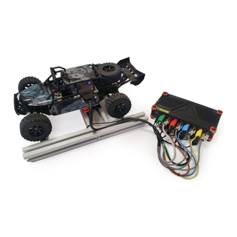
Evil Mad Scientist 2575 User manual

1
Brushless Servo Upgrade Kit
— Installation Guide —
Models 2575, 2576, 2577, 2578
Email: con[email protected]
Tech support chat: axidraw.com/chat
If you should need any assistance installing this upgrade,
please let us know right away; we’re here to help!
There are variations between dierent AxiDraw
machines. If something doesn’t look right or doesn’t
seem to fit right, please don’t hesitate to say so.
Please let us help you get up and running!
This upgrade kit, compatible with most AxiDraw V3
and AxiDraw SE family machines, replaces the stan-
dard pen-lift servo motor with a narrow-band brush-
less servo motor and upgrades the AxiDraw power
supply.
This guide walks through the process of installing the
new motor, including replacing the servo mount and
mounting and connecting the new electronics.
We strongly recommend that you read through all
of the steps before starting the installation. One key
reason is to make sure that you have the correct tools
needed for your specific upgrade configuration.
For ease of viewing the photos in this guide, consider
reading this guide on a phone, tablet, or computer
screen, rather than printing it.
Rev A; 2023-01-27
Preliminary step 1: Tool check
Certain tools are required to install this upgrade; they are not included with this upgrade kit:
• Wire cutters, sharp scissors, or a similar tool to cut cable ties.
• Hex L-wrenches: 2 mm and 2.5 mm
(Both hex L-wrenches are included in the standard set of tools that ships with an AxiDraw.)
• One specialized screwdriver; type to be determined.
That screwdriver will be type PZ1, PZ2, or T20, depending on your AxiDraw. To determine which, for
your exact configuration, keep reading.
You may also find tweezers and a pin, needle, or ballpoint pen tip helpful.

2
Preliminary step 3: Compatibility Checks & Starting Point
To verify that your AxiDraw is ready for this upgrade, look at the mounting bracket where your existing
pen-lift servo motor is attached. Compare its appearance to the two photos below:
Preliminary step 2: Disconnect the AxiDraw
Before anything else, physically disconnect both the USB and power cords from the AxiDraw.
(B) If the mounting bracket looks like the photo
above, with a silver-colored aluminum flap that
covers the top of the servo motor:
The installation process will involve removing the
old (silver-colored) servo mount and replacing
it with the upgraded black one. Make sure that
you have upgrade kit model 2575 or 2576, which
come with the black mount included. (If you
don’t, please contact support to get that part.)
If your AxiDraw looks like this, skip directly to
Part B, starting with Step B1, starting on page
8.
If your servo mounting bracket is not of this shape — if it does not have the metal
flap above the servo motor — your AxiDraw is probably not directly compatible with
this upgrade. (Please contact support to discuss upgrade options for your AxiDraw.)
(A) If the mounting bracket looks like the photo
above, with a black-colored aluminum flap that
covers the top of the servo motor:
The installation process will involve removing the
old servo motor (without removing or replacing
the servo mount).
If your AxiDraw looks like this, proceed to Part A,
starting with Step A1 on the next page.

3
Step A1: Screwdriver needed
The screwdriver that you will need is a Pozidriv PZ1, or
“Pozi #1”. Make sure that you have one on hand before
proceeding.
Part A - Swapping the servo motor
Part B is for AxiDraw units that already had the black servo mount to begin with. If you just installed a servo
mount in Part A, instead skip ahead directly to Part C.
Fig 1
Fig 2
Step A2: Disconnect old servo
The existing servo wiring is typically held in place by
two cable ties, as indicated (Fig 1).
Use wire clippers or sharp scissors to cut and re-
move both cable ties. Do not cut or damage the
wiring itself.
Once the cable ties are cut, disconnect the old ser-
vo motor by pulling its cable end (brown/red/yellow)
out of the jack as shown (Fig 2).
Step A3: Detach the old servo
Using your PZ1 screwdriver, unscrew the two screws
that hold the old servo motor in place and thus re-
move it from the servo mount (Figs 3-4).
Fig 3 Fig 4

4
If your servo mounting bracket looks like the
photo above, with only 1 hole through the cable
guide, you will disconnect the cable guide.
To do so, proceed on to Step A5 on the next
page.
If your servo mounting bracket looks like the pho-
to above, with 3 holes through the cable guide,
you will leave the cable guide attached.
Thus, skip ahead to Step A6 on page 6.
Step A4: Check the cable guide
Take a close look at where the cable guide is attached to the servo mount, and compare it to the pictures
below:
3 Holes 1 Hole

5
Cable guide
backer
Rivets
Fig 2
Fig 1
Step A5: Remove the cable guide
If you have 3 holes visible through the cable guide — from
step A4 — skip this step; leave your cable guide attached.
The cable guide — the flexible black plastic ribbon — is
attached to the servo mount by two plastic rivets (Fig
1). (The exact shape of your cable guide may not match
the one shown here; they vary slightly between Axi-
Draw models.)
Between the cable guide and the servo mount is a sec-
ond piece of black plastic, the cable guide backer, also
held in place by those rivets.
Remove the two plastic rivets, to release the cable
guide parts from the servo mount.
The best way to remove this type of rivet is to press the
center pin in from the back side (Fig 2), with a narrow
implement like a pin, needle, screwdriver, or sturdy pen
point. Once you push that center point in a bit, you can
pull out the two parts of the rivet from the front side.
Once both rivets are removed, carefully separate the
parts (Fig 3).
Fig 3
Cable guide backer
Cable
guide

6
Step A6: Identify servo motor and screws
First, identify the brushless servo motor and the four
small screws from the kit of upgrade parts (Fig 1).
Orient the black lift arm of the servo motor pointing
towards the cable, as shown here.
Aside: If the servo motor in your upgrade kit is al-
ready attached to a mount (Fig 2), use the PZ1 driver
to remove the four screws that hold it in place, get-
ting you back to the state shown in (Fig 1).
Step A7: Attach the brushless servo motor
Test fit the new servo motor in place, behind the servo
mount. Lift up the front face of the vertical slide so that
it can rest on the wheel at the end of the black lift arm
(Fig 3).
(If the vertical slide has come “unfolded”, with the two
parts “hinged” together, fold it back together so that
the rails slide vertically.)
Then, use your PZ1 driver to attach the new servo (Fig
4) in place with the four screws. The screws go through
the four holes at the corners of the motor and into the
matching (outer four) holes of the servo mount.
Get all four screws started before tightening any of
them, and then tighten each with gentle pressure (Fig
5).
Fig 1
Fig 2
Fig 4 Fig 5
Fig 3

7
Step A8: Add the warning label
Locate the “Warning” label from the kit of upgrade
parts (Fig 1).
Peel the label o of the backing. (The label may have a
large black outer rectangle left over from the printing
process; we only need the smaller inner label part.)
Place the label on the top of the metal flap at the top of
the servo mount (Fig 2), taking care to fit it on the met-
al part, and not covering either of the holes in the top
of the servo mount. You may find tweezers or a similar
tool helpful.
Then, smooth the sticker into place (Fig 3).
Fig 1
This concludes Part A.
Next, skip directly ahead to Part C, starting on page 13.
Fig 2
Fig 3

8
Step B1: Tool check
To determine the screwdriver type that you’ll need,
remove the pen clip and lower your pen position to its
lowest point (Fig 1). Look through the hole in the front
face of the pen slide to see the two screw heads visible
inside. You may need to manually lift the pen slide up a
bit in order to see them.
If the two screw heads have a 6-pointed star shape, the
necessary screwdriver is a Torx T20.
If the two screw heads have a cross shape, the neces-
sary screwdriver is a Pozidriv PZ2, or “Pozi #2”.
Part B - Upgrading the servo mount
Part B walks through the first steps for upgrading from
an AxiDraw with a silver-colored servo mount. If you just
finished Part A, skip past this section, directly to Part C.
Step B2: Remove the vertical slide
Disconnect the AxiDraw from power and USB.
Then, using the appropriate screwdriver, loosen and
remove those two screws (Fig 2). They will be tight.
Be extremely careful as you remove the screws: Alter-
nate between them as you unscrew them, and make
sure that the screw heads are free of and do not press
against the vertical slide; they could damage the slide.
These two screws normally attach the vertical slide to
the Y-carriage of the AxiDraw, clamping the old servo
mount in place between them. The old servo mount is
still attached to the cable guide.
Once it is loose, take care because the front edges of
the Y-carriage may be sharp.
In the steps that follow in Part A, we will detach the
cable guide, and then attach the vertical slide with the
new servo mount.
Fig 1
Torx
T20
Pozidriv
PZ2
Fig 2
Screws
Vertical slide
Old servo
mount
Y-carriage
Cable guide

9
Step B3: Disconnect the old servo
The existing servo wiring is typically held in place by
two cable ties, as indicated (Fig 1).
Use wire clippers or sharp scissors to cut and re-
move both cable ties (Fig 2). Do not cut or damage
the wiring itself.
Once the cable ties are cut, disconnect the old ser-
vo motor by pulling its cable end (brown/red/yellow)
out of the jack as shown (Fig 3).
Fig 1
Fig 2
Fig 3

10
Step B4: Disconnect the cable guide
The cable guide — the flexible black plastic ribbon
— is attached to the old servo mount by two plastic
rivets (A). (The exact shape of your cable guide may
not match the one shown here; they vary slightly
between AxiDraw models.)
Between the cable guide and the servo mount is a
second piece of black plastic, the cable guide back-
er, also held in place by those rivets.
Remove the two plastic rivets, to release the cable
guide parts from the old servo mount.
The best way to remove this type of rivet is to press
the center pin in from the back side (Fig 2), with a
narrow implement like a pin, needle, screwdriver, or
sturdy pen point. Once you push that center point
in a bit, you can pull out the two parts of the rivet
from the front side.
Once both rivets are removed, carefully separate
the parts (Fig 3). This concludes removing the old
servo mount. In the next step, we begin installing
the new servo mount.
Cable guide backer
Old servo
mount
Rivets
Fig 2
Fig 1
Fig 3
Cable guide
backer
Cable
guide

11
Step B5: Attach the new servo mount
Now, let’s attach the vertical slide with the new
servo mount.
First, get things oriented correctly:
1. Rotate the black lift arm on the servo to point
down to the right, as shown here (Fig 1).
2. If the vertical slide has come “unfolded”, with
the two parts “hinged” together, fold it back
together so that the rails slide vertically.
3. Orient the vertical slide as shown here, with
only a single shaft coming out the top.
Then, drop the two screws from the vertical slide
through the big hole in the front of the vertical
slide, into their slots (Fig 1).
Next, place the servo mount behind the vertical
slide (Fig 2), such that:
1. The black lift arm is still pointing down, now
hidden by the vertical slide,
2. The vertical slide is still oriented with the one
shaft coming out the top.
3. The two screws go through the two big slots
in the black servo mount.
Finally, use those two screws to re-attach the slide
assembly to the end of the Y carriage (Fig 3).
The front face of the Y carriage may have two or
four holes in it.
• If there are only two holes, use those.
• Otherwise, for all AxiDraw models except the
AxiDraw V3/A3, use the top two holes.
• On the AxiDraw V3/A3 only, use the bottom
two holes (which are further apart).
Be extremely careful as you screw this back into
place. Alternate between two screws and make sure
that both screw heads are kept free of and do not
press against the vertical slide; they could damage
the slide.
Fig 1
Fig 2
Fig 3
Rotate arm
down

12
Step B6: Checks
Your new servo mount and coreless servo should
now be installed in place behind the vertical slide
(Fig 1).
Basic checks to make sure that everything looks OK:
• The vertical slide should move up and down
freely when you lift it.
• The vertical slide should be supported by the
rolling wheel at the end of the lift arm.
• The vertical slide and servo mount should be
reasonably perpendicular to the table top, not
at an odd angle.
If anything is amiss, this is a good time to identify
and correct it.
Step B7: Special check on AxiDraw V3/A3
For AxiDraw V3/A3 only: there is one more check.
Slide the Y carriage all the way back to the main car-
riage. The new servo mount should not contact the
cover over the main carriage. There is normally very
little clearance here (Fig 2), but it should not ac-
tually catch there, limiting travel or causing excess
friction.
If it does contact, then very slightly loosen the two
screws that hold the vertical slide in place, and pull
the servo mount up as far as it will go while you
tighten the two screws again.
Fig 1
Fig 2
This concludes Part B.
Next, proceed to Part C, starting on the next page.

13
Part C - Cable Guide & Tiedown
Step C1: Attach the cable guide
If your cable guide is already attached — if you left it
on as directed by an earlier section — skip this step and
proceed to Step C2 on the next page.
First, locate the parts for attaching the cable guide.
In addition to the existing cable guide (still attached
to the AxiDraw) you’ll need the cable guide backer
that you removed earlier, plus two long plastic rivets
and a black plastic spacer (Fig 1) from the upgrade
kit.
Place the spacer in position first, aligning its two
large holes over those in the servo mount (Fig 2),
and the small holes over the protruding screws that
mounted the servo motor.
Next, align the cable guide backer behind the end
of the cable guide. Slip one of the plastic rivets
through one of the two large aligned holes in the
pair (first through the cable guide and then through
the backer). Then, guide the point of the rivet
through the matching hole of the spacer and servo
mount. If everything looks aligned, press firmly to
snap the rivet into place (Fig 3).
Then, press the other rivet through the remaining
hole and snap it into place as well (Fig 4).
Fig 1
Fig 2
Spacer
Long rivets
Cable guide
Cable guide
backer
Fig 3 Fig 4
Cable guide Cable guide
backer

14
Step C2: Connect the servo cable
Plug the new servo motor into the connector jack
until it is fully seated (Fig 1). As you do so, take care
to avoid any extra twisting of the cable; It’s best if it
lays flat to the extent possible.
The orientation matters; connect the cables with
the expected orientation (Fig 2):
• Black to Black
• Red to Red
• White to White
Fig 1
Fig 2

15
Step C3: Begin tying down the cable
We now begin the process of tying down the excess
cable slack.
Ideally, we would like to end up with something as
neat as the first pictures of this upgrade guide, be-
fore removing the old servo motor. We should end
up with the red-white-black cable strain relieved in
the same place — under the metal tab — and tied
down neatly on the other side.
In practice, the amount of available cable slack
varies from unit to unit, and it is not always easy or
straightforward to achieve such a clean result. The
important thing is that you don’t leave extra cable
loops hanging down that can get caught on some-
thing as the AxiDraw moves.
In case of ambiguity or variation, prioritize tying
the cables up in a way that prevents hanging cable
loops. (And, ask for help if you need it).
To get started: Tuck the black/red/white cable under
the metal tab of the servo mount, and insert a cable
tie down through the hole in the tab (Fig 1). Loop
the cable tie back up and through the end clasp
(ferrule) of the cable tie (Fig 2). Don’t cinch it tight
just yet.
Fig 1
Fig 2

16
Step C4: Finish tying down the cable
Tuck the excess cable over the top of the servo mo-
tor and below or behind the metal flap above it.
If you have enough slack to do so, add a second ca-
ble tie on the opposite side, down through the hole
capturing this part of the cable in place (Fig 1).
If everything looks neat — or neat enough; without
loops of cable hanging down — go ahead and cinch
up the two cable ties and trim o any excess ends of
the cable ties (Fig 2).
As an alternative, if there isn’t as much cable slack
available, you can put the second cable tie beneath
the metal flap that covers the top of the servo mo-
tor (Fig 3). If you do so, try to arrange things such
that the cable ties don’t cover the warning label (Fig
4). Cinch the two cable ties tight and cut the excess
ends.
Fig 2
Fig 4Fig 3
Fig 1

17
Step C5: Checks
The final appearance may vary a bit, but the im-
portant thing is that there should not be any excess
cable below the servo motor itself (Fig 1). The cable
should be tied down well enough that it can’t fall
down below that point either.
Finally, before we move along, make sure that the
front face of the vertical slide is supported by the
little white rolling wheel at the end of the pen lift
arm (Fig 2).
Keep clear below line
Fig 1
Fig 2
This concludes Part C (Cable Guide & Tiedown)
Next, proceed to Part D, starting on the next page.

18
Part D - Upgrading the electronics
Step D1: Disconnect servo cable
On the left-hand side of the AxiDraw, disconnect
the servo extension cable, the black-red-white ca-
ble. Pull it straight out to release it (Fig 1).
Step D2: Remove three cover screws
Identify the three highlighted screws on the top of
the black metal cover over the AxiDraw electronics
(Fig 2).
There are four screws on the top of the cover. The
three to remove are the two “front” screws, clos-
est to the Home label, plus the one in the back left,
closest to where you disconnected the servo cable.
Using one of the hex L-wrenches, unscrew and re-
move those three screws (Fig 3, Fig 4).
Depending on the age and model of the AxiDraw,
you’ll either use the 2 mm or the 2.5 mm hex
L-wrench, to remove the screws (which are either
M3 or M4 size).
Keep track of which size hex L-wrench you used;
that will be helpful shortly.
Fig 1
Fig 2
Fig 3 Fig 4

19
Step D3: Stage the power module
Identify the power module (Fig 1) from the upgrade
kit.
The power module has a channel through its lower
side, designed for routing cables.
Place the power module over the old electronics
cover, roughly lining up the three holes in it with the
holes from the three screw holes that you removed
(Fig 4).
Fig 1
Fig 2
Fig 3 Fig 4
USB Power
Optional but highly recommended:
Place the power module over your USB and pow-
er cables, with the two cables fitted into its lower
channel as shown (Fig 3).
The two cable ends should come out the front of
the channel: The small (“micro-B”) end of your
USB cable and the barrel plug from the new 2.5 A
power supply included with the upgrade kit.
(Do not plug in either end of either cable yet.)

20
Step D4: Lightly attach power module
The upgrade kit includes 6 long black screws: 3
each, in two dierent thread sizes (M3, M4). You’ll
need 3 of one size or the other.
Find the 3 screws that are the same type as the
short ones that you removed. If you kept track of
which hex L-wrench you used to remove them, use
the screws that fit that same wrench. Otherwise,
compare the screw diameters.
Place the screws through the three holes in the top
of the power module. Thread them very lightly into
place: One turn only, to hold them in place (Fig 1).
Step D5: Connect the new servo wiring
One of the two cables coming out of the power
module has only two wires on it, black and white.
Connect that cable to the EBB control board, in the
third position up (two positions above where the
old servo cable was connected), with the black wire
towards the back of the AxiDraw and white towards
the front (Fig 2, Fig 3).
Then, connect the two remaining cable ends togeth-
er: the old servo plug goes into the new three-wire
cable from the power module (Fig 4). Red to red,
black to black, white to white (or white to blue, on
the AxiDraw SE/A1 and SE/A2).
Fig 1
Fig 2
One turn
Fig 3
Fig 4
This manual suits for next models
3
Table of contents
Other Evil Mad Scientist Science Education Product manuals


