Evil Mad Scientist AxiDraw MiniKit 2 User manual
Assembly Guide
Model 2542
https://emsl.us/924
AxiDraw
MiniKit 2
AxiDraw MiniKit 2 Assembly guide v 2.5
Last updated: May 8, 2021

Table of Contents .............................................2
Introduction ......................................................4
About this guide and this kit........................ 4
Getting help................................................... 4
Software......................................................... 4
Warning: Small parts..................................... 4
Warning: Sharp edges and points ............... 4
After assembly .............................................. 4
More about AxiDraw and MiniKit ............... 4
Part 1: Tools .......................................................5
1.1 Required tools .......................................... 6
1.2 Included tools .......................................... 7
Part 2: The Base ................................................8
2.1 Parts in the base assembly..................... 9
2.2 Ballast Weight ......................................... 10
2.3 Add pulleys to motors ........................... 12
2.4 Install the motors................................... 14
2.5 X Endstops............................................... 16
2.6 Mounting the EBB.................................. 17
Part 3: The X Carriage......................................20
3.1 Parts in the X Carriage Assembly.......... 21
3.2 Install the Y Endstop .............................. 22
3.3 Spacers, shims, and washers ................. 23
3.4 X Carriage Idler Pulleys ......................... 24
3.5 Y Wheel Supports................................... 25
3.6 Preset Y Eccentrics................................ 28
3.7 Front X Wheels........................................ 29
3.8 Rear X Wheels......................................... 31
3.9 Tuning the X Carriage ............................ 33
Part 4: Y, Belt, and Z.........................................35
4.1 Parts in the Y, Belt, and Z assemblies ... 36
4.2 Tensioning block..................................... 37
4.3 Y Carriage Idler Pulley........................... 38
4.4 Y Carriage Travel Limits......................... 39
4.5 Y Endcap and Pre-threading................. 40
4.6 Fixed Y Wheels ....................................... 41
4.7 Aside: AxiDraw kinematics.................... 42
4.8 Belt Staging ............................................ 43
4.9 Add the Y Carriage ................................ 45
4.10 Belt tensioning...................................... 46
4.11 Trim the belt ends.................................. 50
4.12 Tuning the Y Carriage........................... 51
4.13 Adding the Z Slide................................. 53
Part 5: Servo and wiring...................................55
Table of Contents
2

5.1 Parts used in Servo and Wiring.............. 56
5.2 Stepper wiring 1 ...................................... 57
5.3 Stepper wiring 2 ..................................... 58
5.4 Cable guide wrapping............................ 59
5.5 Mounting the servo................................ 61
5.6 Mount the cable guide .......................... 62
5.7 Complete the wiring .............................. 64
5.8 Servo horn............................................... 68
5.9 Servo calibration .................................... 69
Part 6: Using AxiDraw MiniKit ........................72
6.1 Accessories ............................................. 73
6.2 The AxiDraw User Guide ...................... 74
6.3 Special considerations for MiniKit ....... 74
6.3.1 Pause button.................................................74
6.3.2 Home corner ...............................................74
6.3.3 Travel limits ..................................................75
6.3.4 Pen weight ...................................................75
6.3.4 Rubber bands...............................................75
6.3.5 Speed and acceleration..............................75
Additional Resources .......................................75
3

Introduction
About this guide and this kit
This is the assembly guide for AxiDraw MiniKit 2, a com-
pact “DIY kit” version of the AxiDraw writing and drawing
machine.
This guide covers steps needed to build the MiniKit 2, from
opening the box to a working machine. It also covers mod-
el-specific usage information about the MiniKit, as a sup-
plement to the main AxiDraw User Guide.
This guide is provided as a PDF download, with the intent
that it can be viewed on-screen (desktop, laptop, tablet or
phone) while you assemble your kit. The latest version is
available at: wiki.evilmadscientist.com/minikit
Note: These instructions do not cover the previous genera-
tion AxiDraw MiniKit – without the 2 – model 2540. If you
have that model, see the separate assembly instructions
for it, available at the same link.
Getting help
If you should need any kind of assistance while building
your AxiDraw MiniKit, please do not hesitate to contact
us: shop.evilmadscientist.com/contact
Whether you need help with an assembly step, parts sup-
port, assistance troubleshooting an issue, or reassurance
that you’re building something correctly, please feel wel-
come to drop us a line. We are here to help.
Software
Towards the end of this guide, you will need AxiDraw soft-
ware on your computer. Get started at: axidraw.com/sw
Warning: Small parts
This kit is not a toy. It contains a great number of small
parts that should be kept out of reach of children.
Warning: Sharp edges and points
While the finished kit should not present any excessively
sharp edges, some components within this kit may have
edges and points that are razor sharp. Exercise appropriate
care when handling, and keep away from children.
After assembly
After assembling your AxiDraw MiniKit, you will want to
review the usage information in the AxiDraw user guide,
available at: axidraw.com/guide
More about AxiDraw and MiniKit
To learn more about AxiDraw in general please visit its main
site: AxiDraw.com
To learn more about the AxiDraw MiniKit, please visit its
product page: emsl.us/924
The main documentation site for AxiDraw can be found on
our wiki, at axidraw.com/docs 4

Part 1: Tools 5
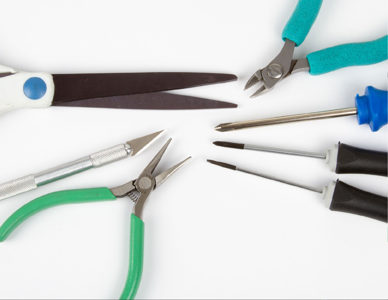
1.1 Required tools
To assemble the AxiDraw MiniKit, you will need certain
general-purpose tools that are not included with the kit.
These required tools are:
1. Either Ascissors or Bwire clippers
2. A Phillips #1 size screwdriver, C
3. A Phillips #0 size screwdriver, D
4. A small flat head screwdriver, E
Blade width: about 2 mm or 5/64”
And, recommended but not required:
• Miniature pliers, F
• A small hobby knife, G
• A small adjustable wrench (not shown)
A
B
C
D
E
F
G
6

1.2 Included tools
Several specific tools are included with the kit.
We will refer to these, and other parts included with the kit, by part numbers.
The included tools are:
#1, 15 cm / 6 inch Ruler
#2, T20-size Torx L-wrench
#3, 2 mm Ball-end Hex L-wrench
#4, 2.5 mm Hex L-wrench
#5, 10 mm Low-profile Wrench
#6, 8 mm Low-profile Wrench
#7, 7 mm Low-profile Wrench
The three L-wrenches re distinctive. Only #2 is Torx (str-shped) wrench. And the only
one with bll end is the 2 mm L-wrench, #3. However, the three Low-profile Wrenches re
very similr in ppernce; you my wnt to lbel them with mrker.
Most of the wrenches re only needed during ssembly. However #3, the bll-end wrench,
will continue to be useful in regulr everydy opertion of the MiniKit fter ssembly.
#1
#2
#3
#4
#5
#6
#7
7

Part 2: The Base 8

#8, MiniKit Base Rail (1)
#9, Ballast Weight (1)
#10, Nylon Loop Clamp (2)
#11, M4×20 Torx Tapping Screw (2)
#12, Motor Wire Harness, Long (1)
#13, Stepper Motor (2)
#14, Timing Belt Pulley (2)
2.1 Parts in the base assembly
#9
#10
#20 #21
#22
#23 #24
#8
#11
#12
#13
#14
#15
#16
#17
#18
#19
#15, M3×14 Button-head Screw (8)
#16, X Endstop (2)
#17, M4×12 Torx Tapping Screw (4*)
#18, EBB Driver Board (1)
#19, EBB Support (1)
#20, M3×16 Button-head Screw (4)
#21, White Nylon Washer (4)
#22, Black Nylon Spacer (4)
#23, M3 Kep Nut (4)
#24, M4×8 Torx Tapping Screw (4*)
*Note: Some of the screws counted here
will not be used until a later step.
9

2.2 Ballast Weight
1. Identify the Base Rail #8, the Ballast Weight #9, the two nylon loop clamps
#10, and the M4×20 Torx tapping screws. These screws can be identified by
the star-shaped socket on their heads and length of approximately 20 mm,
as measured below the head (A).
2. Press the screws through the loop clamps as shown (B).
3. Check the ballast weight for any sharp edges, and dull them if necessary
using (for example) the side of a screwdriver blade (C). (The ends may be
sharp as well, but they are mostly protected once installed.)
4. Orient the Base Rail as shown: With the two “middle” holes shown on the
side facing up and towards you (D). These are the two holes that line up with
those on the Ballast Weight.
!The ballast weight may have sharp edges;
Handle with appropriate care.
#10 #11
C
B
A
(Continues on next page)
D
Note: These are tapping screws, designed to create strong
threads in drilled holes that are not initially threaded.
10

5. Place the Ballast Weight on top of the Base Rail, lining up the
two pairs of holes, and insert the tips of the screws through
the two pairs of holes. Orient both loop clamps so that they
point “straight out” away from the Rail (E).
6. Turn the screws into place with #2, the Torx L-wrench (F). Al-
ternate between the two screws until both are tight.
7. Slip the Long Motor Wire Harness #12, through both loop
clamps in the direction shown (G). With the loop clamps point-
ing towards you, the connector should end up on the RIGHT
end of the Base Rail.
F
E
Tip: You may find it easiest to start the screws on the
“long” end of the wrench and then tighten them with the
short end (shown).
G
§2.2 Ballast Weight, continued
11
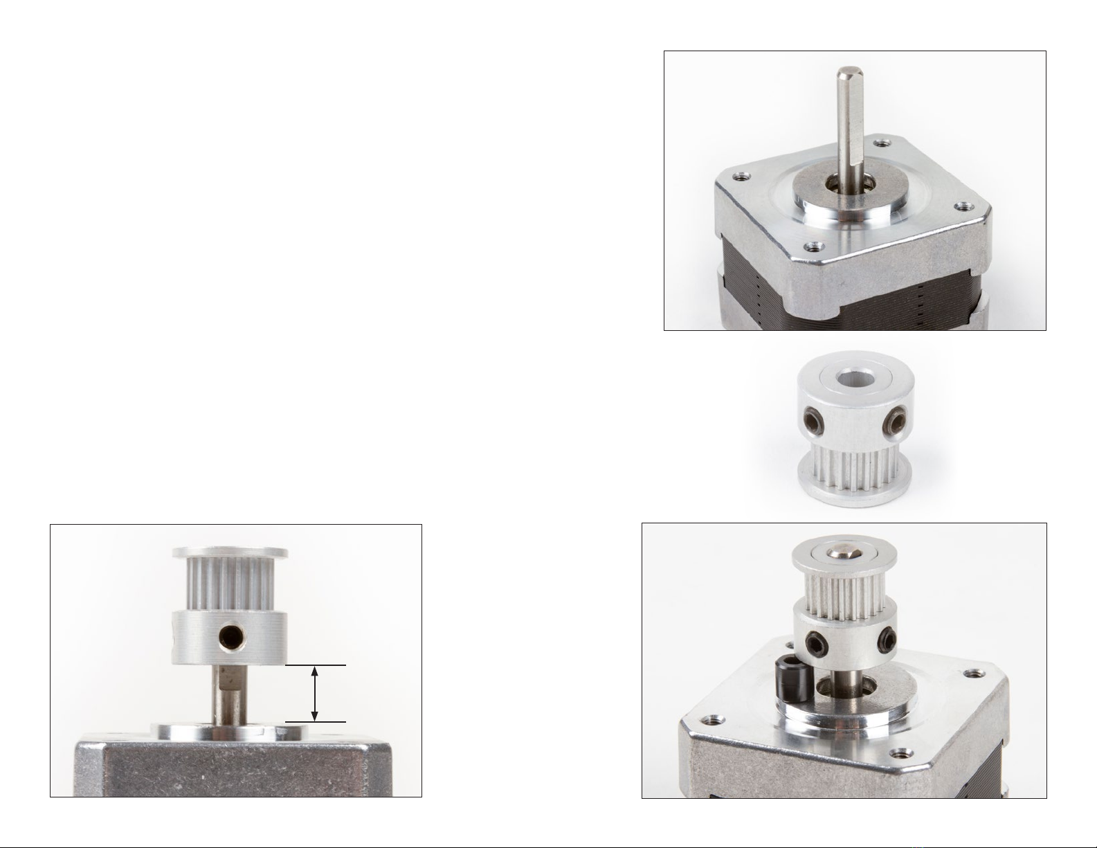
6 mm
2.3 Add pulleys to motors
1. Locate the flat face (A) on the shafts of the stepper motors, #13.
2. Observe that the timing belt pulleys, part #14, each have two set
screws (B). The wrench for these screws is the 2 mm Ball-end Hex
L-wrench #3.
3. Slide a pulley onto a motor shaft, “teeth” up. You may need to
loosen the set screws to do so.
4. Position the pulley with a set screw in front of the flat face, and
with its bottom 6 mm above the uppermost part of the motor face
(C). You can use a ruler to measure the gap or – much better – bor-
row a Black Nylon Spacer (#22) from a future step and use it as a
spacer to measure the gap (D).
A
CD
B
(Continues on next page)
12

E
F
5. Firmly tighten the set screw against the flat face of the motor shaft, using
the short end of the hex wrench (E).
6. Tighten the second set screw on the pulley, again using the short end of the
hex wrench.
7. Use the same method to add the second pulley to the second motor (F).
§2.3 Add pulleys to motors, continued
13

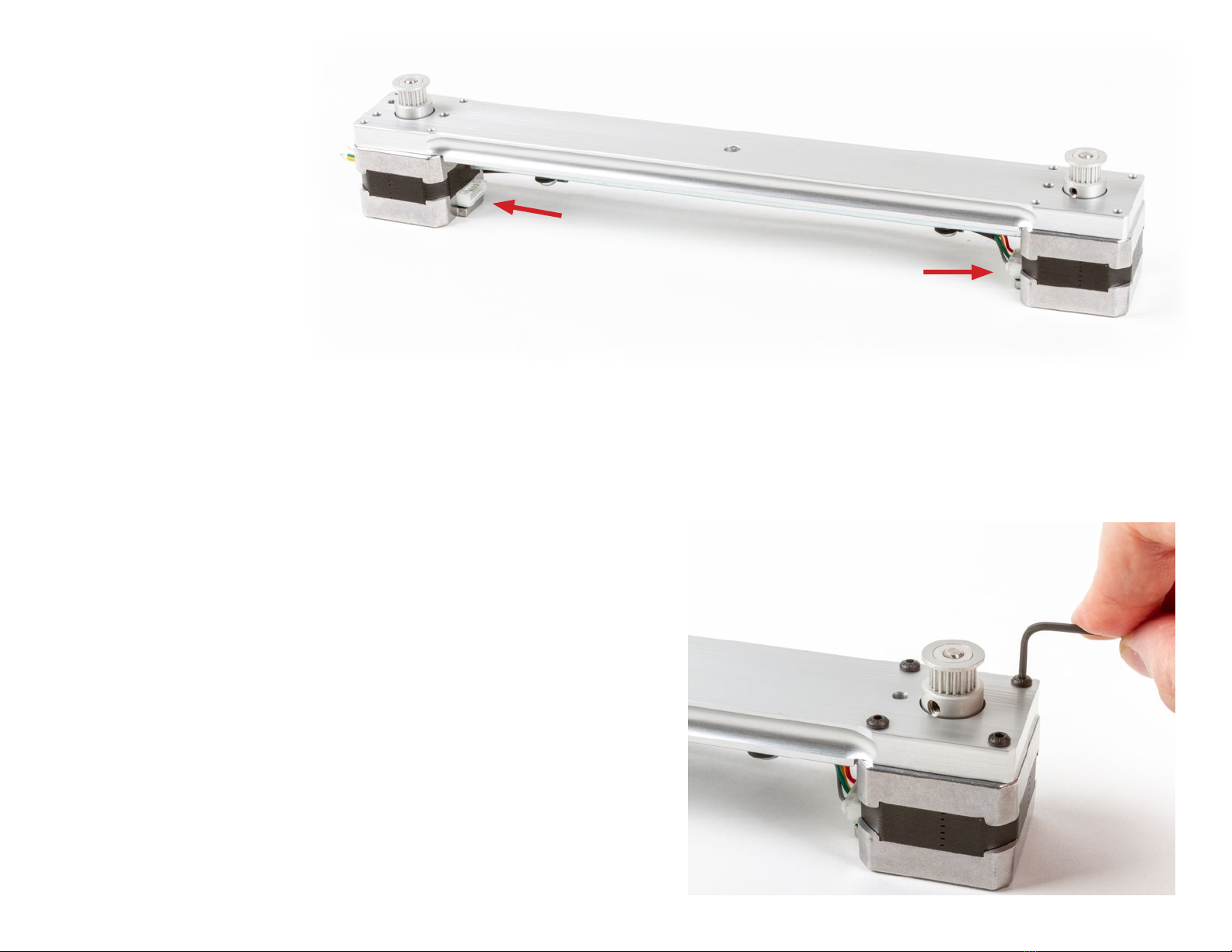
2.4 Install the motors
1. Attach the connector on the Long Motor Wire Harness to one
of the two stepper motors (A).
2. Rotate the motor and feed its pulley through the large hole in
the Base Rail (B), taking care to not pull the cable out of the
loop clamps.
3. Feed the pulley on second motor through the large hole at the
other end of the Base Rail (C). Orient the motor such that its
connector faces towards the center of the Base Rail.
(Continues on next page)
A
CB
14
§2.4 Install the motors, continued
4. Set the Base Rail down on top of the two motors, and check
their orientation: The connectors on both motors should
face towards the center of the base rail (D).
5. Identify the M3×14 Button-head Screws, #15. These can be
identified by their black color and length of approximately 14
mm, as measured below the head. Note that there are also
4 similar-looking but slightly longer M3×16 screws in the kit;
this step requires the 8 shorter ones.
6. Slip four of the M3×14 screws through the four corner holes
around one of the stepper motors, and tighten them in place
(E) with the 2 mm Ball-end Hex L-wrench #3. Lightly snug all
four screws, then tightening all four securely.
7. Repeat this step, adding the other four M3×14 screws to se-
cure the other motor in place.
D
E
15
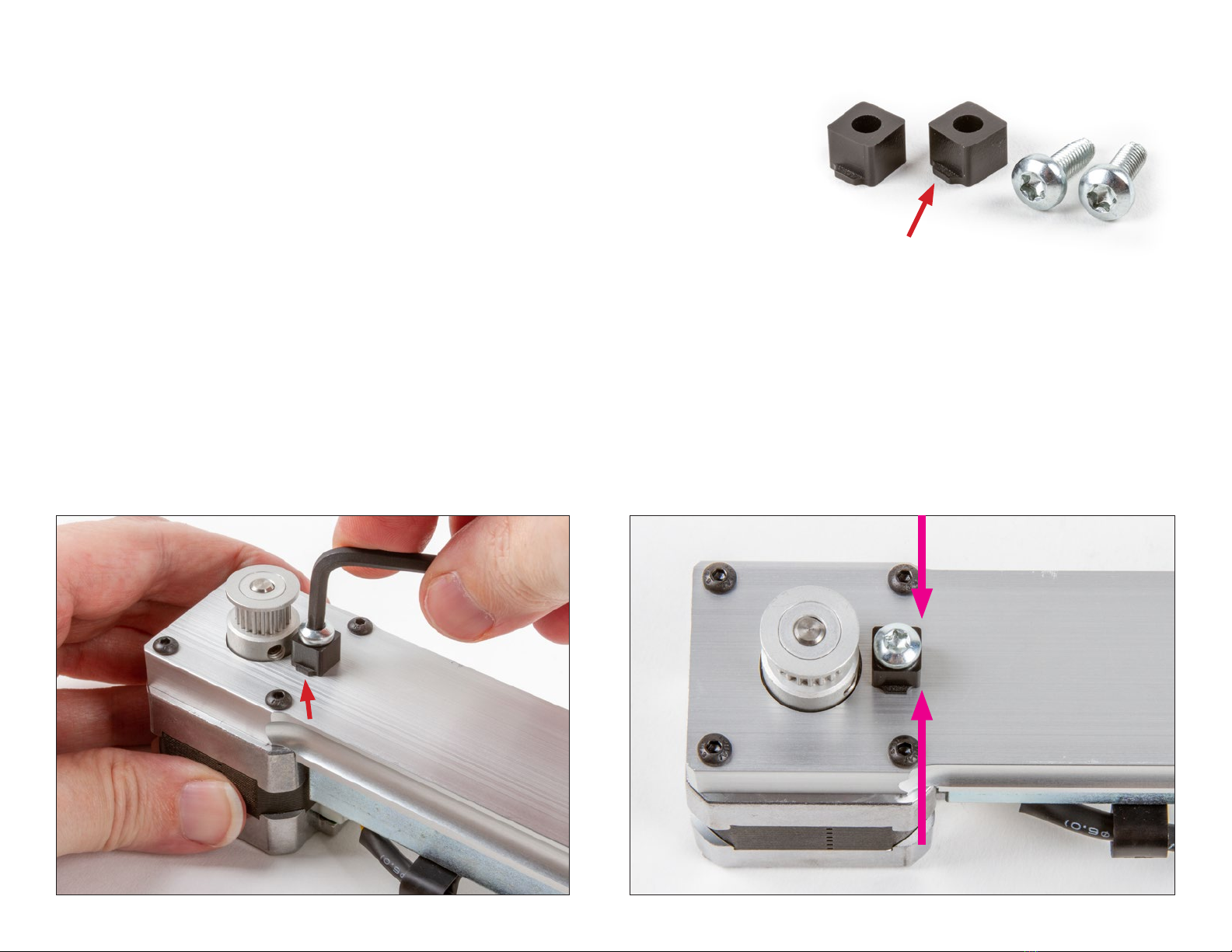
2.5 X Endstops
1. Identify the X Endstops #16 and the M4×12 Torx Tapping Screws, #17.
The X Endstops are black plastic blocks with a hole through the center.
There may be a tab (A) on one side of the Endstop. The screws have
silver color, a star-shaped socket on the head, and a length of approxi-
mately 12 mm, as measured below the head.
2. Slip the screw through an X Endstop, and then install it in the hole next
to one of the timing belt pulleys (B). If there is a tab on the side of the X
Endstop, orient that tab down, against the Base Rail, and pointing back
towards the side with the loop clamps. Use the Torx L-wrench #2 to
thread the screw into place. Repeat for the second X Endstop.
3. Before final tightening, square up each X Endstop so that its four sides
are parallel to those of the Base Rail (C). Once they are square, tighten
them securely.
A
B
C
#16 #17
16
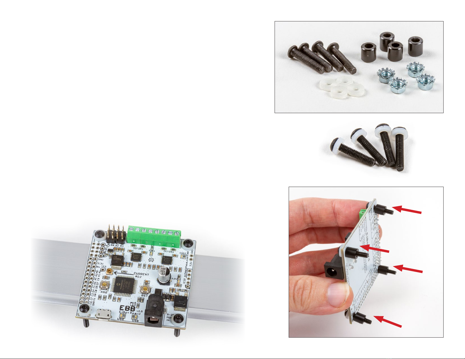
2.6 Mounting the EBB
1. Identify the EBB Driver Board #18, and the EBB Support #19. You
will also need the four long, black M3×16 Button-head Screws #20,
the White Nylon Washers #21, the Black Nylon Spacers #22, and the
M3 Kep Nuts #23. The spacers are short black plastic tubes, and the
nuts are distinguished by having a built-in toothed washer.
2. Slide a white nylon washer over each screw (A), and then insert the
screws through the four corner holes of the EBB (B).
3. Holding the EBB vertically with the power jack facing sideways as
shown (C), slide one of the black nylon spacers over each screw.
Place a finger over each screw head as you slide its spacer on, to
prevent the screw from popping out of the hole.
#18
#21
#22
#23
#20
(Continues on next page)
A
B
C
Tip: Rest the EBB on top of the Base Rail for easy access.
Tip: If you have diculty with this step, it may be helpful to put
a small piece of tape over the screw heads.
17
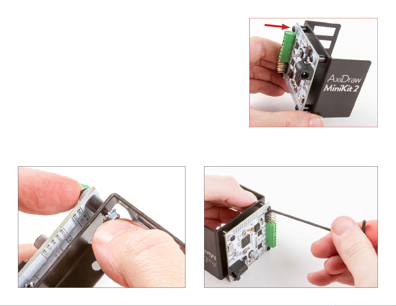
§2.6 Mounting the EBB, continued
4. Orient the EBB Support such that the power jack and USB port face
towards the “Axidraw MiniKit 2” logo. Then, two at a time, guide the
four screws into the corner holes of the EBB support (D).
5. Thread an M3 Kep Nut onto each screw, such that the “teeth” of the
nut point in towards the EBB (E). Then, tighten each screw with your
2 mm Ball-end Hex L-wrench #3, steadying the nut with a finger (F).
6. Check that the EBB and all four of its screws feel securely mounted
in place.
D
EF
(Continues on next page)
#19
Tip: If you have diculty with this step, it may be helpful to
use a small wrench to steady the nut in place. If you do so, take
special care not to over-tighten the screws.
18

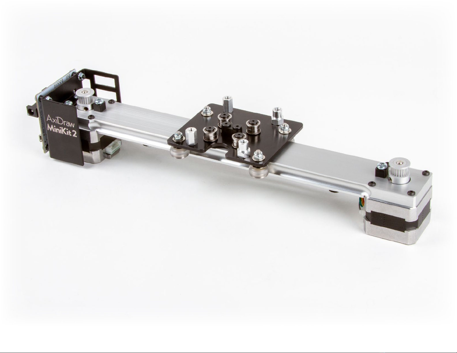
G
7. Attach the EBB Support to the Base Rail, using two of the #24 M4×8 Torx
Tapping Screws. These screws have silver color, a star-shaped socket on the
head, and a length of approximately 8 mm, as measured below the head.
The screws go through the flange in the EBB support and into the two remain-
ing holes on the top of the Base Rail. Use the Torx L-wrench #2 to thread both
screws into place and then tighten both screws securely.
§2.6 Mounting the EBB, continued
Tip: We find it easiest to use the long end of the driver to start each screw,
and then the short end of the driver to tighten it in place.
19
Part 3: The X Carriage 20
Table of contents
Other Evil Mad Scientist Science Education Product manuals

Popular Science Education Product manuals by other brands

DF ROBOT
DF ROBOT Light Chaser manual

KOKEN
KOKEN LM-107A instruction manual

Alga Science
Alga Science BUBBLEMAKERLAB quick start guide

CAE Healthcare
CAE Healthcare lntuity LearningSpace Ultraportable Getting started guide

SNAP CIRCUITS
SNAP CIRCUITS BRIC: STRUCTURES instruction manual

pitsco
pitsco Structures Testing Instrument user guide


