pitsco Structures Testing Instrument User manual

59921 V0217
Structures Testing
Instrument
User Guide

2 Structures Testing Instrument User Guide 59921 V0217
The Structures Testing Instrument oers ne-tuned testing and several unit options.
Using a turn force wheel, you can apply up to 800 pounds of force to structures such as balsa wood or
basswood towers and bridges. You don’t have to destroy the structure to test it to the limit – just apply
pressure in small increments and stop applying pressure at the rst sign of structural damage. And because
the system captures both the peak load (force) and the current load (force) on the display, the load that
breaks the structure is displayed. The tester can display the force in pounds, kilograms, and newtons.
With the tester’s software, you can graph the force as a line chart per structure and print it to analyze it
later. This software also enables you to connect the computer to a projector to display testing data in the
classroom.
Note: Bridges tested should be no longer than the span column support and no wider than the structure
supports. Towers must be no taller than the 11-1/2" threaded rod and no wider than the acrylic tower shield.
Items Included
A. Structures Testing Instrument G. USB cable
B. Acrylic tower shield H. 5-1/2" and 11-1/2" threaded rods
C. 6 roadbed load blocks (6 sizes) I. Tower load plate
D. 2 span columns J. Washer, hex nut, and wing nut
E. 2 structure supports K. Power supply
F. 2 span locking pins
A. Structures Testing Instrument
G. USB
cable
F. 2 span
locking pins
E.
2 structure
supports
D. 2 span
columns
C. 6 roadbed
load blocks
B. Acrylic
tower
shield
K. Power supply
J. Washer, hex nut, and wing nut
I. Tower
load plate
H. Threaded rods
Span column support

Structures Testing Instrument User Guide 59921 V0217 3
Materials and Tools Required (not included)
• Standard 120-volt electrical outlet
• Balsa wood or basswood structure for testing
• Safety glasses
Safety
• This kit is designed and intended for educational purposes only.
• Use only under the direct supervision of an adult who has read and understood the instructions provided
in this user guide.
• Read warnings on packaging and in manual carefully.
• Always wear safety glasses when using the tester or working within 10 feet of the tester.
• Only test balsa wood or basswood structures on the tester.
• Do not exceed 800 pounds of pressure when testing or the tester might be damaged.
• Store the tester in a dry place at room temperature.
• Do not get the tester wet.
Preparing to Test
1. Place the tester on a level, stable surface such as a sturdy desk or table. Make sure the tester is not close to
the surface’s edge.
2. Plug the tester into an electrical outlet.
3. If using the included software to record and
graph testing data, see the Using the Software
section on page 7.
Testing a Bridge
This procedure can also be used to test a truss or
similar structures. If using the software, be sure to
read the directions on page 7 before starting to
test a structure.
1. Place the span columns in the tester’s span
column support, one on either side of the
tester’s center (Figure 1).
2. Place the metal bracket end of each structure
support into the top of each span column
(Figure 2). Do this so that the length of
the support is perpendicular (crosswise)
to the span column support.
3. Set the bridge on top of the structure
supports. Move the supports so the
structure is centered over the middle of
the tester and each end of the bridge’s
roadbed overlaps the supports enough
to securely hold the bridge (usually a half
inch to an inch).
4. Insert the span locking pins into the span
columns to lock them in place (Figure 3).
Remove the bridge.
Figure 1
Figure 2 Figure 3

4 Structures Testing Instrument User Guide 59921 V0217
5. Find the 5-1/2" threaded rod; note how the
threads on one end have been stripped. With this
end up, screw the threaded rod into the center of
the tester until it stops (Figure 4).
6. Turn the tester’s turn force wheel clockwise
until it stops. The load cell indicator should be at
the top. Do not force the wheel any farther. Set
the bridge back on the tester between the two
structure supports.
7. Select a roadbed load block that is the closest to
being two inches shorter than the total length
of the bridge’s roadbed. Slide the block into the
bridge and on top of its roadbed; the load block
will have a hole to t over the top of the threaded
rod (Figure 5).
8. Place the at washer over the rod, followed by
either the wing nut or hex nut (the hex nut is
best for tight spaces). Tighten the nut until it is approximately 1/16" above the load block (Figure 6).
9. Above the digital display, push the Zero button.
The display will show both the force and peak
loads, indicated here by “Force Lbf” and “Peak Lbf.”
(“Lbf” means “force pound.”)
10. Select which unit of measurement you wish to
use: pound or kilogram. To do this, press the Select
button to see the options alternate on the screen.
When you see the measurement you want, press
Select. The tester will return to the force and peak
load display.
11. To apply force to the structure, slowly turn the
force wheel counterclockwise (Figure 7). Continue
to apply pressure appropriate to your testing type.
Choose from the following (on next page):
Figure 4
Figure 5 Figure 6
Figure 7

Structures Testing Instrument User Guide 59921 V0217 5
• Nondestructive test: Using the force wheel, slowly and continuously apply force to the structure
until the measured force reading begins to drop and no longer tracks the peak force. You will often
hear a slight crack or pop come from the structure when this occurs. At this point, the structure
cannot bear any more load without continuing to damage the structure. Stop applying force.
• Destructive test: Apply force until the structure is broken.
The display will ash, make an audible noise, and show “Warning Maximum Force” when maximum force
is reached.
12. If you aren’t using the downloadable software, record the force readings from the test.
13. Remove the nut, washer, load block, and bridge from the tester. Press the Zero button.
Follow Steps 6-13 to test subsequent bridges or
structures, adjusting the width of the span columns as
needed.
Testing a Tower
If using the software, be sure to read the directions on
page 7 before testing a structure.
Note: You do not need the span columns and
structure supports to test towers; however, you do
not have to remove them from the tester unless they
prevent placing the acrylic shield on the tester.
1. If the tester has the 5-1/2" threaded rod in, remove
it and replace it with the 11-1/2" rod. Be sure the
end with the stripped threads is pointing up.
2. Turn the tester’s turn force wheel clockwise until it
stops. The load cell indicator should be at the top.
Do not force the wheel any farther.
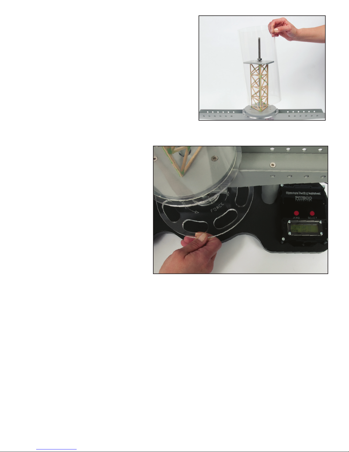
3. Place the tower over the rod (Figure 8).
4. Place the tower load plate over the threaded rod
and set it on top of the tower (Figure 9). Drop
the washer over the rod and onto the load plate
and screw the hex nut (not the wing nut) over
it, stopping approximately 1/16" above the load
plate (Figure 10).
Figure 8
Figure 9 Figure 10
6 Structures Testing Instrument User Guide 59921 V0217
5. Place the acrylic shield over the tower (Figure 11).
6. Above the digital display on the tester, push the Zero
button. The display will show both the force and peak
loads, indicated by “Force Lbf”and“Peak Lbf.”
7. Select which unit of measurement you wish to use:
pound or kilogram. To do this, press the Select button
to see the options alternate on the screen. When you
see the measurement you want, press Select again. The
tester will return to the force and peak load display.
8. To apply force to the structure, slowly turn the force
wheel counterclockwise (Figure 12). Continue to apply
pressure appropriate to your testing type. Choose from
the following:
• Nondestructive test: Using the force wheel, slowly
and continuously apply force to the
structure until the measured force
reading begins to drop and no longer
tracks the peak force. You will often
hear a slight crack or pop come from
the structure when this occurs. At
this point, the structure cannot bear
any more load without continuing to
damage the structure. Stop applying
force.
• Destructive test: Apply force until the
structure is broken.
The display will ash, make an audible
noise, and show“Warning Maximum
Force” when maximum force is reached.
9. If you aren’t using the downloadable
software, record the force readings from
the test.
10. Remove the nut, washer, load plate, and tower from
the tester. Press the Zero button.
11. Follow Steps 2-10 to test subsequent towers.
Figure 12
Figure 11

Structures Testing Instrument User Guide 59921 V0217 7
Using the Software
The tester comes with a USB cable for use with a Windows PC. The software can be found on the Structures
Testing Instrument product page under the Resources tab along with a PDF explaining how to use it.
The software is ideal for enabling the entire class to see the test data by connecting the computer to an
overhead projector or to a large monitor. To do this, follow the projector or monitor’s instructions for
connecting to your computer.
The software also creates a line chart of the test data to give students a visual reference. The chart will record
up to ve minutes, which should be plenty of time for an individual structure test. Each test’s chart and data
display can be printed.

8 Structures Testing Instrument User Guide 59921 V0217
P.O. Box 1708 • Pittsburg, KS 66762
shop.pitsco.com
Toll-Free Orders 800-835-0686
Table of contents
Other pitsco Science Education Product manuals


