EVOAQ Home Ventilation User manual

Ventilation Systems
Installation Manual
Please take the time to read these instructions in full
before commencing your installation.
Careful planning prior to starting work will guarantee
the fastest and best results regarding the installation.
EVOAQ - Air Quality Innovation
28/375 East Tamaki Road
Auckland 2013
09 558 5590
www.evoaq.co.nz
Working in the ceiling space can be a hazard, and all
safety precautions should be used to ensure the
safety of yourself and any others.
EVOAQ
Air Quality Innovation
Home Ventilation

Thank you for your purchase of our company’s products. This system has been
manufactured following current technical safety regulations and is in compliance with
AS/NZ60335 standard.
Please read this instruction booklet carefully before installing the system.
It contains important information on personal and user safety measures to be followed while
installing, using, and carrying out maintenance work on the equipment. Once the product
has been installed, please hand this booklet to the end user.
TRANSPORT AND MANIPULATION
The packaging used for this system has been designed to support normal transporting
conditions. The product must always be transported in its original packaging as not doing so
could deform or damage the product. Do not place heavy weights on the packaging and
avoid knocking or dropping it.
Check that the apparatus is in perfect condition while unpacking. Do not accept delivery if
the apparatus is not in its original packaging or shows clear signs of having been
manipulated in any way. Any fault or damage caused in origin is covered by our company
guarantee. Please make sure that the apparatus coincides with the product you have
ordered and that the details on the rating label fulfil your requirements.
The product should be stored in a dry place in its original packaging, protected from dust
and dirt until it is installed in its final location.
IMPORTANT INFORMATION
Installation must only be carried out by qualified persons. Make sure that the installation
complies with the applicable building and electrical regulations. The fan appliance must not
be used in explosive or corrosive atmospheres. The duct system must be used exclusively
for the ventilation system.
The appliance is not intended for use by young children or infirm persons unless they have
been adequately supervised by a responsible person to ensure that they can use the
appliance safely. Young children should be supervised to ensure that they do not play with
the appliance.
ELECTRICAL CONNECTION
The ventilation fan must be connected to a single-phase mains network, with the specific
voltage and frequency according to the specifications on the fan rating label.
The electrical installation must include an isolating switch with a contact clearance of at least
3 mm, correctly sized and in accordance with the electrical standards.
Earthing is not required as this fan has double insulation (Class II).
If the fan model you have purchased is not fitted with a power cord then please note that it
must be wired with a fixed permanent connection. Disconnect the mains supply before
making any electrical connection. If in any doubt contact a registered electrician.
SAFETY DURING INSTALLATION
Make sure there are no loose elements near the fan, as they could run the risk of being
sucked up by it. When connecting the fan to the ducting, check that the ducting is clean of
any element that could be sucked up by the fan. During installation of the fan, make sure
that all the fittings are in place and that the structure which supports it is resistant enough
to bear its weight at full functioning power.
Fans may have a delayed start-up time or operate under the control of their inbuilt
electronics. Always take extreme care as the unit may start unexpectedly. Before carrying
out any maintenance, make sure the mains supply is disconnected, even if the machine is
switched off. Never insert your hands into the inlet side of the fan without first unplugging
the fan.

INSTALLING THE SYSTEM
Before commencing installation, select a suitable place for the fan to be installed in the
ceiling cavity. It is recommended to place the fan and filter near the manhole for easy access
when carrying out maintenance to the system. Suspend the fan and filter from the ceiling
framing with the chain and cable ties provided in order to minimise the sound levels
resonating through the ceiling framing.
If the system will be taking air from outside or the fan or air inlet is installed in outside
windows or walls, care must be taken to avoid the backflow of gases into the system from
open gas flues or other open-fire appliances.
Attach the inlet side of the fan to the filter frame using the duct tape provided. Connect the
acoustic ducting to the outlet of the fan. The acoustic ducting should be 1-1.5m long and
placed after the fan to eliminate sounds from the fan motor inside the ducting system.
The inlet of the fan unit is the end where you can see the fan blade clearly. There are also
arrows on the unit showing airflow direction.
Spending time planning the layout of the ducting system is important. See the inside page
of this instruction manual for further details and example layouts.
Some simple rules to apply to ensure the best possible results:
• Lay the ducting so there is a roughly equal length of ducting to each diffuser.
• The shortest length of ducting should be no shorter than 3 metres.
• Avoid tight bends in the ducting.
• Ensure the ducting is stretched out fully. Cut the ducting if needed.
• Avoid installing the ducting where it may be crushed or damaged by you or other tradesmen.
• Avoid installing the diffusers near doors/hallways and directly above beds or couches.
If a wall controller is included with the system, this is connected to the fan via the supplied
network cable. The controller is low-voltage only, however to prevent any damage to both
the fan and controller, please ensure that the fan is disconnected from the mains supply
before connecting the controller.
STARTING UP THE FAN
Before starting up the fan, ensure that:
• The apparatus is well secured and the electrical connections have been carried out correctly.
• Any electrical safety devices are correctly connected, adequately adjusted and ready for use.
• The wire and electrical connection inputs are correctly sealed and water-tight.
When starting up the fan, ensure that:
• The propeller turns in the correct direction.
• There are no abnormal vibrations.
If the circuit protection device is tripping during operation, the apparatus must be quickly
disconnected from the mains supply. The whole installation should be carefully checked
before trying to start up the machine again.
When the fan is first powered up, there may be a momentary startup delay of up to 30
second while the fan is calibrating the sensors or checking user input from the wall
controller.

Du
c
t
in
g
✘✓ ✓
Do not install the electronics box upside down as this will damage the fan
FAN INSTALLATION
Some things to consider when installing the fan and the filter:
• Mount the fan and filter so they sit above any ceiling material - ~200mm above the ceiling.
• Hang the fan and filter with the chain and cable ties provided (e.g. see below image).
• Connect 1m acoustic ducting after the fan, not in between the fan and filter.
• To avoid damage to the electronics, ensure the fan body is placed upright (see below).
• For optimal airflows, keep the duct straight and level with the fan.
• Place the fan away from bedrooms to minimise noise issues.
We recommend positioning the fan and filter close to the manhole for easy access for servicing.
The filter should be checked at least every 12 months, and replaced at least every 2 years or
earlier if necessary.
The fan should fit on the filter directly and does not require any ducting to be placed in
between. However if the construction of the roof does not provide enough space to mount the
fan directly onto the filter, you can use a short piece of ducting (recommended length
<500mm) to connect between the two. This ducting does not have to be acoustic ducting.

System Wiring
Ventilation Fan and Controller (optional)
For more information about how to connect the fan, contact us directly.
For wiring of summer kit and heat transfer add-ons, check the
respective manuals or contact us for more information.
Ventilation Controller EVOAQ Ventilation Fan
1
0
m
N
e
t
w
o
r
k
C
a
b
l
e
External Fan Wall Controller
Wall Controller
(or Air Source
Control Box)
External fan (only
used in balanced
or heat transfer)
Cable connection to ventilation fan
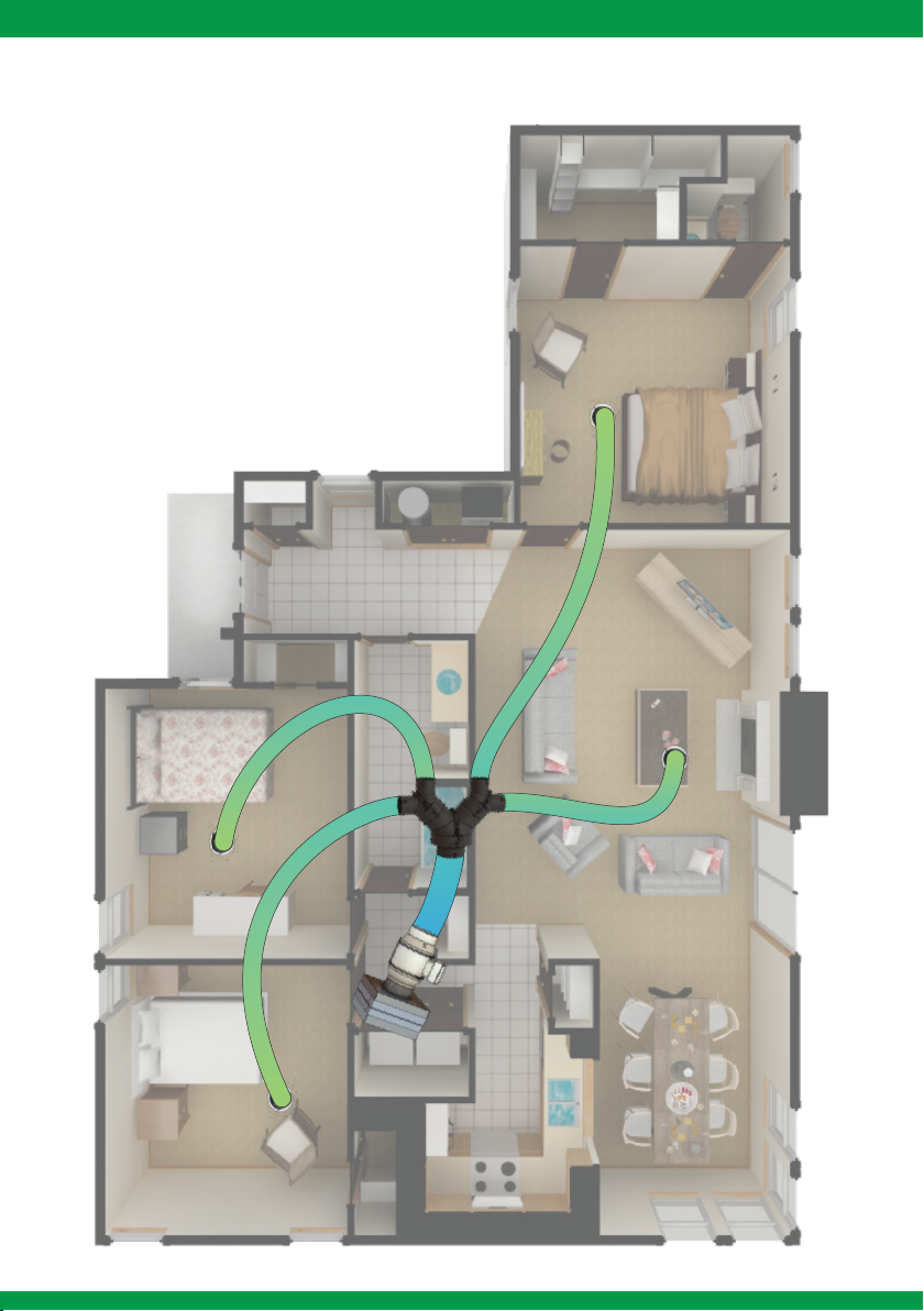
4-Room Sample Layout
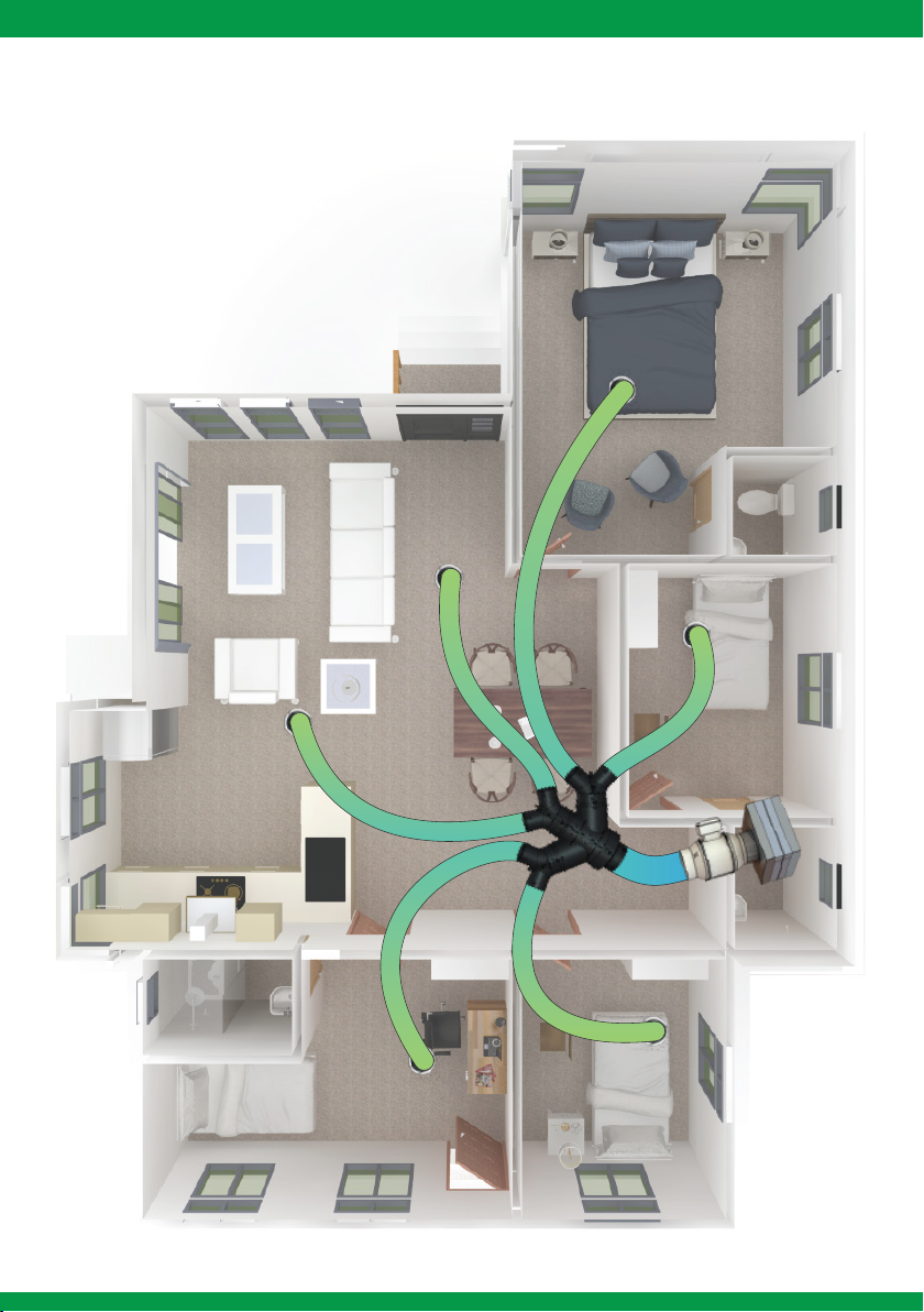
6-Room Sample Layout
For further information, please contact EvolutionFX NZ Limited
Email: [email protected]
Phone: +64 9 558 5590
MAINTENANCE
Before manipulating the fan, make sure it is disconnected from the mains supply - even if it
has previously been switched off. Prevent the possibility of anyone else connecting it while
it is being manipulated.
The apparatus must be regularly inspected. These inspections should be carried out while
bearing in mind the machine's working conditions, taking care to avoid dirt or dust accumu-
lating on the propeller, turbine, motor or grids. This could be dangerous and perceptibly
shorten the working life of the fan unit. While cleaning, great care should be taken not to
damage the propeller.
All maintenance and repair work should be carried out in strict compliance with each coun-
try's current safety regulations.
The fan included with this ventilation system is designed as simply plug in and go
without requiring user intervention.
The smart in-built electronics are constantly monitoring the incoming air quality.
The fan will vary its speed between very low and very high rates (10 - 100%) depending on
the quality of the air to maintain a comfortable and moisture-free indoor environment.
This system is capable of ventilating at very low rates while still bringing in enough fresh air
into the house in situations where other systems would simply switch off.
Maintaining correct ventilation of the house is important in order to prevent heat and energy
losses and to allow you to enjoy a healthier indoor environment.
EVOAQ
Air Quality Innovation
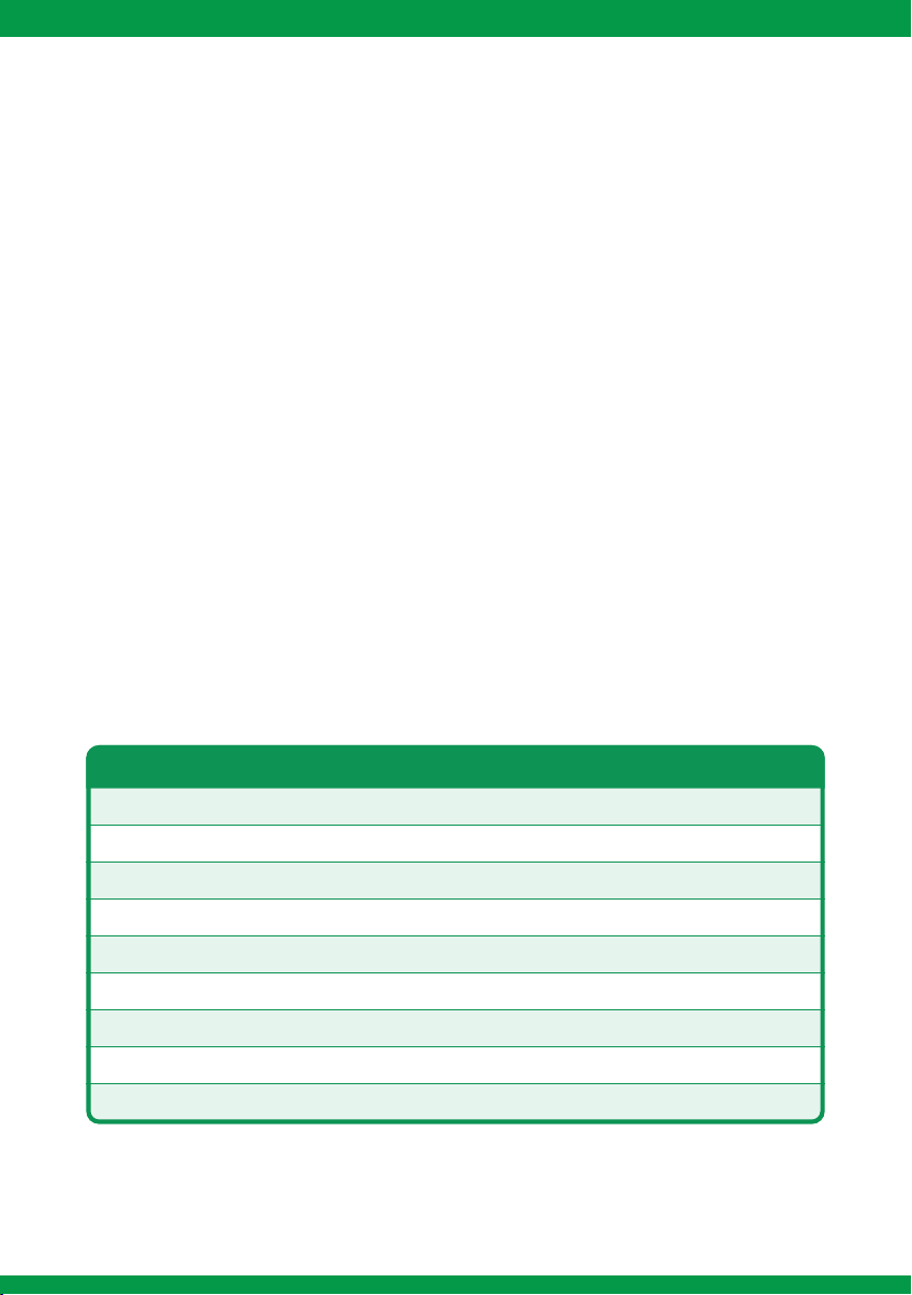
EVOAQ Ventilation Fan Specifications
Fan Size
Voltage (V/Hz)
Power (W)
Air Flow (m³/hr)
Static Pressure (Pa)
Noise Level (dB)
Speed (RPM)
Weight (kg)
Specific Fan Power (SFP)
200mm
230 / 50
3 - 165
63 ~ 1228
580
38
500 - 3000
3.5
0.294 W/Ls-1
150mm
230 / 50
3 - 73
65 ~ 650
457
31
500 - 3000
2.5
0.398 W/Ls-1
125mm
230 / 50
2 - 17
65 ~ 284
159
28
250 - 2250
2.5
0.175 W/Ls-1
Table of contents
Other EVOAQ Fan manuals

EVOAQ
EVOAQ EX-MF EC Series User manual

EVOAQ
EVOAQ AQ60 User manual

EVOAQ
EVOAQ AQ60 User manual

EVOAQ
EVOAQ EX-AX150SF User manual

EVOAQ
EVOAQ EX-AX150MC User manual

EVOAQ
EVOAQ EX-TW150MC User manual

EVOAQ
EVOAQ Summer Upgrade Kit User manual

EVOAQ
EVOAQ EX-TW150SF User manual

EVOAQ
EVOAQ EX-TW180DC User manual

EVOAQ
EVOAQ EX-AX150MC User manual
Popular Fan manuals by other brands

Broan
Broan LOSONE SELECT L900L instructions

Klimatronic
Klimatronic CoolBreeze 3500 Monsun Vario instruction manual

Hunter
Hunter Sonic installation manual

ayas
ayas OBRA Series instruction manual

Casablanca
Casablanca bel-air manual

Kampmann
Kampmann Venkon XL Assembly, installation and operating instructions


