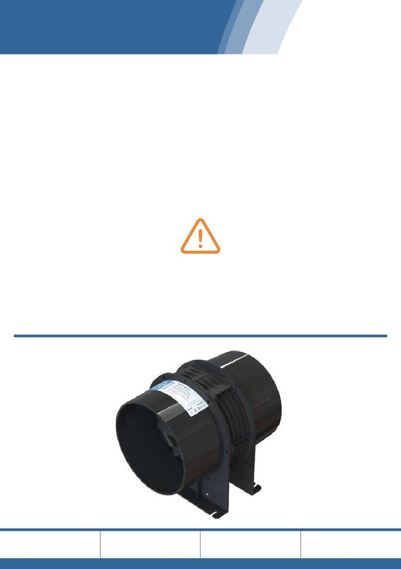
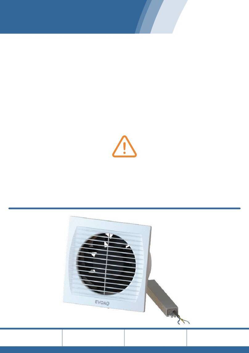
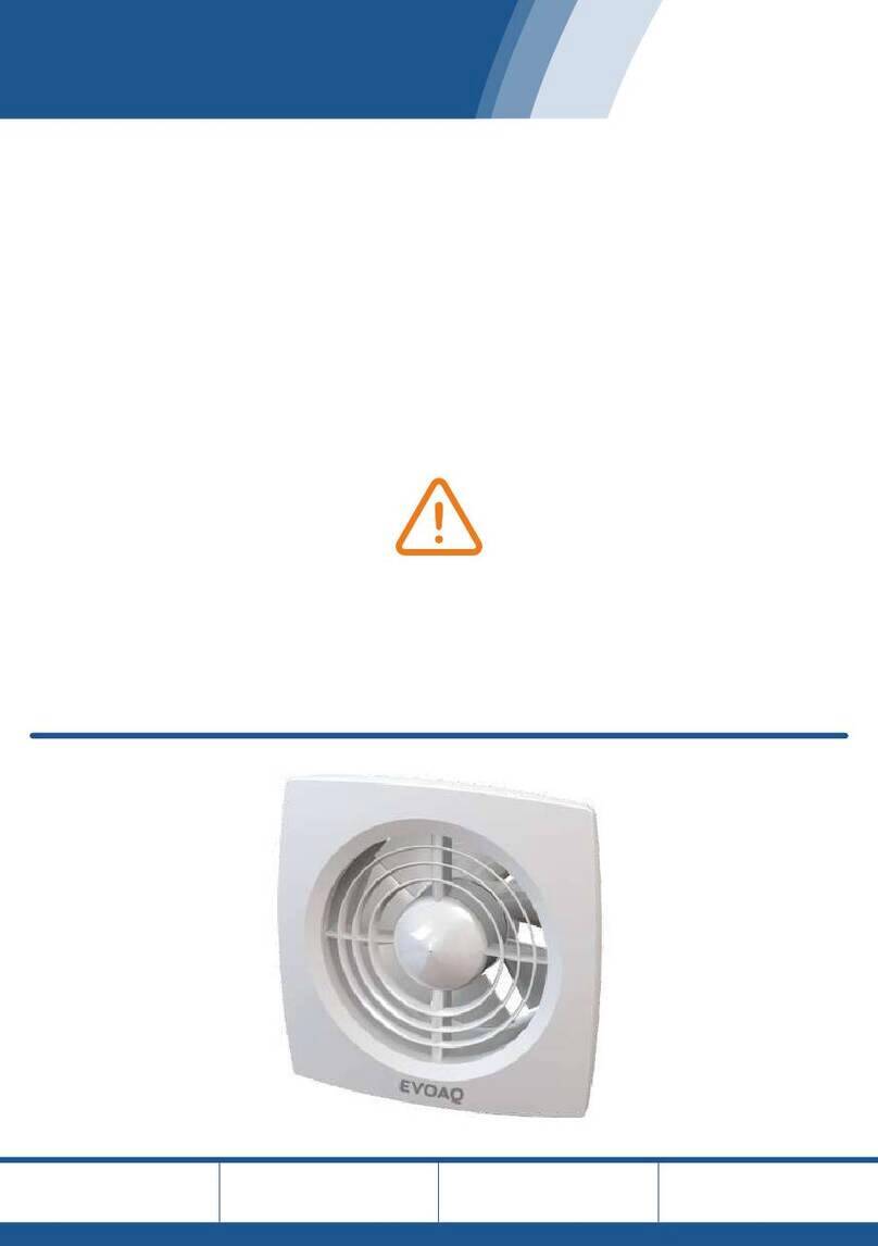
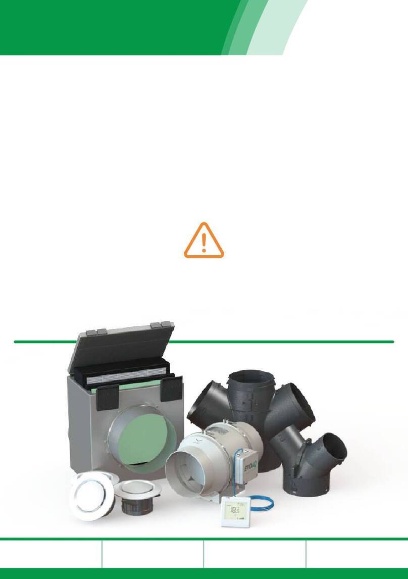
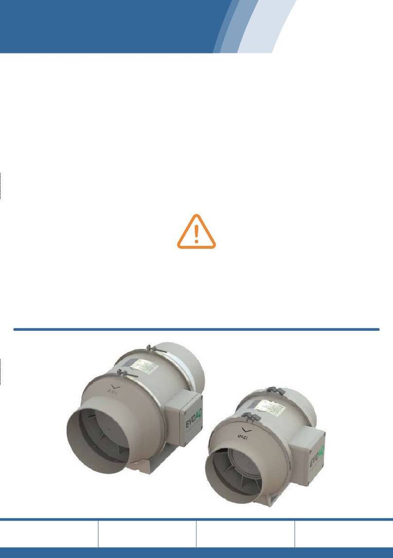
EVOAQ AQ60 User manual

EVOAQ
Air Quality Innovation
Home Ventilation
Installation Manual
Please take the time to read these instructions in full before
commencing your installation.
Careful planning prior to starting work will guarantee the
fastest and best results regarding the installation.
Working in the ceiling space can be a hazard, and all
safety precautions should be used to ensure the
safety of yourself and any others.
Upgrade Models
AQ-HEAT-KIT-xxx
Software Versions
V3.2 (Vent), V3.4 (HT)
Manual Version
V3.3.0 11-2023
Ventilation w.
Heat Transfer

Installation Manual
EVOAQ Ventilation with Heat Transfer Upgrade
Thank you for your purchase of our company’s product. It has been manufactured following
current technical safety regulations and is in compliance with AS/NZ60335 standard.
Please read this instruction booklet carefully before installing or starting up the
product.
It contains important information on personal and user safety measures to be followed while
installing, using, and carrying out maintenance work on the equipment. Once the product
has been installed, please hand this booklet to the end user.
The fans and electronics included with this system are designed as simply plug in
and go while requiring very little user intervention.
The system includes 2 fans, one for ventilation and one for heat transfer. Both fans contain
smart in-built electronics which are constantly monitoring temperature and humidity levels
of the air flowing through the fans. They use this information as well the the settings from
the wall controller to determine what speed to run at, varying their speed between very low-
and very high rates (10 - 100%) as required.
In ventilation mode, the system is designed to supply fresh air to all living areas in the house
at a rate at which the thermal comfort of the house is not affected by the ventilation system.
The heat transfer fan is turned off in this mode.
In heat transfer mode, the heat transfer fan takes excess heat from the heat source room
and redistributes it to the bedrooms. In this mode the ventilation fan continues to provide
fresh air to the heat source room, which is distributed throughout the rest of the house by
the heat transfer fan.
The heat transfer fan is designed to continue transferring heat at low levels even while the
heat source room is cooling down (e.g. at night when everyone has gone to bed) and as long
as there is still some lingering heat that the bedrooms may benefit from. Maintaining correct
ventilation even while heat transfer is active is important in order to prevent condensation
issues and energy losses and to allow you to enjoy a healthier indoor environment.
INSTALLATION OVERVIEW
Before commencing installation, select suitable places for the fans and filter box to be
installed in the ceiling cavity. It is recommended to place the filter and ventilation fan near
the manhole for easy access when carrying out maintenance to the system. Place the filter
before the fan to protect the fan from dust and dirt buildup. Place the heat transfer fan close
to the manhole if possible, and if not possible ensure it is placed in a location that is easily
accessible for servicing.
Suspend the fans from the ceiling framing with the chain and cable ties provided in order to
minimise the sound levels resonating through the ceiling framing.
If the ventilation system will be taking air from outside or the fan or air inlet is installed in
external walls, care must be taken to avoid the backflow of gases into the system from gas
califonts, open gas flues, or other open-fire appliances.
Acoustic ducting is provided for the reduction of fan motor noise. Connect 1-1.5m of acoustic
ducting to the outlet of each fan, and 2-3m of acoustic ducting to the inlet side of the heat
transfer fan (between the inlet grille and fan). Ensure both the inner ducting and outer
sleeve are fully taped onto the fan, and the outer sleeve of the acoustic ducting is without
tears or holes.
Spending time planning the layout of the ducting system is important. See the inside page
of this instruction manual for further details and example layouts.
Take care not to place the heat transfer inlet grille too close (within 1.5m) to the heat source,
as the air generated can exceed the temperatures that the fan is designed to operate under.
If the intake air is too hot the fan may shut down or be damaged. We recommend placing
the heat transfer inlet grille 3-6m away from the heat source where possible.
Please note:
The inlet of the fan unit is on the side of the fan blades, the side that is not obstructed by
the fan frame. There are also arrows on the unit and rating label showing airflow direction.
Please be aware that the system is designed for air to flow from the filter box, through the
ventilation fan, and to the rest of the house on the ventilation side, and for air to flow from
the inlet grille, through the heat transfer fan, and into the bedrooms on the heat transfer
side. Ensure the fans are oriented correctly for this during installation.
Spending time planning the layout of the ducting system is important. See the inside page
of this instruction manual for further details and example layouts.
Some simple rules to apply to ensure the best possible results:
•
•
•
•
•
•
•
•
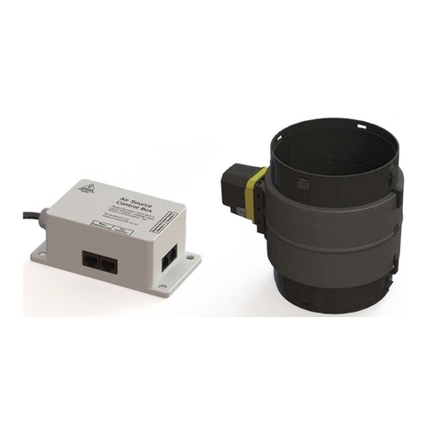
The wall controller included with this system is connected to the air source control box via
the supplied network cable. The controller is low-voltage only, however to prevent any
damage to the electronics please ensure that the fans are disconnected from the mains
supply before connecting or disconnecting any network cables.
Important information for the safety of installers and user:
Installation must only be carried out by qualified persons. Make sure that the installation
complies with the applicable building and electrical regulations. This apparatus must not be
used in explosive or corrosive atmospheres.
This appliance is not intended for use by young children or infirm persons unless they have
been adequately supervised by a responsible person to ensure that they can use the
appliance safely. Young children should be supervised to ensure that they do not play with
the appliance.
TRANSPORT AND MANIPULATION
The packaging used for this apparatus has been designed to support normal transporting
conditions. The apparatus must always be transported in its original packaging as not doing
so could deform or damage the product. Do not place heavy weights on the packed product
and avoid knocking or dropping it.
The product should be stored in a dry place in its original packaging, protected from dust
and dirt until it is installed in its final location. Do not accept delivery if the apparatus is not
in its original packaging or shows clear signs of having been manipulated in any way.
Check that the apparatus is in perfect condition while unpacking. Any fault or damage
caused in origin is covered by our company guarantee. Please make sure that the apparatus
coincides with the product you have ordered and that the details on the rating label fulfil
your requirements.
ELECTRICAL CONNECTION
The fans must be connected to a single-phase mains network, with the specific voltage and
frequency according to the specifications on the fan rating labels and in accordance with New
Zealand electrical standards.
If any of the electronics included in this system are fitted with a power plug then please note
removing this plug will void the warranty of the product.
In case of damage to the power plug, cord, or device itself, switch off the device and do not
tamper with it. Damaged product must only be repaired or replaced exclusively by the
manufacturer or by an appointed representative. Failure to comply with the above may
endanger the safety of people and cause possible damage to the whole system.
SAFETY DURING INSTALLATION
Make sure there are no loose elements near the fan, as they could run the risk of being
sucked up by it. When connecting the fan to the ducting, check that the ducting is clean of
any element that could be sucked up by the fan. When installing the fan, make sure that all
the fittings are in place and that the structure which supports it is resistant enough to bear
its weight at full functioning power.
Before installing the fan, make sure the mains supply is disconnected, even if the system is
switched off.
FAN INSTALLATION
Some things to consider when installing the fan:
•
•
•
•
•
•
STARTING UP THE FAN
Fans may have delayed startup, or may operate under the control of the inbuilt controlling
electronics included with the fan. Always take extreme care as the fan may start
unexpectedly. Before carrying out any maintenance, make sure the mains supply is
disconnected, even if the machine is switched off. Never insert your hands into the inlet side
of the fan without first unplugging the fan.
Before starting up the fan, ensure that:
•
•
•
•
When starting up the fan, ensure that:
•
•
If the circuit protection device is tripping during operation, the apparatus must be quickly
disconnected from the mains supply. The whole installation should be carefully checked
before trying to start up the machine again.
MAINTENANCE AND REPAIR
Before servicing the fan, make sure it is disconnected from the mains supply - even if it has
previously been switched off. Avoid the risk of anyone else plugging it in while you’re
working on it.
The fan must be regularly inspected. These inspections should consider the fan’s working
conditions, ensuring no dirt or dust builds up on the propeller, turbine, motor or grilles. This
could be dangerous and perceptibly shorten the fan’s lifespan. While cleaning, take extra
care not to damage the propeller. The filters should be checked at least every 12 months, and
replaced at least every 2 years, or earlier if necessary. Any and all maintenance work should
be carried out in strict compliance with New Zealand safety regulations.
All our products contain repairable or replaceable parts. Repair or replacement of these parts
should only be handled by the manufacturer. In the case of damage or malfunction of the
fan, please contact the manufacturer or installer to arrange for repair. Please note that a
small fee may apply for repair services not covered under warranty.
SYSTEM WIRING
This system should be permanently powered via the ventilation fan.
Both fans are fitted with a power plug; if there are no power points available for the fans
these should be installed by a registered electrician. The wall controller is connected via a
network cable; as this cable is low-voltage it does not need to be wired by an electrician.
SYSTEM OPERATION
Before installing the system, it is important to understand how it works. The fans are
controlled by internal electronics and sensors, and the system operation mode can be
adjusted using the wall controller provided. Refer to the wall controller manual for more
detailed instructions on controller operation.
This system is designed to not be turned off, in order to provide constant ventilation to the
house and as such maintain a healthy and comfortable living environment. Using 2 fans
together allows the system to provide low-level ventilation even while heat transfer is active.
Ventilation Mode Operation
In ventilation mode the heat transfer fan is turned off. The damper is opened, and the
ventilation fan supplies fresh air to all living areas. The back-draft shutter on the heat
transfer fan stops air from going back through the heat transfer inlet grille instead of the
bedrooms.
The ventilation fan is constantly monitoring the incoming air quality and will vary its speed
between very low and very high rates (10 - 100%) depending on air quality and the selected
ventilation rate to maintain a comfortable and moisture-free indoor environment. This is
how the ventilation fan is capable of ventilating at very low rates while still bringing in
enough fresh air into the house in situations where other systems would simply switch off.
Heat Transfer Mode Operation
In heat transfer mode, the damper closes and the ventilation fan runs at the low ventilation
rate, providing fresh air to the heat source room, as well as any other living areas connected
to the ventilation side only. The air in the heat source room is heated, and then distributed
to the rest of the house via the heat transfer fan.
The heat transfer fan first runs at a trickle speed, in order to sense the air temperature going
through the fan. Once the room heats up and there is excess heat available to be
transferred, the heat transfer fan will speed up and start the heat transfer process, adjusting
its speed based on how much heat is available.
When the heat source is no longer providing heat (e.g. fire has died down), the fan will start
slowing down, continuing to transfer any remaining heat in the room. Once no more heat is
left to be transferred, the fan will slow down again to continue running at a trickle speed -
until the room heats up once again and heat transfer starts again.
EvolutionFX Limited reserves the right to change specifications or designs described in this
document without notice and without obligation.
For further information, please contact EvolutionFX NZ Limited
email: info@evolutionfx.co.nz
phone: +64 9 558 5590
EVOAQ EVOAQ
Air Quality Innovation
EVOAQ Ventilation w. Heat Transfer
Page 2 www.evoaq.co.nz

Installation Manual
EVOAQ Ventilation with Heat Transfer Upgrade
Thank you for your purchase of our company’s product. It has been manufactured following
current technical safety regulations and is in compliance with AS/NZ60335 standard.
Please read this instruction booklet carefully before installing or starting up the
product.
It contains important information on personal and user safety measures to be followed while
installing, using, and carrying out maintenance work on the equipment. Once the product
has been installed, please hand this booklet to the end user.
The fans and electronics included with this system are designed as simply plug in
and go while requiring very little user intervention.
The system includes 2 fans, one for ventilation and one for heat transfer. Both fans contain
smart in-built electronics which are constantly monitoring temperature and humidity levels
of the air flowing through the fans. They use this information as well the the settings from
the wall controller to determine what speed to run at, varying their speed between very low-
and very high rates (10 - 100%) as required.
In ventilation mode, the system is designed to supply fresh air to all living areas in the house
at a rate at which the thermal comfort of the house is not affected by the ventilation system.
The heat transfer fan is turned off in this mode.
In heat transfer mode, the heat transfer fan takes excess heat from the heat source room
and redistributes it to the bedrooms. In this mode the ventilation fan continues to provide
fresh air to the heat source room, which is distributed throughout the rest of the house by
the heat transfer fan.
The heat transfer fan is designed to continue transferring heat at low levels even while the
heat source room is cooling down (e.g. at night when everyone has gone to bed) and as long
as there is still some lingering heat that the bedrooms may benefit from. Maintaining correct
ventilation even while heat transfer is active is important in order to prevent condensation
issues and energy losses and to allow you to enjoy a healthier indoor environment.
INSTALLATION OVERVIEW
Before commencing installation, select suitable places for the fans and filter box to be
installed in the ceiling cavity. It is recommended to place the filter and ventilation fan near
the manhole for easy access when carrying out maintenance to the system. Place the filter
before the fan to protect the fan from dust and dirt buildup. Place the heat transfer fan close
to the manhole if possible, and if not possible ensure it is placed in a location that is easily
accessible for servicing.
Suspend the fans from the ceiling framing with the chain and cable ties provided in order to
minimise the sound levels resonating through the ceiling framing.
If the ventilation system will be taking air from outside or the fan or air inlet is installed in
external walls, care must be taken to avoid the backflow of gases into the system from gas
califonts, open gas flues, or other open-fire appliances.
Acoustic ducting is provided for the reduction of fan motor noise. Connect 1-1.5m of acoustic
ducting to the outlet of each fan, and 2-3m of acoustic ducting to the inlet side of the heat
transfer fan (between the inlet grille and fan). Ensure both the inner ducting and outer
sleeve are fully taped onto the fan, and the outer sleeve of the acoustic ducting is without
tears or holes.
Spending time planning the layout of the ducting system is important. See the inside page
of this instruction manual for further details and example layouts.
Take care not to place the heat transfer inlet grille too close (within 1.5m) to the heat source,
as the air generated can exceed the temperatures that the fan is designed to operate under.
If the intake air is too hot the fan may shut down or be damaged. We recommend placing
the heat transfer inlet grille 3-6m away from the heat source where possible.
Please note:
The inlet of the fan unit is on the side of the fan blades, the side that is not obstructed by
the fan frame. There are also arrows on the unit and rating label showing airflow direction.
Please be aware that the system is designed for air to flow from the filter box, through the
ventilation fan, and to the rest of the house on the ventilation side, and for air to flow from
the inlet grille, through the heat transfer fan, and into the bedrooms on the heat transfer
side. Ensure the fans are oriented correctly for this during installation.
Spending time planning the layout of the ducting system is important. See the inside page
of this instruction manual for further details and example layouts.
Some simple rules to apply to ensure the best possible results:
•
•
•
•
•
•
•
•
The wall controller included with this system is connected to the air source control box via
the supplied network cable. The controller is low-voltage only, however to prevent any
damage to the electronics please ensure that the fans are disconnected from the mains
supply before connecting or disconnecting any network cables.
Important information for the safety of installers and user:
Installation must only be carried out by qualified persons. Make sure that the installation
complies with the applicable building and electrical regulations. This apparatus must not be
used in explosive or corrosive atmospheres.
This appliance is not intended for use by young children or infirm persons unless they have
been adequately supervised by a responsible person to ensure that they can use the
appliance safely. Young children should be supervised to ensure that they do not play with
the appliance.
TRANSPORT AND MANIPULATION
The packaging used for this apparatus has been designed to support normal transporting
conditions. The apparatus must always be transported in its original packaging as not doing
so could deform or damage the product. Do not place heavy weights on the packed product
and avoid knocking or dropping it.
The product should be stored in a dry place in its original packaging, protected from dust
and dirt until it is installed in its final location. Do not accept delivery if the apparatus is not
in its original packaging or shows clear signs of having been manipulated in any way.
Check that the apparatus is in perfect condition while unpacking. Any fault or damage
caused in origin is covered by our company guarantee. Please make sure that the apparatus
coincides with the product you have ordered and that the details on the rating label fulfil
your requirements.
ELECTRICAL CONNECTION
The fans must be connected to a single-phase mains network, with the specific voltage and
frequency according to the specifications on the fan rating labels and in accordance with New
Zealand electrical standards.
If any of the electronics included in this system are fitted with a power plug then please note
removing this plug will void the warranty of the product.
In case of damage to the power plug, cord, or device itself, switch off the device and do not
tamper with it. Damaged product must only be repaired or replaced exclusively by the
manufacturer or by an appointed representative. Failure to comply with the above may
endanger the safety of people and cause possible damage to the whole system.
SAFETY DURING INSTALLATION
Make sure there are no loose elements near the fan, as they could run the risk of being
sucked up by it. When connecting the fan to the ducting, check that the ducting is clean of
any element that could be sucked up by the fan. When installing the fan, make sure that all
the fittings are in place and that the structure which supports it is resistant enough to bear
its weight at full functioning power.
Before installing the fan, make sure the mains supply is disconnected, even if the system is
switched off.
FAN INSTALLATION
Some things to consider when installing the fan:
•
•
•
•
•
•
STARTING UP THE FAN
Fans may have delayed startup, or may operate under the control of the inbuilt controlling
electronics included with the fan. Always take extreme care as the fan may start
unexpectedly. Before carrying out any maintenance, make sure the mains supply is
disconnected, even if the machine is switched off. Never insert your hands into the inlet side
of the fan without first unplugging the fan.
Before starting up the fan, ensure that:
•
•
•
•
When starting up the fan, ensure that:
•
•
If the circuit protection device is tripping during operation, the apparatus must be quickly
disconnected from the mains supply. The whole installation should be carefully checked
before trying to start up the machine again.
MAINTENANCE AND REPAIR
Before servicing the fan, make sure it is disconnected from the mains supply - even if it has
previously been switched off. Avoid the risk of anyone else plugging it in while you’re
working on it.
The fan must be regularly inspected. These inspections should consider the fan’s working
conditions, ensuring no dirt or dust builds up on the propeller, turbine, motor or grilles. This
could be dangerous and perceptibly shorten the fan’s lifespan. While cleaning, take extra
care not to damage the propeller. The filters should be checked at least every 12 months, and
replaced at least every 2 years, or earlier if necessary. Any and all maintenance work should
be carried out in strict compliance with New Zealand safety regulations.
All our products contain repairable or replaceable parts. Repair or replacement of these parts
should only be handled by the manufacturer. In the case of damage or malfunction of the
fan, please contact the manufacturer or installer to arrange for repair. Please note that a
small fee may apply for repair services not covered under warranty.
SYSTEM WIRING
This system should be permanently powered via the ventilation fan.
Both fans are fitted with a power plug; if there are no power points available for the fans
these should be installed by a registered electrician. The wall controller is connected via a
network cable; as this cable is low-voltage it does not need to be wired by an electrician.
SYSTEM OPERATION
Before installing the system, it is important to understand how it works. The fans are
controlled by internal electronics and sensors, and the system operation mode can be
adjusted using the wall controller provided. Refer to the wall controller manual for more
detailed instructions on controller operation.
This system is designed to not be turned off, in order to provide constant ventilation to the
house and as such maintain a healthy and comfortable living environment. Using 2 fans
together allows the system to provide low-level ventilation even while heat transfer is active.
Ventilation Mode Operation
In ventilation mode the heat transfer fan is turned off. The damper is opened, and the
ventilation fan supplies fresh air to all living areas. The back-draft shutter on the heat
transfer fan stops air from going back through the heat transfer inlet grille instead of the
bedrooms.
The ventilation fan is constantly monitoring the incoming air quality and will vary its speed
between very low and very high rates (10 - 100%) depending on air quality and the selected
ventilation rate to maintain a comfortable and moisture-free indoor environment. This is
how the ventilation fan is capable of ventilating at very low rates while still bringing in
enough fresh air into the house in situations where other systems would simply switch off.
Heat Transfer Mode Operation
In heat transfer mode, the damper closes and the ventilation fan runs at the low ventilation
rate, providing fresh air to the heat source room, as well as any other living areas connected
to the ventilation side only. The air in the heat source room is heated, and then distributed
to the rest of the house via the heat transfer fan.
The heat transfer fan first runs at a trickle speed, in order to sense the air temperature going
through the fan. Once the room heats up and there is excess heat available to be
transferred, the heat transfer fan will speed up and start the heat transfer process, adjusting
its speed based on how much heat is available.
When the heat source is no longer providing heat (e.g. fire has died down), the fan will start
slowing down, continuing to transfer any remaining heat in the room. Once no more heat is
left to be transferred, the fan will slow down again to continue running at a trickle speed -
until the room heats up once again and heat transfer starts again.
EvolutionFX Limited reserves the right to change specifications or designs described in this
document without notice and without obligation.
For further information, please contact EvolutionFX NZ Limited
email: info@evolutionfx.co.nz
phone: +64 9 558 5590
Page 3www.evoaq.co.nz
Place the fans and filter box in an easily accessible location for maintenance;
Lay the ducting so there is a similar length of ducting to each diffuser where possible;
Ensure each total length of ducting from fan to grille is no shorter than 3 metres;
Avoid tight bends in the ducting;
Ensure the ducting is stretched out fully. Cut the ducting where needed;
Ensure the inner duct of the insulated ducting, and both layers of the acoustic ducting
are securely taped;
Avoid installing the ducting where it may be crushed or damaged by you or other
tradespeople;
Avoid installing the diffusers near doors/hallways and directly above beds or
couches.
EVOAQ
Air Quality Innovation
EVOAQ Ventilation w. Heat Transfer

Installation Manual
EVOAQ Ventilation with Heat Transfer Upgrade
Thank you for your purchase of our company’s product. It has been manufactured following
current technical safety regulations and is in compliance with AS/NZ60335 standard.
Please read this instruction booklet carefully before installing or starting up the
product.
It contains important information on personal and user safety measures to be followed while
installing, using, and carrying out maintenance work on the equipment. Once the product
has been installed, please hand this booklet to the end user.
The fans and electronics included with this system are designed as simply plug in
and go while requiring very little user intervention.
The system includes 2 fans, one for ventilation and one for heat transfer. Both fans contain
smart in-built electronics which are constantly monitoring temperature and humidity levels
of the air flowing through the fans. They use this information as well the the settings from
the wall controller to determine what speed to run at, varying their speed between very low-
and very high rates (10 - 100%) as required.
In ventilation mode, the system is designed to supply fresh air to all living areas in the house
at a rate at which the thermal comfort of the house is not affected by the ventilation system.
The heat transfer fan is turned off in this mode.
In heat transfer mode, the heat transfer fan takes excess heat from the heat source room
and redistributes it to the bedrooms. In this mode the ventilation fan continues to provide
fresh air to the heat source room, which is distributed throughout the rest of the house by
the heat transfer fan.
The heat transfer fan is designed to continue transferring heat at low levels even while the
heat source room is cooling down (e.g. at night when everyone has gone to bed) and as long
as there is still some lingering heat that the bedrooms may benefit from. Maintaining correct
ventilation even while heat transfer is active is important in order to prevent condensation
issues and energy losses and to allow you to enjoy a healthier indoor environment.
INSTALLATION OVERVIEW
Before commencing installation, select suitable places for the fans and filter box to be
installed in the ceiling cavity. It is recommended to place the filter and ventilation fan near
the manhole for easy access when carrying out maintenance to the system. Place the filter
before the fan to protect the fan from dust and dirt buildup. Place the heat transfer fan close
to the manhole if possible, and if not possible ensure it is placed in a location that is easily
accessible for servicing.
Suspend the fans from the ceiling framing with the chain and cable ties provided in order to
minimise the sound levels resonating through the ceiling framing.
If the ventilation system will be taking air from outside or the fan or air inlet is installed in
external walls, care must be taken to avoid the backflow of gases into the system from gas
califonts, open gas flues, or other open-fire appliances.
Acoustic ducting is provided for the reduction of fan motor noise. Connect 1-1.5m of acoustic
ducting to the outlet of each fan, and 2-3m of acoustic ducting to the inlet side of the heat
transfer fan (between the inlet grille and fan). Ensure both the inner ducting and outer
sleeve are fully taped onto the fan, and the outer sleeve of the acoustic ducting is without
tears or holes.
Spending time planning the layout of the ducting system is important. See the inside page
of this instruction manual for further details and example layouts.
Take care not to place the heat transfer inlet grille too close (within 1.5m) to the heat source,
as the air generated can exceed the temperatures that the fan is designed to operate under.
If the intake air is too hot the fan may shut down or be damaged. We recommend placing
the heat transfer inlet grille 3-6m away from the heat source where possible.
Please note:
The inlet of the fan unit is on the side of the fan blades, the side that is not obstructed by
the fan frame. There are also arrows on the unit and rating label showing airflow direction.
Please be aware that the system is designed for air to flow from the filter box, through the
ventilation fan, and to the rest of the house on the ventilation side, and for air to flow from
the inlet grille, through the heat transfer fan, and into the bedrooms on the heat transfer
side. Ensure the fans are oriented correctly for this during installation.
Spending time planning the layout of the ducting system is important. See the inside page
of this instruction manual for further details and example layouts.
Some simple rules to apply to ensure the best possible results:
•
•
•
•
•
•
•
•
The wall controller included with this system is connected to the air source control box via
the supplied network cable. The controller is low-voltage only, however to prevent any
damage to the electronics please ensure that the fans are disconnected from the mains
supply before connecting or disconnecting any network cables.
Important information for the safety of installers and user:
Installation must only be carried out by qualified persons. Make sure that the installation
complies with the applicable building and electrical regulations. This apparatus must not be
used in explosive or corrosive atmospheres.
This appliance is not intended for use by young children or infirm persons unless they have
been adequately supervised by a responsible person to ensure that they can use the
appliance safely. Young children should be supervised to ensure that they do not play with
the appliance.
TRANSPORT AND MANIPULATION
The packaging used for this apparatus has been designed to support normal transporting
conditions. The apparatus must always be transported in its original packaging as not doing
so could deform or damage the product. Do not place heavy weights on the packed product
and avoid knocking or dropping it.
The product should be stored in a dry place in its original packaging, protected from dust
and dirt until it is installed in its final location. Do not accept delivery if the apparatus is not
in its original packaging or shows clear signs of having been manipulated in any way.
Check that the apparatus is in perfect condition while unpacking. Any fault or damage
caused in origin is covered by our company guarantee. Please make sure that the apparatus
coincides with the product you have ordered and that the details on the rating label fulfil
your requirements.
ELECTRICAL CONNECTION
The fans must be connected to a single-phase mains network, with the specific voltage and
frequency according to the specifications on the fan rating labels and in accordance with New
Zealand electrical standards.
If any of the electronics included in this system are fitted with a power plug then please note
removing this plug will void the warranty of the product.
In case of damage to the power plug, cord, or device itself, switch off the device and do not
tamper with it. Damaged product must only be repaired or replaced exclusively by the
manufacturer or by an appointed representative. Failure to comply with the above may
endanger the safety of people and cause possible damage to the whole system.
SAFETY DURING INSTALLATION
Make sure there are no loose elements near the fan, as they could run the risk of being
sucked up by it. When connecting the fan to the ducting, check that the ducting is clean of
any element that could be sucked up by the fan. When installing the fan, make sure that all
the fittings are in place and that the structure which supports it is resistant enough to bear
its weight at full functioning power.
Before installing the fan, make sure the mains supply is disconnected, even if the system is
switched off.
FAN INSTALLATION
Some things to consider when installing the fan:
•
•
•
•
•
•
STARTING UP THE FAN
Fans may have delayed startup, or may operate under the control of the inbuilt controlling
electronics included with the fan. Always take extreme care as the fan may start
unexpectedly. Before carrying out any maintenance, make sure the mains supply is
disconnected, even if the machine is switched off. Never insert your hands into the inlet side
of the fan without first unplugging the fan.
Before starting up the fan, ensure that:
•
•
•
•
When starting up the fan, ensure that:
•
•
If the circuit protection device is tripping during operation, the apparatus must be quickly
disconnected from the mains supply. The whole installation should be carefully checked
before trying to start up the machine again.
MAINTENANCE AND REPAIR
Before servicing the fan, make sure it is disconnected from the mains supply - even if it has
previously been switched off. Avoid the risk of anyone else plugging it in while you’re
working on it.
The fan must be regularly inspected. These inspections should consider the fan’s working
conditions, ensuring no dirt or dust builds up on the propeller, turbine, motor or grilles. This
could be dangerous and perceptibly shorten the fan’s lifespan. While cleaning, take extra
care not to damage the propeller. The filters should be checked at least every 12 months, and
replaced at least every 2 years, or earlier if necessary. Any and all maintenance work should
be carried out in strict compliance with New Zealand safety regulations.
All our products contain repairable or replaceable parts. Repair or replacement of these parts
should only be handled by the manufacturer. In the case of damage or malfunction of the
fan, please contact the manufacturer or installer to arrange for repair. Please note that a
small fee may apply for repair services not covered under warranty.
SYSTEM WIRING
This system should be permanently powered via the ventilation fan.
Both fans are fitted with a power plug; if there are no power points available for the fans
these should be installed by a registered electrician. The wall controller is connected via a
network cable; as this cable is low-voltage it does not need to be wired by an electrician.
SYSTEM OPERATION
Before installing the system, it is important to understand how it works. The fans are
controlled by internal electronics and sensors, and the system operation mode can be
adjusted using the wall controller provided. Refer to the wall controller manual for more
detailed instructions on controller operation.
This system is designed to not be turned off, in order to provide constant ventilation to the
house and as such maintain a healthy and comfortable living environment. Using 2 fans
together allows the system to provide low-level ventilation even while heat transfer is active.
Ventilation Mode Operation
In ventilation mode the heat transfer fan is turned off. The damper is opened, and the
ventilation fan supplies fresh air to all living areas. The back-draft shutter on the heat
transfer fan stops air from going back through the heat transfer inlet grille instead of the
bedrooms.
The ventilation fan is constantly monitoring the incoming air quality and will vary its speed
between very low and very high rates (10 - 100%) depending on air quality and the selected
ventilation rate to maintain a comfortable and moisture-free indoor environment. This is
how the ventilation fan is capable of ventilating at very low rates while still bringing in
enough fresh air into the house in situations where other systems would simply switch off.
Heat Transfer Mode Operation
In heat transfer mode, the damper closes and the ventilation fan runs at the low ventilation
rate, providing fresh air to the heat source room, as well as any other living areas connected
to the ventilation side only. The air in the heat source room is heated, and then distributed
to the rest of the house via the heat transfer fan.
The heat transfer fan first runs at a trickle speed, in order to sense the air temperature going
through the fan. Once the room heats up and there is excess heat available to be
transferred, the heat transfer fan will speed up and start the heat transfer process, adjusting
its speed based on how much heat is available.
When the heat source is no longer providing heat (e.g. fire has died down), the fan will start
slowing down, continuing to transfer any remaining heat in the room. Once no more heat is
left to be transferred, the fan will slow down again to continue running at a trickle speed -
until the room heats up once again and heat transfer starts again.
EvolutionFX Limited reserves the right to change specifications or designs described in this
document without notice and without obligation.
For further information, please contact EvolutionFX NZ Limited
email: info@evolutionfx.co.nz
phone: +64 9 558 5590
SYSTEM EXAMPLE LAYOUT
AQ220-4 + AQ-HEAT-KIT-150
Fireplace
EVOAQ
Air Quality Innovation
EVOAQ Ventilation w. Heat Transfer
www.evoaq.co.nz

Installation Manual
EVOAQ Ventilation with Heat Transfer Upgrade
Thank you for your purchase of our company’s product. It has been manufactured following
current technical safety regulations and is in compliance with AS/NZ60335 standard.
Please read this instruction booklet carefully before installing or starting up the
product.
It contains important information on personal and user safety measures to be followed while
installing, using, and carrying out maintenance work on the equipment. Once the product
has been installed, please hand this booklet to the end user.
The fans and electronics included with this system are designed as simply plug in
and go while requiring very little user intervention.
The system includes 2 fans, one for ventilation and one for heat transfer. Both fans contain
smart in-built electronics which are constantly monitoring temperature and humidity levels
of the air flowing through the fans. They use this information as well the the settings from
the wall controller to determine what speed to run at, varying their speed between very low-
and very high rates (10 - 100%) as required.
In ventilation mode, the system is designed to supply fresh air to all living areas in the house
at a rate at which the thermal comfort of the house is not affected by the ventilation system.
The heat transfer fan is turned off in this mode.
In heat transfer mode, the heat transfer fan takes excess heat from the heat source room
and redistributes it to the bedrooms. In this mode the ventilation fan continues to provide
fresh air to the heat source room, which is distributed throughout the rest of the house by
the heat transfer fan.
The heat transfer fan is designed to continue transferring heat at low levels even while the
heat source room is cooling down (e.g. at night when everyone has gone to bed) and as long
as there is still some lingering heat that the bedrooms may benefit from. Maintaining correct
ventilation even while heat transfer is active is important in order to prevent condensation
issues and energy losses and to allow you to enjoy a healthier indoor environment.
INSTALLATION OVERVIEW
Before commencing installation, select suitable places for the fans and filter box to be
installed in the ceiling cavity. It is recommended to place the filter and ventilation fan near
the manhole for easy access when carrying out maintenance to the system. Place the filter
before the fan to protect the fan from dust and dirt buildup. Place the heat transfer fan close
to the manhole if possible, and if not possible ensure it is placed in a location that is easily
accessible for servicing.
Suspend the fans from the ceiling framing with the chain and cable ties provided in order to
minimise the sound levels resonating through the ceiling framing.
If the ventilation system will be taking air from outside or the fan or air inlet is installed in
external walls, care must be taken to avoid the backflow of gases into the system from gas
califonts, open gas flues, or other open-fire appliances.
Acoustic ducting is provided for the reduction of fan motor noise. Connect 1-1.5m of acoustic
ducting to the outlet of each fan, and 2-3m of acoustic ducting to the inlet side of the heat
transfer fan (between the inlet grille and fan). Ensure both the inner ducting and outer
sleeve are fully taped onto the fan, and the outer sleeve of the acoustic ducting is without
tears or holes.
Spending time planning the layout of the ducting system is important. See the inside page
of this instruction manual for further details and example layouts.
Take care not to place the heat transfer inlet grille too close (within 1.5m) to the heat source,
as the air generated can exceed the temperatures that the fan is designed to operate under.
If the intake air is too hot the fan may shut down or be damaged. We recommend placing
the heat transfer inlet grille 3-6m away from the heat source where possible.
Please note:
The inlet of the fan unit is on the side of the fan blades, the side that is not obstructed by
the fan frame. There are also arrows on the unit and rating label showing airflow direction.
Please be aware that the system is designed for air to flow from the filter box, through the
ventilation fan, and to the rest of the house on the ventilation side, and for air to flow from
the inlet grille, through the heat transfer fan, and into the bedrooms on the heat transfer
side. Ensure the fans are oriented correctly for this during installation.
Spending time planning the layout of the ducting system is important. See the inside page
of this instruction manual for further details and example layouts.
Some simple rules to apply to ensure the best possible results:
•
•
•
•
•
•
•
•
The wall controller included with this system is connected to the air source control box via
the supplied network cable. The controller is low-voltage only, however to prevent any
damage to the electronics please ensure that the fans are disconnected from the mains
supply before connecting or disconnecting any network cables.
Important information for the safety of installers and user:
Installation must only be carried out by qualified persons. Make sure that the installation
complies with the applicable building and electrical regulations. This apparatus must not be
used in explosive or corrosive atmospheres.
This appliance is not intended for use by young children or infirm persons unless they have
been adequately supervised by a responsible person to ensure that they can use the
appliance safely. Young children should be supervised to ensure that they do not play with
the appliance.
TRANSPORT AND MANIPULATION
The packaging used for this apparatus has been designed to support normal transporting
conditions. The apparatus must always be transported in its original packaging as not doing
so could deform or damage the product. Do not place heavy weights on the packed product
and avoid knocking or dropping it.
The product should be stored in a dry place in its original packaging, protected from dust
and dirt until it is installed in its final location. Do not accept delivery if the apparatus is not
in its original packaging or shows clear signs of having been manipulated in any way.
Check that the apparatus is in perfect condition while unpacking. Any fault or damage
caused in origin is covered by our company guarantee. Please make sure that the apparatus
coincides with the product you have ordered and that the details on the rating label fulfil
your requirements.
ELECTRICAL CONNECTION
The fans must be connected to a single-phase mains network, with the specific voltage and
frequency according to the specifications on the fan rating labels and in accordance with New
Zealand electrical standards.
If any of the electronics included in this system are fitted with a power plug then please note
removing this plug will void the warranty of the product.
In case of damage to the power plug, cord, or device itself, switch off the device and do not
tamper with it. Damaged product must only be repaired or replaced exclusively by the
manufacturer or by an appointed representative. Failure to comply with the above may
endanger the safety of people and cause possible damage to the whole system.
SAFETY DURING INSTALLATION
Make sure there are no loose elements near the fan, as they could run the risk of being
sucked up by it. When connecting the fan to the ducting, check that the ducting is clean of
any element that could be sucked up by the fan. When installing the fan, make sure that all
the fittings are in place and that the structure which supports it is resistant enough to bear
its weight at full functioning power.
Before installing the fan, make sure the mains supply is disconnected, even if the system is
switched off.
FAN INSTALLATION
Some things to consider when installing the fan:
•
•
•
•
•
•
STARTING UP THE FAN
Fans may have delayed startup, or may operate under the control of the inbuilt controlling
electronics included with the fan. Always take extreme care as the fan may start
unexpectedly. Before carrying out any maintenance, make sure the mains supply is
disconnected, even if the machine is switched off. Never insert your hands into the inlet side
of the fan without first unplugging the fan.
Before starting up the fan, ensure that:
•
•
•
•
When starting up the fan, ensure that:
•
•
If the circuit protection device is tripping during operation, the apparatus must be quickly
disconnected from the mains supply. The whole installation should be carefully checked
before trying to start up the machine again.
MAINTENANCE AND REPAIR
Before servicing the fan, make sure it is disconnected from the mains supply - even if it has
previously been switched off. Avoid the risk of anyone else plugging it in while you’re
working on it.
The fan must be regularly inspected. These inspections should consider the fan’s working
conditions, ensuring no dirt or dust builds up on the propeller, turbine, motor or grilles. This
could be dangerous and perceptibly shorten the fan’s lifespan. While cleaning, take extra
care not to damage the propeller. The filters should be checked at least every 12 months, and
replaced at least every 2 years, or earlier if necessary. Any and all maintenance work should
be carried out in strict compliance with New Zealand safety regulations.
All our products contain repairable or replaceable parts. Repair or replacement of these parts
should only be handled by the manufacturer. In the case of damage or malfunction of the
fan, please contact the manufacturer or installer to arrange for repair. Please note that a
small fee may apply for repair services not covered under warranty.
SYSTEM WIRING
This system should be permanently powered via the ventilation fan.
Both fans are fitted with a power plug; if there are no power points available for the fans
these should be installed by a registered electrician. The wall controller is connected via a
network cable; as this cable is low-voltage it does not need to be wired by an electrician.
SYSTEM OPERATION
Before installing the system, it is important to understand how it works. The fans are
controlled by internal electronics and sensors, and the system operation mode can be
adjusted using the wall controller provided. Refer to the wall controller manual for more
detailed instructions on controller operation.
This system is designed to not be turned off, in order to provide constant ventilation to the
house and as such maintain a healthy and comfortable living environment. Using 2 fans
together allows the system to provide low-level ventilation even while heat transfer is active.
Ventilation Mode Operation
In ventilation mode the heat transfer fan is turned off. The damper is opened, and the
ventilation fan supplies fresh air to all living areas. The back-draft shutter on the heat
transfer fan stops air from going back through the heat transfer inlet grille instead of the
bedrooms.
The ventilation fan is constantly monitoring the incoming air quality and will vary its speed
between very low and very high rates (10 - 100%) depending on air quality and the selected
ventilation rate to maintain a comfortable and moisture-free indoor environment. This is
how the ventilation fan is capable of ventilating at very low rates while still bringing in
enough fresh air into the house in situations where other systems would simply switch off.
Heat Transfer Mode Operation
In heat transfer mode, the damper closes and the ventilation fan runs at the low ventilation
rate, providing fresh air to the heat source room, as well as any other living areas connected
to the ventilation side only. The air in the heat source room is heated, and then distributed
to the rest of the house via the heat transfer fan.
The heat transfer fan first runs at a trickle speed, in order to sense the air temperature going
through the fan. Once the room heats up and there is excess heat available to be
transferred, the heat transfer fan will speed up and start the heat transfer process, adjusting
its speed based on how much heat is available.
When the heat source is no longer providing heat (e.g. fire has died down), the fan will start
slowing down, continuing to transfer any remaining heat in the room. Once no more heat is
left to be transferred, the fan will slow down again to continue running at a trickle speed -
until the room heats up once again and heat transfer starts again.
EvolutionFX Limited reserves the right to change specifications or designs described in this
document without notice and without obligation.
For further information, please contact EvolutionFX NZ Limited
email: info@evolutionfx.co.nz
phone: +64 9 558 5590
Page 4 www.evoaq.co.nz
Mount the fans so they sit above any ceiling material (~200mm above the ceiling);
Connect acoustic ducting to both sides of the heat transfer fan, and to the outlet side of
the ventilation fan;
Hang up the fans with the chain and cable ties provided (e.g. see image on page 7);
Ensure the fan body is placed upright (see below) to avoid damage to the electronics;
Keep the acoustic ducting straight and level with the fan for optimal airflows;
Place the fans away from bedrooms to minimise noise issues.
✘✓ ✓
Do not install the electronics box upside down as this will damage the fan
EVOAQ
Air Quality Innovation
EVOAQ Ventilation w. Heat Transfer

Installation Manual
EVOAQ Ventilation with Heat Transfer Upgrade
Thank you for your purchase of our company’s product. It has been manufactured following
current technical safety regulations and is in compliance with AS/NZ60335 standard.
Please read this instruction booklet carefully before installing or starting up the
product.
It contains important information on personal and user safety measures to be followed while
installing, using, and carrying out maintenance work on the equipment. Once the product
has been installed, please hand this booklet to the end user.
The fans and electronics included with this system are designed as simply plug in
and go while requiring very little user intervention.
The system includes 2 fans, one for ventilation and one for heat transfer. Both fans contain
smart in-built electronics which are constantly monitoring temperature and humidity levels
of the air flowing through the fans. They use this information as well the the settings from
the wall controller to determine what speed to run at, varying their speed between very low-
and very high rates (10 - 100%) as required.
In ventilation mode, the system is designed to supply fresh air to all living areas in the house
at a rate at which the thermal comfort of the house is not affected by the ventilation system.
The heat transfer fan is turned off in this mode.
In heat transfer mode, the heat transfer fan takes excess heat from the heat source room
and redistributes it to the bedrooms. In this mode the ventilation fan continues to provide
fresh air to the heat source room, which is distributed throughout the rest of the house by
the heat transfer fan.
The heat transfer fan is designed to continue transferring heat at low levels even while the
heat source room is cooling down (e.g. at night when everyone has gone to bed) and as long
as there is still some lingering heat that the bedrooms may benefit from. Maintaining correct
ventilation even while heat transfer is active is important in order to prevent condensation
issues and energy losses and to allow you to enjoy a healthier indoor environment.
INSTALLATION OVERVIEW
Before commencing installation, select suitable places for the fans and filter box to be
installed in the ceiling cavity. It is recommended to place the filter and ventilation fan near
the manhole for easy access when carrying out maintenance to the system. Place the filter
before the fan to protect the fan from dust and dirt buildup. Place the heat transfer fan close
to the manhole if possible, and if not possible ensure it is placed in a location that is easily
accessible for servicing.
Suspend the fans from the ceiling framing with the chain and cable ties provided in order to
minimise the sound levels resonating through the ceiling framing.
If the ventilation system will be taking air from outside or the fan or air inlet is installed in
external walls, care must be taken to avoid the backflow of gases into the system from gas
califonts, open gas flues, or other open-fire appliances.
Acoustic ducting is provided for the reduction of fan motor noise. Connect 1-1.5m of acoustic
ducting to the outlet of each fan, and 2-3m of acoustic ducting to the inlet side of the heat
transfer fan (between the inlet grille and fan). Ensure both the inner ducting and outer
sleeve are fully taped onto the fan, and the outer sleeve of the acoustic ducting is without
tears or holes.
Spending time planning the layout of the ducting system is important. See the inside page
of this instruction manual for further details and example layouts.
Take care not to place the heat transfer inlet grille too close (within 1.5m) to the heat source,
as the air generated can exceed the temperatures that the fan is designed to operate under.
If the intake air is too hot the fan may shut down or be damaged. We recommend placing
the heat transfer inlet grille 3-6m away from the heat source where possible.
Please note:
The inlet of the fan unit is on the side of the fan blades, the side that is not obstructed by
the fan frame. There are also arrows on the unit and rating label showing airflow direction.
Please be aware that the system is designed for air to flow from the filter box, through the
ventilation fan, and to the rest of the house on the ventilation side, and for air to flow from
the inlet grille, through the heat transfer fan, and into the bedrooms on the heat transfer
side. Ensure the fans are oriented correctly for this during installation.
Spending time planning the layout of the ducting system is important. See the inside page
of this instruction manual for further details and example layouts.
Some simple rules to apply to ensure the best possible results:
•
•
•
•
•
•
•
•
The wall controller included with this system is connected to the air source control box via
the supplied network cable. The controller is low-voltage only, however to prevent any
damage to the electronics please ensure that the fans are disconnected from the mains
supply before connecting or disconnecting any network cables.
Important information for the safety of installers and user:
Installation must only be carried out by qualified persons. Make sure that the installation
complies with the applicable building and electrical regulations. This apparatus must not be
used in explosive or corrosive atmospheres.
This appliance is not intended for use by young children or infirm persons unless they have
been adequately supervised by a responsible person to ensure that they can use the
appliance safely. Young children should be supervised to ensure that they do not play with
the appliance.
TRANSPORT AND MANIPULATION
The packaging used for this apparatus has been designed to support normal transporting
conditions. The apparatus must always be transported in its original packaging as not doing
so could deform or damage the product. Do not place heavy weights on the packed product
and avoid knocking or dropping it.
The product should be stored in a dry place in its original packaging, protected from dust
and dirt until it is installed in its final location. Do not accept delivery if the apparatus is not
in its original packaging or shows clear signs of having been manipulated in any way.
Check that the apparatus is in perfect condition while unpacking. Any fault or damage
caused in origin is covered by our company guarantee. Please make sure that the apparatus
coincides with the product you have ordered and that the details on the rating label fulfil
your requirements.
ELECTRICAL CONNECTION
The fans must be connected to a single-phase mains network, with the specific voltage and
frequency according to the specifications on the fan rating labels and in accordance with New
Zealand electrical standards.
If any of the electronics included in this system are fitted with a power plug then please note
removing this plug will void the warranty of the product.
In case of damage to the power plug, cord, or device itself, switch off the device and do not
tamper with it. Damaged product must only be repaired or replaced exclusively by the
manufacturer or by an appointed representative. Failure to comply with the above may
endanger the safety of people and cause possible damage to the whole system.
SAFETY DURING INSTALLATION
Make sure there are no loose elements near the fan, as they could run the risk of being
sucked up by it. When connecting the fan to the ducting, check that the ducting is clean of
any element that could be sucked up by the fan. When installing the fan, make sure that all
the fittings are in place and that the structure which supports it is resistant enough to bear
its weight at full functioning power.
Before installing the fan, make sure the mains supply is disconnected, even if the system is
switched off.
FAN INSTALLATION
Some things to consider when installing the fan:
•
•
•
•
•
•
STARTING UP THE FAN
Fans may have delayed startup, or may operate under the control of the inbuilt controlling
electronics included with the fan. Always take extreme care as the fan may start
unexpectedly. Before carrying out any maintenance, make sure the mains supply is
disconnected, even if the machine is switched off. Never insert your hands into the inlet side
of the fan without first unplugging the fan.
Before starting up the fan, ensure that:
•
•
•
•
When starting up the fan, ensure that:
•
•
If the circuit protection device is tripping during operation, the apparatus must be quickly
disconnected from the mains supply. The whole installation should be carefully checked
before trying to start up the machine again.
MAINTENANCE AND REPAIR
Before servicing the fan, make sure it is disconnected from the mains supply - even if it has
previously been switched off. Avoid the risk of anyone else plugging it in while you’re
working on it.
The fan must be regularly inspected. These inspections should consider the fan’s working
conditions, ensuring no dirt or dust builds up on the propeller, turbine, motor or grilles. This
could be dangerous and perceptibly shorten the fan’s lifespan. While cleaning, take extra
care not to damage the propeller. The filters should be checked at least every 12 months, and
replaced at least every 2 years, or earlier if necessary. Any and all maintenance work should
be carried out in strict compliance with New Zealand safety regulations.
All our products contain repairable or replaceable parts. Repair or replacement of these parts
should only be handled by the manufacturer. In the case of damage or malfunction of the
fan, please contact the manufacturer or installer to arrange for repair. Please note that a
small fee may apply for repair services not covered under warranty.
SYSTEM WIRING
This system should be permanently powered via the ventilation fan.
Both fans are fitted with a power plug; if there are no power points available for the fans
these should be installed by a registered electrician. The wall controller is connected via a
network cable; as this cable is low-voltage it does not need to be wired by an electrician.
SYSTEM OPERATION
Before installing the system, it is important to understand how it works. The fans are
controlled by internal electronics and sensors, and the system operation mode can be
adjusted using the wall controller provided. Refer to the wall controller manual for more
detailed instructions on controller operation.
This system is designed to not be turned off, in order to provide constant ventilation to the
house and as such maintain a healthy and comfortable living environment. Using 2 fans
together allows the system to provide low-level ventilation even while heat transfer is active.
Ventilation Mode Operation
In ventilation mode the heat transfer fan is turned off. The damper is opened, and the
ventilation fan supplies fresh air to all living areas. The back-draft shutter on the heat
transfer fan stops air from going back through the heat transfer inlet grille instead of the
bedrooms.
The ventilation fan is constantly monitoring the incoming air quality and will vary its speed
between very low and very high rates (10 - 100%) depending on air quality and the selected
ventilation rate to maintain a comfortable and moisture-free indoor environment. This is
how the ventilation fan is capable of ventilating at very low rates while still bringing in
enough fresh air into the house in situations where other systems would simply switch off.
Heat Transfer Mode Operation
In heat transfer mode, the damper closes and the ventilation fan runs at the low ventilation
rate, providing fresh air to the heat source room, as well as any other living areas connected
to the ventilation side only. The air in the heat source room is heated, and then distributed
to the rest of the house via the heat transfer fan.
The heat transfer fan first runs at a trickle speed, in order to sense the air temperature going
through the fan. Once the room heats up and there is excess heat available to be
transferred, the heat transfer fan will speed up and start the heat transfer process, adjusting
its speed based on how much heat is available.
When the heat source is no longer providing heat (e.g. fire has died down), the fan will start
slowing down, continuing to transfer any remaining heat in the room. Once no more heat is
left to be transferred, the fan will slow down again to continue running at a trickle speed -
until the room heats up once again and heat transfer starts again.
EvolutionFX Limited reserves the right to change specifications or designs described in this
document without notice and without obligation.
For further information, please contact EvolutionFX NZ Limited
email: info@evolutionfx.co.nz
phone: +64 9 558 5590
The fan is well secured and the electrical connections have been carried out correctly;
Any electrical safety devices are correctly connected, adequately adjusted and ready for
use;
The wire and electrical connection inputs are correctly sealed and water-tight;
The duct is clear of any loose material that could be sucked up by the fan.
The propeller turns in the correct direction;
There are no abnormal vibrations.
Page 5
www.evoaq.co.nz
Notes about installation of acoustic
and insulated ducting
When installing acoustic ducting, it is
essential to ensure both the inner duct and
the outer sleeve are taped firmly. Acoustic
ducting can be identified by the many
small holes in the inner duct, which are
missing in insulated ducting.
When installing insulated ducting, you
must tape the inner duct, and it is
recommended to tape the outer sleeve
where possible (this generally does not
include the diffusers).
Inner duct
Insulation
Outer sleeve
EVOAQ
Air Quality Innovation
EVOAQ Ventilation w. Heat Transfer
Acousti
c
Duc
tin
g
(
t
o
o
utlets)
Ventilation fan - acoustic ducting on outlet only
A
co
u
s
t
ic
D
u
c
ti
ng
(
f
r
ominlet
)
Acousti
c
Duc
tin
g
(
t
o
o
utlets)
Heat transfer fan - acoustic ducting on both sides

Installation Manual
EVOAQ Ventilation with Heat Transfer Upgrade
Thank you for your purchase of our company’s product. It has been manufactured following
current technical safety regulations and is in compliance with AS/NZ60335 standard.
Please read this instruction booklet carefully before installing or starting up the
product.
It contains important information on personal and user safety measures to be followed while
installing, using, and carrying out maintenance work on the equipment. Once the product
has been installed, please hand this booklet to the end user.
The fans and electronics included with this system are designed as simply plug in
and go while requiring very little user intervention.
The system includes 2 fans, one for ventilation and one for heat transfer. Both fans contain
smart in-built electronics which are constantly monitoring temperature and humidity levels
of the air flowing through the fans. They use this information as well the the settings from
the wall controller to determine what speed to run at, varying their speed between very low-
and very high rates (10 - 100%) as required.
In ventilation mode, the system is designed to supply fresh air to all living areas in the house
at a rate at which the thermal comfort of the house is not affected by the ventilation system.
The heat transfer fan is turned off in this mode.
In heat transfer mode, the heat transfer fan takes excess heat from the heat source room
and redistributes it to the bedrooms. In this mode the ventilation fan continues to provide
fresh air to the heat source room, which is distributed throughout the rest of the house by
the heat transfer fan.
The heat transfer fan is designed to continue transferring heat at low levels even while the
heat source room is cooling down (e.g. at night when everyone has gone to bed) and as long
as there is still some lingering heat that the bedrooms may benefit from. Maintaining correct
ventilation even while heat transfer is active is important in order to prevent condensation
issues and energy losses and to allow you to enjoy a healthier indoor environment.
INSTALLATION OVERVIEW
Before commencing installation, select suitable places for the fans and filter box to be
installed in the ceiling cavity. It is recommended to place the filter and ventilation fan near
the manhole for easy access when carrying out maintenance to the system. Place the filter
before the fan to protect the fan from dust and dirt buildup. Place the heat transfer fan close
to the manhole if possible, and if not possible ensure it is placed in a location that is easily
accessible for servicing.
Suspend the fans from the ceiling framing with the chain and cable ties provided in order to
minimise the sound levels resonating through the ceiling framing.
If the ventilation system will be taking air from outside or the fan or air inlet is installed in
external walls, care must be taken to avoid the backflow of gases into the system from gas
califonts, open gas flues, or other open-fire appliances.
Acoustic ducting is provided for the reduction of fan motor noise. Connect 1-1.5m of acoustic
ducting to the outlet of each fan, and 2-3m of acoustic ducting to the inlet side of the heat
transfer fan (between the inlet grille and fan). Ensure both the inner ducting and outer
sleeve are fully taped onto the fan, and the outer sleeve of the acoustic ducting is without
tears or holes.
Spending time planning the layout of the ducting system is important. See the inside page
of this instruction manual for further details and example layouts.
Take care not to place the heat transfer inlet grille too close (within 1.5m) to the heat source,
as the air generated can exceed the temperatures that the fan is designed to operate under.
If the intake air is too hot the fan may shut down or be damaged. We recommend placing
the heat transfer inlet grille 3-6m away from the heat source where possible.
Please note:
The inlet of the fan unit is on the side of the fan blades, the side that is not obstructed by
the fan frame. There are also arrows on the unit and rating label showing airflow direction.
Please be aware that the system is designed for air to flow from the filter box, through the
ventilation fan, and to the rest of the house on the ventilation side, and for air to flow from
the inlet grille, through the heat transfer fan, and into the bedrooms on the heat transfer
side. Ensure the fans are oriented correctly for this during installation.
Spending time planning the layout of the ducting system is important. See the inside page
of this instruction manual for further details and example layouts.
Some simple rules to apply to ensure the best possible results:
•
•
•
•
•
•
•
•
The wall controller included with this system is connected to the air source control box via
the supplied network cable. The controller is low-voltage only, however to prevent any
damage to the electronics please ensure that the fans are disconnected from the mains
supply before connecting or disconnecting any network cables.
Important information for the safety of installers and user:
Installation must only be carried out by qualified persons. Make sure that the installation
complies with the applicable building and electrical regulations. This apparatus must not be
used in explosive or corrosive atmospheres.
This appliance is not intended for use by young children or infirm persons unless they have
been adequately supervised by a responsible person to ensure that they can use the
appliance safely. Young children should be supervised to ensure that they do not play with
the appliance.
TRANSPORT AND MANIPULATION
The packaging used for this apparatus has been designed to support normal transporting
conditions. The apparatus must always be transported in its original packaging as not doing
so could deform or damage the product. Do not place heavy weights on the packed product
and avoid knocking or dropping it.
The product should be stored in a dry place in its original packaging, protected from dust
and dirt until it is installed in its final location. Do not accept delivery if the apparatus is not
in its original packaging or shows clear signs of having been manipulated in any way.
Check that the apparatus is in perfect condition while unpacking. Any fault or damage
caused in origin is covered by our company guarantee. Please make sure that the apparatus
coincides with the product you have ordered and that the details on the rating label fulfil
your requirements.
ELECTRICAL CONNECTION
The fans must be connected to a single-phase mains network, with the specific voltage and
frequency according to the specifications on the fan rating labels and in accordance with New
Zealand electrical standards.
If any of the electronics included in this system are fitted with a power plug then please note
removing this plug will void the warranty of the product.
In case of damage to the power plug, cord, or device itself, switch off the device and do not
tamper with it. Damaged product must only be repaired or replaced exclusively by the
manufacturer or by an appointed representative. Failure to comply with the above may
endanger the safety of people and cause possible damage to the whole system.
SAFETY DURING INSTALLATION
Make sure there are no loose elements near the fan, as they could run the risk of being
sucked up by it. When connecting the fan to the ducting, check that the ducting is clean of
any element that could be sucked up by the fan. When installing the fan, make sure that all
the fittings are in place and that the structure which supports it is resistant enough to bear
its weight at full functioning power.
Before installing the fan, make sure the mains supply is disconnected, even if the system is
switched off.
FAN INSTALLATION
Some things to consider when installing the fan:
•
•
•
•
•
•
STARTING UP THE FAN
Fans may have delayed startup, or may operate under the control of the inbuilt controlling
electronics included with the fan. Always take extreme care as the fan may start
unexpectedly. Before carrying out any maintenance, make sure the mains supply is
disconnected, even if the machine is switched off. Never insert your hands into the inlet side
of the fan without first unplugging the fan.
Before starting up the fan, ensure that:
•
•
•
•
When starting up the fan, ensure that:
•
•
If the circuit protection device is tripping during operation, the apparatus must be quickly
disconnected from the mains supply. The whole installation should be carefully checked
before trying to start up the machine again.
MAINTENANCE AND REPAIR
Before servicing the fan, make sure it is disconnected from the mains supply - even if it has
previously been switched off. Avoid the risk of anyone else plugging it in while you’re
working on it.
The fan must be regularly inspected. These inspections should consider the fan’s working
conditions, ensuring no dirt or dust builds up on the propeller, turbine, motor or grilles. This
could be dangerous and perceptibly shorten the fan’s lifespan. While cleaning, take extra
care not to damage the propeller. The filters should be checked at least every 12 months, and
replaced at least every 2 years, or earlier if necessary. Any and all maintenance work should
be carried out in strict compliance with New Zealand safety regulations.
All our products contain repairable or replaceable parts. Repair or replacement of these parts
should only be handled by the manufacturer. In the case of damage or malfunction of the
fan, please contact the manufacturer or installer to arrange for repair. Please note that a
small fee may apply for repair services not covered under warranty.
SYSTEM WIRING
This system should be permanently powered via the ventilation fan.
Both fans are fitted with a power plug; if there are no power points available for the fans
these should be installed by a registered electrician. The wall controller is connected via a
network cable; as this cable is low-voltage it does not need to be wired by an electrician.
SYSTEM OPERATION
Before installing the system, it is important to understand how it works. The fans are
controlled by internal electronics and sensors, and the system operation mode can be
adjusted using the wall controller provided. Refer to the wall controller manual for more
detailed instructions on controller operation.
This system is designed to not be turned off, in order to provide constant ventilation to the
house and as such maintain a healthy and comfortable living environment. Using 2 fans
together allows the system to provide low-level ventilation even while heat transfer is active.
Ventilation Mode Operation
In ventilation mode the heat transfer fan is turned off. The damper is opened, and the
ventilation fan supplies fresh air to all living areas. The back-draft shutter on the heat
transfer fan stops air from going back through the heat transfer inlet grille instead of the
bedrooms.
The ventilation fan is constantly monitoring the incoming air quality and will vary its speed
between very low and very high rates (10 - 100%) depending on air quality and the selected
ventilation rate to maintain a comfortable and moisture-free indoor environment. This is
how the ventilation fan is capable of ventilating at very low rates while still bringing in
enough fresh air into the house in situations where other systems would simply switch off.
Heat Transfer Mode Operation
In heat transfer mode, the damper closes and the ventilation fan runs at the low ventilation
rate, providing fresh air to the heat source room, as well as any other living areas connected
to the ventilation side only. The air in the heat source room is heated, and then distributed
to the rest of the house via the heat transfer fan.
The heat transfer fan first runs at a trickle speed, in order to sense the air temperature going
through the fan. Once the room heats up and there is excess heat available to be
transferred, the heat transfer fan will speed up and start the heat transfer process, adjusting
its speed based on how much heat is available.
When the heat source is no longer providing heat (e.g. fire has died down), the fan will start
slowing down, continuing to transfer any remaining heat in the room. Once no more heat is
left to be transferred, the fan will slow down again to continue running at a trickle speed -
until the room heats up once again and heat transfer starts again.
EvolutionFX Limited reserves the right to change specifications or designs described in this
document without notice and without obligation.
For further information, please contact EvolutionFX NZ Limited
email: info@evolutionfx.co.nz
phone: +64 9 558 5590
Air Source
Control Box
Model Number: EVO-SHT-2
Input Voltage: 240VAC 50Hz
Power Consumption: 3W
EvolutionFX Ltd
www.evolutionfx.co.nz
1M NETWORK CABLE
10M NETWORK CABLE
Wall Controller
Heat Transfer Damper
DAMPER
CABLE (H)
Ventilation Fan
External Fan Wall Controller
10M NETWORK CABLE
Heat Transfer Fan
External Fan Wall Controller
Summerkit Damper
(if applicable)
DAMPER
CABLE (S)
Page 6 www.evoaq.co.nz
EVOAQ
Air Quality Innovation
EVOAQ Ventilation w. Heat Transfer

Installation Manual
EVOAQ Ventilation with Heat Transfer Upgrade
Thank you for your purchase of our company’s product. It has been manufactured following
current technical safety regulations and is in compliance with AS/NZ60335 standard.
Please read this instruction booklet carefully before installing or starting up the
product.
It contains important information on personal and user safety measures to be followed while
installing, using, and carrying out maintenance work on the equipment. Once the product
has been installed, please hand this booklet to the end user.
The fans and electronics included with this system are designed as simply plug in
and go while requiring very little user intervention.
The system includes 2 fans, one for ventilation and one for heat transfer. Both fans contain
smart in-built electronics which are constantly monitoring temperature and humidity levels
of the air flowing through the fans. They use this information as well the the settings from
the wall controller to determine what speed to run at, varying their speed between very low-
and very high rates (10 - 100%) as required.
In ventilation mode, the system is designed to supply fresh air to all living areas in the house
at a rate at which the thermal comfort of the house is not affected by the ventilation system.
The heat transfer fan is turned off in this mode.
In heat transfer mode, the heat transfer fan takes excess heat from the heat source room
and redistributes it to the bedrooms. In this mode the ventilation fan continues to provide
fresh air to the heat source room, which is distributed throughout the rest of the house by
the heat transfer fan.
The heat transfer fan is designed to continue transferring heat at low levels even while the
heat source room is cooling down (e.g. at night when everyone has gone to bed) and as long
as there is still some lingering heat that the bedrooms may benefit from. Maintaining correct
ventilation even while heat transfer is active is important in order to prevent condensation
issues and energy losses and to allow you to enjoy a healthier indoor environment.
INSTALLATION OVERVIEW
Before commencing installation, select suitable places for the fans and filter box to be
installed in the ceiling cavity. It is recommended to place the filter and ventilation fan near
the manhole for easy access when carrying out maintenance to the system. Place the filter
before the fan to protect the fan from dust and dirt buildup. Place the heat transfer fan close
to the manhole if possible, and if not possible ensure it is placed in a location that is easily
accessible for servicing.
Suspend the fans from the ceiling framing with the chain and cable ties provided in order to
minimise the sound levels resonating through the ceiling framing.
If the ventilation system will be taking air from outside or the fan or air inlet is installed in
external walls, care must be taken to avoid the backflow of gases into the system from gas
califonts, open gas flues, or other open-fire appliances.
Acoustic ducting is provided for the reduction of fan motor noise. Connect 1-1.5m of acoustic
ducting to the outlet of each fan, and 2-3m of acoustic ducting to the inlet side of the heat
transfer fan (between the inlet grille and fan). Ensure both the inner ducting and outer
sleeve are fully taped onto the fan, and the outer sleeve of the acoustic ducting is without
tears or holes.
Spending time planning the layout of the ducting system is important. See the inside page
of this instruction manual for further details and example layouts.
Take care not to place the heat transfer inlet grille too close (within 1.5m) to the heat source,
as the air generated can exceed the temperatures that the fan is designed to operate under.
If the intake air is too hot the fan may shut down or be damaged. We recommend placing
the heat transfer inlet grille 3-6m away from the heat source where possible.
Please note:
The inlet of the fan unit is on the side of the fan blades, the side that is not obstructed by
the fan frame. There are also arrows on the unit and rating label showing airflow direction.
Please be aware that the system is designed for air to flow from the filter box, through the
ventilation fan, and to the rest of the house on the ventilation side, and for air to flow from
the inlet grille, through the heat transfer fan, and into the bedrooms on the heat transfer
side. Ensure the fans are oriented correctly for this during installation.
Spending time planning the layout of the ducting system is important. See the inside page
of this instruction manual for further details and example layouts.
Some simple rules to apply to ensure the best possible results:
•
•
•
•
•
•
•
•
The wall controller included with this system is connected to the air source control box via
the supplied network cable. The controller is low-voltage only, however to prevent any
damage to the electronics please ensure that the fans are disconnected from the mains
supply before connecting or disconnecting any network cables.
Important information for the safety of installers and user:
Installation must only be carried out by qualified persons. Make sure that the installation
complies with the applicable building and electrical regulations. This apparatus must not be
used in explosive or corrosive atmospheres.
This appliance is not intended for use by young children or infirm persons unless they have
been adequately supervised by a responsible person to ensure that they can use the
appliance safely. Young children should be supervised to ensure that they do not play with
the appliance.
TRANSPORT AND MANIPULATION
The packaging used for this apparatus has been designed to support normal transporting
conditions. The apparatus must always be transported in its original packaging as not doing
so could deform or damage the product. Do not place heavy weights on the packed product
and avoid knocking or dropping it.
The product should be stored in a dry place in its original packaging, protected from dust
and dirt until it is installed in its final location. Do not accept delivery if the apparatus is not
in its original packaging or shows clear signs of having been manipulated in any way.
Check that the apparatus is in perfect condition while unpacking. Any fault or damage
caused in origin is covered by our company guarantee. Please make sure that the apparatus
coincides with the product you have ordered and that the details on the rating label fulfil
your requirements.
ELECTRICAL CONNECTION
The fans must be connected to a single-phase mains network, with the specific voltage and
frequency according to the specifications on the fan rating labels and in accordance with New
Zealand electrical standards.
If any of the electronics included in this system are fitted with a power plug then please note
removing this plug will void the warranty of the product.
In case of damage to the power plug, cord, or device itself, switch off the device and do not
tamper with it. Damaged product must only be repaired or replaced exclusively by the
manufacturer or by an appointed representative. Failure to comply with the above may
endanger the safety of people and cause possible damage to the whole system.
SAFETY DURING INSTALLATION
Make sure there are no loose elements near the fan, as they could run the risk of being
sucked up by it. When connecting the fan to the ducting, check that the ducting is clean of
any element that could be sucked up by the fan. When installing the fan, make sure that all
the fittings are in place and that the structure which supports it is resistant enough to bear
its weight at full functioning power.
Before installing the fan, make sure the mains supply is disconnected, even if the system is
switched off.
FAN INSTALLATION
Some things to consider when installing the fan:
•
•
•
•
•
•
STARTING UP THE FAN
Fans may have delayed startup, or may operate under the control of the inbuilt controlling
electronics included with the fan. Always take extreme care as the fan may start
unexpectedly. Before carrying out any maintenance, make sure the mains supply is
disconnected, even if the machine is switched off. Never insert your hands into the inlet side
of the fan without first unplugging the fan.
Before starting up the fan, ensure that:
•
•
•
•
When starting up the fan, ensure that:
•
•
If the circuit protection device is tripping during operation, the apparatus must be quickly
disconnected from the mains supply. The whole installation should be carefully checked
before trying to start up the machine again.
MAINTENANCE AND REPAIR
Before servicing the fan, make sure it is disconnected from the mains supply - even if it has
previously been switched off. Avoid the risk of anyone else plugging it in while you’re
working on it.
The fan must be regularly inspected. These inspections should consider the fan’s working
conditions, ensuring no dirt or dust builds up on the propeller, turbine, motor or grilles. This
could be dangerous and perceptibly shorten the fan’s lifespan. While cleaning, take extra
care not to damage the propeller. The filters should be checked at least every 12 months, and
replaced at least every 2 years, or earlier if necessary. Any and all maintenance work should
be carried out in strict compliance with New Zealand safety regulations.
All our products contain repairable or replaceable parts. Repair or replacement of these parts
should only be handled by the manufacturer. In the case of damage or malfunction of the
fan, please contact the manufacturer or installer to arrange for repair. Please note that a
small fee may apply for repair services not covered under warranty.
SYSTEM WIRING
This system should be permanently powered via the ventilation fan.
Both fans are fitted with a power plug; if there are no power points available for the fans
these should be installed by a registered electrician. The wall controller is connected via a
network cable; as this cable is low-voltage it does not need to be wired by an electrician.
SYSTEM OPERATION
Before installing the system, it is important to understand how it works. The fans are
controlled by internal electronics and sensors, and the system operation mode can be
adjusted using the wall controller provided. Refer to the wall controller manual for more
detailed instructions on controller operation.
This system is designed to not be turned off, in order to provide constant ventilation to the
house and as such maintain a healthy and comfortable living environment. Using 2 fans
together allows the system to provide low-level ventilation even while heat transfer is active.
Ventilation Mode Operation
In ventilation mode the heat transfer fan is turned off. The damper is opened, and the
ventilation fan supplies fresh air to all living areas. The back-draft shutter on the heat
transfer fan stops air from going back through the heat transfer inlet grille instead of the
bedrooms.
The ventilation fan is constantly monitoring the incoming air quality and will vary its speed
between very low and very high rates (10 - 100%) depending on air quality and the selected
ventilation rate to maintain a comfortable and moisture-free indoor environment. This is
how the ventilation fan is capable of ventilating at very low rates while still bringing in
enough fresh air into the house in situations where other systems would simply switch off.
Heat Transfer Mode Operation
In heat transfer mode, the damper closes and the ventilation fan runs at the low ventilation
rate, providing fresh air to the heat source room, as well as any other living areas connected
to the ventilation side only. The air in the heat source room is heated, and then distributed
to the rest of the house via the heat transfer fan.
The heat transfer fan first runs at a trickle speed, in order to sense the air temperature going
through the fan. Once the room heats up and there is excess heat available to be
transferred, the heat transfer fan will speed up and start the heat transfer process, adjusting
its speed based on how much heat is available.
When the heat source is no longer providing heat (e.g. fire has died down), the fan will start
slowing down, continuing to transfer any remaining heat in the room. Once no more heat is
left to be transferred, the fan will slow down again to continue running at a trickle speed -
until the room heats up once again and heat transfer starts again.
EvolutionFX Limited reserves the right to change specifications or designs described in this
document without notice and without obligation.
For further information, please contact EvolutionFX NZ Limited
email: info@evolutionfx.co.nz
phone: +64 9 558 5590
Heat Source
Room
No active
heat source Heat transfer
fan is OFF
Fresh air into
bedrooms
Backdraft shutter
blocks air into fan
Fresh air into
heat room
Ventilation
fan is ON
Damper
is open
Ventilation mode
Page 7www.evoaq.co.nz
EVOAQ
Air Quality Innovation
EVOAQ Ventilation w. Heat Transfer

Installation Manual
EVOAQ Ventilation with Heat Transfer Upgrade
Thank you for your purchase of our company’s product. It has been manufactured following
current technical safety regulations and is in compliance with AS/NZ60335 standard.
Please read this instruction booklet carefully before installing or starting up the
product.
It contains important information on personal and user safety measures to be followed while
installing, using, and carrying out maintenance work on the equipment. Once the product
has been installed, please hand this booklet to the end user.
The fans and electronics included with this system are designed as simply plug in
and go while requiring very little user intervention.
The system includes 2 fans, one for ventilation and one for heat transfer. Both fans contain
smart in-built electronics which are constantly monitoring temperature and humidity levels
of the air flowing through the fans. They use this information as well the the settings from
the wall controller to determine what speed to run at, varying their speed between very low-
and very high rates (10 - 100%) as required.
In ventilation mode, the system is designed to supply fresh air to all living areas in the house
at a rate at which the thermal comfort of the house is not affected by the ventilation system.
The heat transfer fan is turned off in this mode.
In heat transfer mode, the heat transfer fan takes excess heat from the heat source room
and redistributes it to the bedrooms. In this mode the ventilation fan continues to provide
fresh air to the heat source room, which is distributed throughout the rest of the house by
the heat transfer fan.
The heat transfer fan is designed to continue transferring heat at low levels even while the
heat source room is cooling down (e.g. at night when everyone has gone to bed) and as long
as there is still some lingering heat that the bedrooms may benefit from. Maintaining correct
ventilation even while heat transfer is active is important in order to prevent condensation
issues and energy losses and to allow you to enjoy a healthier indoor environment.
INSTALLATION OVERVIEW
Before commencing installation, select suitable places for the fans and filter box to be
installed in the ceiling cavity. It is recommended to place the filter and ventilation fan near
the manhole for easy access when carrying out maintenance to the system. Place the filter
before the fan to protect the fan from dust and dirt buildup. Place the heat transfer fan close
to the manhole if possible, and if not possible ensure it is placed in a location that is easily
accessible for servicing.
Suspend the fans from the ceiling framing with the chain and cable ties provided in order to
minimise the sound levels resonating through the ceiling framing.
If the ventilation system will be taking air from outside or the fan or air inlet is installed in
external walls, care must be taken to avoid the backflow of gases into the system from gas
califonts, open gas flues, or other open-fire appliances.
Acoustic ducting is provided for the reduction of fan motor noise. Connect 1-1.5m of acoustic
ducting to the outlet of each fan, and 2-3m of acoustic ducting to the inlet side of the heat
transfer fan (between the inlet grille and fan). Ensure both the inner ducting and outer
sleeve are fully taped onto the fan, and the outer sleeve of the acoustic ducting is without
tears or holes.
Spending time planning the layout of the ducting system is important. See the inside page
of this instruction manual for further details and example layouts.
Take care not to place the heat transfer inlet grille too close (within 1.5m) to the heat source,
as the air generated can exceed the temperatures that the fan is designed to operate under.
If the intake air is too hot the fan may shut down or be damaged. We recommend placing
the heat transfer inlet grille 3-6m away from the heat source where possible.
Please note:
The inlet of the fan unit is on the side of the fan blades, the side that is not obstructed by
the fan frame. There are also arrows on the unit and rating label showing airflow direction.
Please be aware that the system is designed for air to flow from the filter box, through the
ventilation fan, and to the rest of the house on the ventilation side, and for air to flow from
the inlet grille, through the heat transfer fan, and into the bedrooms on the heat transfer
side. Ensure the fans are oriented correctly for this during installation.
Spending time planning the layout of the ducting system is important. See the inside page
of this instruction manual for further details and example layouts.
Some simple rules to apply to ensure the best possible results:
•
•
•
•
•
•
•
•
The wall controller included with this system is connected to the air source control box via
the supplied network cable. The controller is low-voltage only, however to prevent any
damage to the electronics please ensure that the fans are disconnected from the mains
supply before connecting or disconnecting any network cables.
Important information for the safety of installers and user:
Installation must only be carried out by qualified persons. Make sure that the installation
complies with the applicable building and electrical regulations. This apparatus must not be
used in explosive or corrosive atmospheres.
This appliance is not intended for use by young children or infirm persons unless they have
been adequately supervised by a responsible person to ensure that they can use the
appliance safely. Young children should be supervised to ensure that they do not play with
the appliance.
TRANSPORT AND MANIPULATION
The packaging used for this apparatus has been designed to support normal transporting
conditions. The apparatus must always be transported in its original packaging as not doing
so could deform or damage the product. Do not place heavy weights on the packed product
and avoid knocking or dropping it.
The product should be stored in a dry place in its original packaging, protected from dust
and dirt until it is installed in its final location. Do not accept delivery if the apparatus is not
in its original packaging or shows clear signs of having been manipulated in any way.
Check that the apparatus is in perfect condition while unpacking. Any fault or damage
caused in origin is covered by our company guarantee. Please make sure that the apparatus
coincides with the product you have ordered and that the details on the rating label fulfil
your requirements.
ELECTRICAL CONNECTION
The fans must be connected to a single-phase mains network, with the specific voltage and
frequency according to the specifications on the fan rating labels and in accordance with New
Zealand electrical standards.
If any of the electronics included in this system are fitted with a power plug then please note
removing this plug will void the warranty of the product.
In case of damage to the power plug, cord, or device itself, switch off the device and do not
tamper with it. Damaged product must only be repaired or replaced exclusively by the
manufacturer or by an appointed representative. Failure to comply with the above may
endanger the safety of people and cause possible damage to the whole system.
SAFETY DURING INSTALLATION
Make sure there are no loose elements near the fan, as they could run the risk of being
sucked up by it. When connecting the fan to the ducting, check that the ducting is clean of
any element that could be sucked up by the fan. When installing the fan, make sure that all
the fittings are in place and that the structure which supports it is resistant enough to bear
its weight at full functioning power.
Before installing the fan, make sure the mains supply is disconnected, even if the system is
switched off.
FAN INSTALLATION
Some things to consider when installing the fan:
•
•
•
•
•
•
STARTING UP THE FAN
Fans may have delayed startup, or may operate under the control of the inbuilt controlling
electronics included with the fan. Always take extreme care as the fan may start
unexpectedly. Before carrying out any maintenance, make sure the mains supply is
disconnected, even if the machine is switched off. Never insert your hands into the inlet side
of the fan without first unplugging the fan.
Before starting up the fan, ensure that:
•
•
•
•
When starting up the fan, ensure that:
•
•
If the circuit protection device is tripping during operation, the apparatus must be quickly
disconnected from the mains supply. The whole installation should be carefully checked
before trying to start up the machine again.
MAINTENANCE AND REPAIR
Before servicing the fan, make sure it is disconnected from the mains supply - even if it has
previously been switched off. Avoid the risk of anyone else plugging it in while you’re
working on it.
The fan must be regularly inspected. These inspections should consider the fan’s working
conditions, ensuring no dirt or dust builds up on the propeller, turbine, motor or grilles. This
could be dangerous and perceptibly shorten the fan’s lifespan. While cleaning, take extra
care not to damage the propeller. The filters should be checked at least every 12 months, and
replaced at least every 2 years, or earlier if necessary. Any and all maintenance work should
be carried out in strict compliance with New Zealand safety regulations.
All our products contain repairable or replaceable parts. Repair or replacement of these parts
should only be handled by the manufacturer. In the case of damage or malfunction of the
fan, please contact the manufacturer or installer to arrange for repair. Please note that a
small fee may apply for repair services not covered under warranty.
SYSTEM WIRING
This system should be permanently powered via the ventilation fan.
Both fans are fitted with a power plug; if there are no power points available for the fans
these should be installed by a registered electrician. The wall controller is connected via a
network cable; as this cable is low-voltage it does not need to be wired by an electrician.
SYSTEM OPERATION
Before installing the system, it is important to understand how it works. The fans are
controlled by internal electronics and sensors, and the system operation mode can be
adjusted using the wall controller provided. Refer to the wall controller manual for more
detailed instructions on controller operation.
This system is designed to not be turned off, in order to provide constant ventilation to the
house and as such maintain a healthy and comfortable living environment. Using 2 fans
together allows the system to provide low-level ventilation even while heat transfer is active.
Ventilation Mode Operation
In ventilation mode the heat transfer fan is turned off. The damper is opened, and the
ventilation fan supplies fresh air to all living areas. The back-draft shutter on the heat
transfer fan stops air from going back through the heat transfer inlet grille instead of the
bedrooms.
The ventilation fan is constantly monitoring the incoming air quality and will vary its speed
between very low and very high rates (10 - 100%) depending on air quality and the selected
ventilation rate to maintain a comfortable and moisture-free indoor environment. This is
how the ventilation fan is capable of ventilating at very low rates while still bringing in
enough fresh air into the house in situations where other systems would simply switch off.
Heat Transfer Mode Operation
In heat transfer mode, the damper closes and the ventilation fan runs at the low ventilation
rate, providing fresh air to the heat source room, as well as any other living areas connected
to the ventilation side only. The air in the heat source room is heated, and then distributed
to the rest of the house via the heat transfer fan.
The heat transfer fan first runs at a trickle speed, in order to sense the air temperature going
through the fan. Once the room heats up and there is excess heat available to be
transferred, the heat transfer fan will speed up and start the heat transfer process, adjusting
its speed based on how much heat is available.
When the heat source is no longer providing heat (e.g. fire has died down), the fan will start
slowing down, continuing to transfer any remaining heat in the room. Once no more heat is
left to be transferred, the fan will slow down again to continue running at a trickle speed -
until the room heats up once again and heat transfer starts again.
EvolutionFX Limited reserves the right to change specifications or designs described in this
document without notice and without obligation.
For further information, please contact EvolutionFX NZ Limited
email: [email protected]
phone: +64 9 558 5590
Heat Source
Room
Heat source
is active Heat transfer
fan is ON
Warm air into
bedrooms
Fresh air into
heat room
Ventilation
fan is ON (LOW)
Damper
is closed
Heated air
moved by fan
Heat transfer mode
Page 8 www.evoaq.co.nz
EVOAQ
Air Quality Innovation
EVOAQ Ventilation w. Heat Transfer
EVOAQ Fan Specifications
Ventilation System Code /
Heat Transfer Upgrade Code
Fan Spigot Size
Voltage (V/Hz)
Power (W)
Air Flow (L/s)
Static Pressure (Pa)
Noise Level (dB)
Speed (RPM)
Specific Fan Power (SFP)
AQ300
AQ-HEAT-KIT-200
200mm
230 / 50
3 - 165
30 ~ 348
746
38
500 - 3000
0.294 W/Ls-1
AQ220
AQ-HEAT-KIT-150
150mm
230 / 50
3 - 70
17 ~ 180
503
31
500 - 3000
0.398 W/Ls-1
AQ60
N/A
125mm
230 / 50
2 - 17
12 ~ 80
159
28
180 - 2250
0.175 W/Ls-1
For all our manuals, fan
specifications, system details
and more information visit
www.evoaq.co.nz/downloads
Other manuals for AQ60
1
This manual suits for next models
2
Table of contents
Other EVOAQ Fan manuals

EVOAQ
EVOAQ EX-AX150MC User manual

EVOAQ
EVOAQ EX-TW180DC User manual

EVOAQ
EVOAQ EX-AX150MC User manual

EVOAQ
EVOAQ EX-TW150MC User manual

EVOAQ
EVOAQ Home Ventilation User manual

EVOAQ
EVOAQ AQ60 User manual

EVOAQ
EVOAQ EX-AX150SF User manual

EVOAQ
EVOAQ Summer Upgrade Kit User manual

EVOAQ
EVOAQ EX-TW150SF User manual

EVOAQ
EVOAQ EX-MF EC Series User manual
Popular Fan manuals by other brands

Titon
Titon HRV1.35 Q Plus ECO Installer's guide

Westinghouse
Westinghouse 73001 manual

Parrot Uncle
Parrot Uncle BBEL2101ORB Use and care guide

Modern Forms
Modern Forms Morpheus III installation instructions

Vents-us
Vents-us TwinFresh Comfo RA1-50 user manual

DuraVent
DuraVent polypro installation instructions