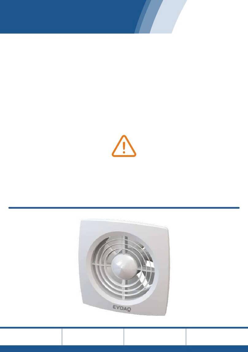
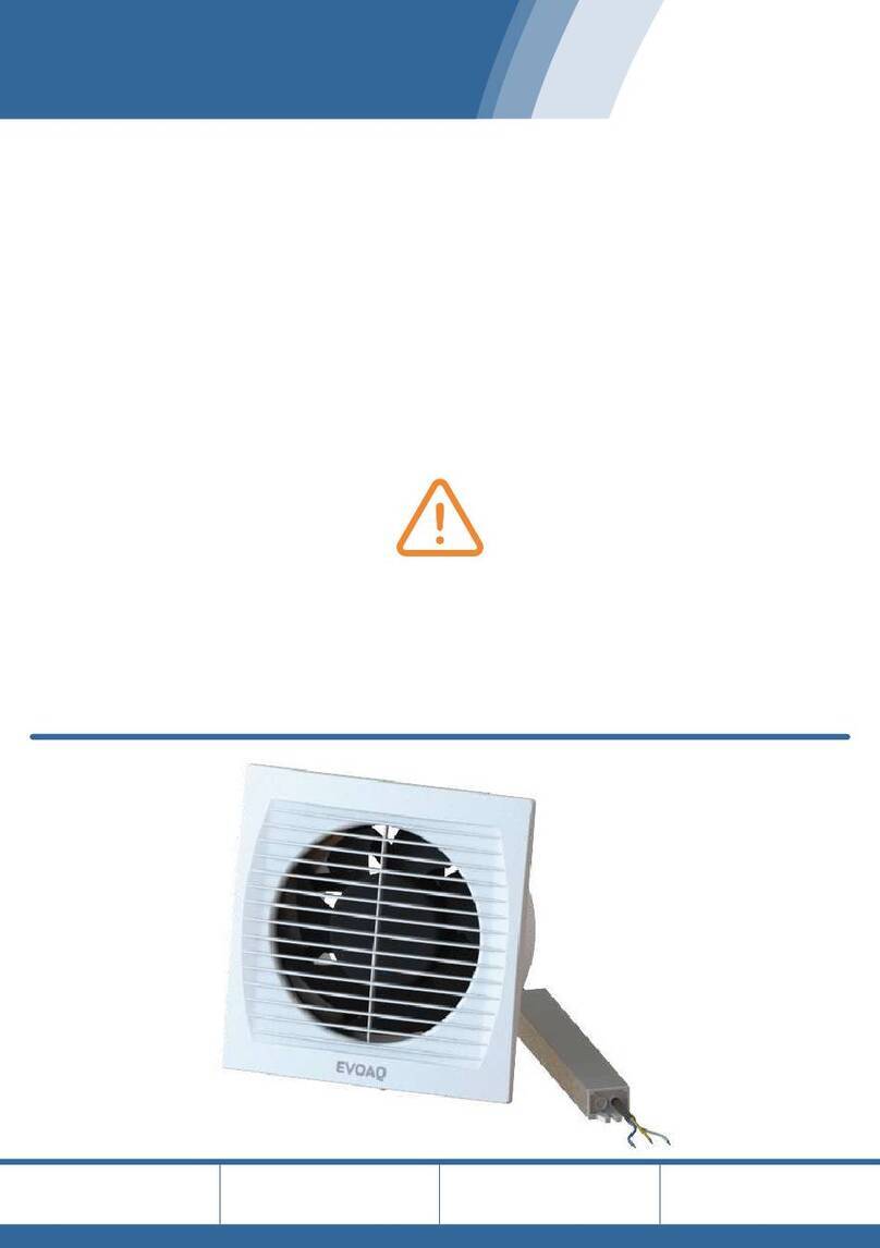
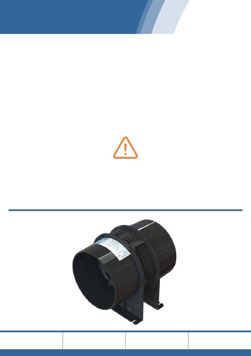
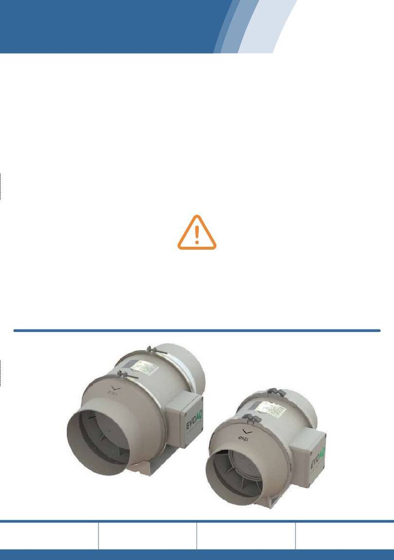
EVOAQ EX-AX150MC User manual

Fan Installation Manual
Please take the time to read these instructions in full before
commencing your installation.
Careful planning prior to starting work will guarantee the
fastest and best results regarding the installation.
Working in the ceiling space can be a hazard, and all
safety precautions should be used to ensure the
safety of yourself and any others.
EVOAQ
Air Quality Innovation
Bathroom Extraction
Fan Model
EX-AX150MC
Software Version
V1.1
Manual Version
V3.3.0 09-2023
Adjustable Speed
Extraction

Installation Manual
150mm EC Axial Fan for Manual Extraction (Adjustable Speed)
Thank you for your purchase of our company’s product. It has been manufactured following
current technical safety regulations and is in compliance with AS/NZ60335 standard.
Please read this instruction booklet carefully before installing or starting up the
product.
It contains important information on personal and user safety measures to be followed while
installing, using, and carrying out maintenance work on the equipment. Once the product
has been installed, please hand this booklet to the end user.
Before installing the fan, it is important to understand the way this fan functions.
The fan is designed to be continuously powered.
While there is no signal on the switch wire the fan runs in standby mode at its lowest speed
(trickle speed).
When the fan detects a signal on the switch wire for at least 5 seconds, it will start to slowly
ramp up. It will continue to ramp up while there is a signal on the switch, until the switch is
released, or until the fan reaches full speed.
If the switch is released within 30s of being activated, the fan will then ramp down again to
trickle speed. If the switch is released after more than 30s, the fan continues running at its
current speed for 7 minutes before slowing down again to trickle speed in standby mode.
This model fan does include the option of adding a remote switch input - refer to
fan wiring on page 5 for details.
INSTALLATION OVERVIEW
Before commencing installation, select a suitable place for the fan to be installed in the
ceiling cavity. The fan will be placed centrally within the ducted system, but should be no
more than 2 metres away from the inlet grille. For maximum effectiveness of the fan, do not
use more than 6m total length of ducting between the inlet and outlet.
It is recommended to suspend your fan from the ceiling framing with the chain provided in
order to minimise the sound levels resonating through the ceiling framing. Do not screw the
fan directly onto the timber frame!
Cut the hole for the inside grille and pull one end of the ducting through. Attach the spigot
of the inside grille to the end of the flexible duct with the duct tape provided. Pull the ducting
out to the fan, cut it to the desired length, and tape it onto the fan inlet.
Attach the remaining ducting to the fan outlet and feed the other end through the exterior
grille hole. Ensure the ducting is long enough to tape onto the spigot of the outside grille.
Cut off excess ducting and tape the end to the grille. Push the grille into place and fasten to
the wall/soffit.
Please note:
The inlet of the fan unit is on the side of the fan blades, the side that is not obstructed by
the fan frame. There are also arrows on the unit and rating label showing airflow direction.
Excessive ducting and sharp bends lower the fan’s performance. Before cutting the ducting,
ensure the duct is long enough, with gradual bends.
Important information for the safety of installers and user:
Installation must only be carried out by qualified persons. Make sure that the installation
complies with the applicable building and electrical regulations.
This appliance is not intended for use by young children or infirm persons unless they have
been adequately supervised by a responsible person to ensure that they can use the
appliance safely. Young children should be supervised to ensure that they do not play with
the appliance.
This apparatus must not be used in explosive or corrosive atmospheres. If a fan is going to
be installed to extract air from premises where a boiler or other combustion apparatus are
installed, make sure that the building has sufficient air intakes to assure adequate
combustion. The extractor outlet must not be connected to a duct used to exhaust smoke or
fumes from any appliance that uses gas or any other type of fuel.
TRANSPORT AND MANIPULATION
The packaging used for this apparatus has been designed to support normal transporting
conditions. The apparatus must always be transported in its original packaging as not doing
so could deform or damage the product. Do not place heavy weights on the packed product
and avoid knocking or dropping it.
The product should be stored in a dry place in its original packaging, protected from dust
and dirt until it is installed in its final location. Do not accept delivery if the apparatus is not
in its original packaging or shows clear signs of having been manipulated in any way.
Check that the apparatus is in perfect condition while unpacking. Any fault or damage
caused in origin is covered by our company guarantee. Please make sure that the apparatus
coincides with the product you have ordered and that the details on the rating label fulfil
your requirements.
ELECTRICAL CONNECTION
The extractor fan must be connected to a single-phase mains network, with the specific
voltage and frequency according to the specifications on the fan rating label and in
accordance with New Zealand electrical standards.
If the fan model you have purchased is fitted with a power plug then please note removing
this plug will void the warranty of the fan.
In case of damage to the power plug, cord, or device itself, switch off the device and do not
tamper with it. Damaged product must only be repaired or replaced exclusively by the
manufacturer or by an appointed representative. Failure to comply with the above may
endanger the safety of people and cause possible damage to the whole system.
SAFETY DURING INSTALLATION
Make sure there are no loose elements near the fan, as they could run the risk of being
sucked up by it. If it is going to be installed in a duct, check that it is clean of any element
that could be sucked up by the fan. When installing an apparatus, make sure that all the
fittings are in place and that the structure which supports it is resistant enough to bear its
weight at full functioning power.
Before installing the fan, make sure the mains supply is disconnected, even if the fan is
switched off.
If the fan is installed in a duct, the duct must be used for the extraction system only.
STARTING UP THE FAN
Fans may have delayed startup, or may operate under the control of the inbuilt controlling
electronics included with the fan. Always take extreme care as the fan may start unexpect-
edly. Always disconnect the fan from power during maintenance.
Before starting up the fan, ensure that:
•
•
•
•
When starting up the fan, ensure that:
•
•
If the circuit protection device is tripping during operation, the apparatus must be quickly
disconnected from the mains supply. The whole installation should be carefully checked
before trying to start up the machine again.
MAINTENANCE AND REPAIR
Before servicing the fan, make sure it is disconnected from the mains supply - even if it has
previously been switched off. Avoid the risk of anyone else plugging it in while you’re
working on it.
The fan must be regularly inspected. These inspections should consider the fan’s working
conditions, ensuring no dirt or dust builds up on the propeller, turbine, motor or grilles. This
could be dangerous and perceptibly shorten the fan’s lifespan. While cleaning, take extra
care not to damage the propeller.
All maintenance work should be carried out in strict compliance with New Zealand safety
regulations.
All our products contain repairable or replaceable parts. Repair or replacement of these parts
should only be handled by the manufacturer. In the case of damage or malfunction of the
fan, please contact the manufacturer or installer to arrange for repair. Please note that a
small fee may apply for repair services not covered under warranty.
FAN MOUNTING
SYSTEM INSTALLATION
FAN WIRING
This fan includes two sets of cables/wires: the power lead and the external switch. Please
refer to the images below to ensure the fan is wired correctly to prevent damaging the fan.
Power lead - Fan is fitted with plug; do not cut off plug unless necessary:
Blue = Neutral
Brown = Phase (Live)
Yellow/Green = Earth -> This product is double-insulated and not earthed, earth wire does
not need to be connected
External switch - Dry contact (requires latching switch):
White = Switch Signal (0-5V)
Black Stripe = Common (0V)
Switch functionality:
Short press (5 - 30s): Fan speeds up while switch is being pressed, then gradually slows
down again to trickle speed after switch is released.
Long press (over 30s): Fan speeds up while switch is on. When the switch is released again
it will continue running at its current speed for 7 minutes before slowing down to trickle
speed again.
Refer to page 6 for instructions on how to wire the EVOAQ 230VAC isolation switch add-on
for interfacing with mains voltage signals (e.g. light switch).
ISOLATION SWITCH WIRING
If required, the switch input wire to the fan can be interconnected with a mains signal such
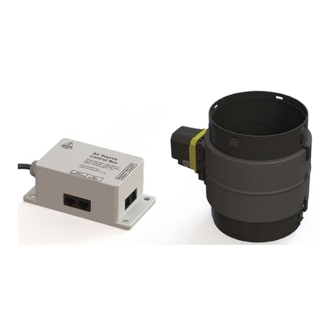
as a bathroom light or PIR sensor. This can be done by wiring in our isolation switch box
between the fan and the mains signal.
The isolation switch box is connected to the fan via a 2-core cable. This cable is the low-volt-
age signal cable, with up to 5V on it and should not be connected directly to 230VAC
(mains voltage) under any circumstances.
The other cable included with the isolation switch box is 230VAC rated, and should be used
to interface the fan with a 230VAC boost switch or light switch.
Wiring of the isolation switch box is recommended to only be carried out by a qualified
electrician and in accordance with the relevant electrical standards.
For further information, please contact EvolutionFX NZ Limited
email: info@evolutionfx.co.nz
phone: +64 9 558 5590
EVOAQ
Air Quality Innovation
EVOAQ Bathroom Extraction
Page 2 www.evoaq.co.nz

Installation Manual
150mm EC Axial Fan for Manual Extraction (Adjustable Speed)
Thank you for your purchase of our company’s product. It has been manufactured following
current technical safety regulations and is in compliance with AS/NZ60335 standard.
Please read this instruction booklet carefully before installing or starting up the
product.
It contains important information on personal and user safety measures to be followed while
installing, using, and carrying out maintenance work on the equipment. Once the product
has been installed, please hand this booklet to the end user.
Before installing the fan, it is important to understand the way this fan functions.
The fan is designed to be continuously powered.
While there is no signal on the switch wire the fan runs in standby mode at its lowest speed
(trickle speed).
When the fan detects a signal on the switch wire for at least 5 seconds, it will start to slowly
ramp up. It will continue to ramp up while there is a signal on the switch, until the switch is
released, or until the fan reaches full speed.
If the switch is released within 30s of being activated, the fan will then ramp down again to
trickle speed. If the switch is released after more than 30s, the fan continues running at its
current speed for 7 minutes before slowing down again to trickle speed in standby mode.
This model fan does include the option of adding a remote switch input - refer to
fan wiring on page 5 for details.
INSTALLATION OVERVIEW
Before commencing installation, select a suitable place for the fan to be installed in the
ceiling cavity. The fan will be placed centrally within the ducted system, but should be no
more than 2 metres away from the inlet grille. For maximum effectiveness of the fan, do not
use more than 6m total length of ducting between the inlet and outlet.
It is recommended to suspend your fan from the ceiling framing with the chain provided in
order to minimise the sound levels resonating through the ceiling framing. Do not screw the
fan directly onto the timber frame!
Cut the hole for the inside grille and pull one end of the ducting through. Attach the spigot
of the inside grille to the end of the flexible duct with the duct tape provided. Pull the ducting
out to the fan, cut it to the desired length, and tape it onto the fan inlet.
Attach the remaining ducting to the fan outlet and feed the other end through the exterior
grille hole. Ensure the ducting is long enough to tape onto the spigot of the outside grille.
Cut off excess ducting and tape the end to the grille. Push the grille into place and fasten to
the wall/soffit.
Please note:
The inlet of the fan unit is on the side of the fan blades, the side that is not obstructed by
the fan frame. There are also arrows on the unit and rating label showing airflow direction.
Excessive ducting and sharp bends lower the fan’s performance. Before cutting the ducting,
ensure the duct is long enough, with gradual bends.
Important information for the safety of installers and user:
Installation must only be carried out by qualified persons. Make sure that the installation
complies with the applicable building and electrical regulations.
This appliance is not intended for use by young children or infirm persons unless they have
been adequately supervised by a responsible person to ensure that they can use the
appliance safely. Young children should be supervised to ensure that they do not play with
the appliance.
This apparatus must not be used in explosive or corrosive atmospheres. If a fan is going to
be installed to extract air from premises where a boiler or other combustion apparatus are
installed, make sure that the building has sufficient air intakes to assure adequate
combustion. The extractor outlet must not be connected to a duct used to exhaust smoke or
fumes from any appliance that uses gas or any other type of fuel.
TRANSPORT AND MANIPULATION
The packaging used for this apparatus has been designed to support normal transporting
conditions. The apparatus must always be transported in its original packaging as not doing
so could deform or damage the product. Do not place heavy weights on the packed product
and avoid knocking or dropping it.
The product should be stored in a dry place in its original packaging, protected from dust
and dirt until it is installed in its final location. Do not accept delivery if the apparatus is not
in its original packaging or shows clear signs of having been manipulated in any way.
Check that the apparatus is in perfect condition while unpacking. Any fault or damage
caused in origin is covered by our company guarantee. Please make sure that the apparatus
coincides with the product you have ordered and that the details on the rating label fulfil
your requirements.
ELECTRICAL CONNECTION
The extractor fan must be connected to a single-phase mains network, with the specific
voltage and frequency according to the specifications on the fan rating label and in
accordance with New Zealand electrical standards.
If the fan model you have purchased is fitted with a power plug then please note removing
this plug will void the warranty of the fan.
In case of damage to the power plug, cord, or device itself, switch off the device and do not
tamper with it. Damaged product must only be repaired or replaced exclusively by the
manufacturer or by an appointed representative. Failure to comply with the above may
endanger the safety of people and cause possible damage to the whole system.
SAFETY DURING INSTALLATION
Make sure there are no loose elements near the fan, as they could run the risk of being
sucked up by it. If it is going to be installed in a duct, check that it is clean of any element
that could be sucked up by the fan. When installing an apparatus, make sure that all the
fittings are in place and that the structure which supports it is resistant enough to bear its
weight at full functioning power.
Before installing the fan, make sure the mains supply is disconnected, even if the fan is
switched off.
If the fan is installed in a duct, the duct must be used for the extraction system only.
STARTING UP THE FAN
Fans may have delayed startup, or may operate under the control of the inbuilt controlling
electronics included with the fan. Always take extreme care as the fan may start unexpect-
edly. Always disconnect the fan from power during maintenance.
Before starting up the fan, ensure that:
•
•
•
•
When starting up the fan, ensure that:
•
•
If the circuit protection device is tripping during operation, the apparatus must be quickly
disconnected from the mains supply. The whole installation should be carefully checked
before trying to start up the machine again.
MAINTENANCE AND REPAIR
Before servicing the fan, make sure it is disconnected from the mains supply - even if it has
previously been switched off. Avoid the risk of anyone else plugging it in while you’re
working on it.
The fan must be regularly inspected. These inspections should consider the fan’s working
conditions, ensuring no dirt or dust builds up on the propeller, turbine, motor or grilles. This
could be dangerous and perceptibly shorten the fan’s lifespan. While cleaning, take extra
care not to damage the propeller.
All maintenance work should be carried out in strict compliance with New Zealand safety
regulations.
All our products contain repairable or replaceable parts. Repair or replacement of these parts
should only be handled by the manufacturer. In the case of damage or malfunction of the
fan, please contact the manufacturer or installer to arrange for repair. Please note that a
small fee may apply for repair services not covered under warranty.
FAN MOUNTING
SYSTEM INSTALLATION
FAN WIRING
This fan includes two sets of cables/wires: the power lead and the external switch. Please
refer to the images below to ensure the fan is wired correctly to prevent damaging the fan.
Power lead - Fan is fitted with plug; do not cut off plug unless necessary:
Blue = Neutral
Brown = Phase (Live)
Yellow/Green = Earth -> This product is double-insulated and not earthed, earth wire does
not need to be connected
External switch - Dry contact (requires latching switch):
White = Switch Signal (0-5V)
Black Stripe = Common (0V)
Switch functionality:
Short press (5 - 30s): Fan speeds up while switch is being pressed, then gradually slows
down again to trickle speed after switch is released.
Long press (over 30s): Fan speeds up while switch is on. When the switch is released again
it will continue running at its current speed for 7 minutes before slowing down to trickle
speed again.
Refer to page 6 for instructions on how to wire the EVOAQ 230VAC isolation switch add-on
for interfacing with mains voltage signals (e.g. light switch).
ISOLATION SWITCH WIRING
If required, the switch input wire to the fan can be interconnected with a mains signal such
as a bathroom light or PIR sensor. This can be done by wiring in our isolation switch box
between the fan and the mains signal.
The isolation switch box is connected to the fan via a 2-core cable. This cable is the low-volt-
age signal cable, with up to 5V on it and should not be connected directly to 230VAC
(mains voltage) under any circumstances.
The other cable included with the isolation switch box is 230VAC rated, and should be used
to interface the fan with a 230VAC boost switch or light switch.
Wiring of the isolation switch box is recommended to only be carried out by a qualified
electrician and in accordance with the relevant electrical standards.
For further information, please contact EvolutionFX NZ Limited
email: info@evolutionfx.co.nz
phone: +64 9 558 5590
EVOAQ
Air Quality Innovation
EVOAQ Bathroom Extraction
Page 3www.evoaq.co.nz

Installation Manual
150mm EC Axial Fan for Manual Extraction (Adjustable Speed)
Thank you for your purchase of our company’s product. It has been manufactured following
current technical safety regulations and is in compliance with AS/NZ60335 standard.
Please read this instruction booklet carefully before installing or starting up the
product.
It contains important information on personal and user safety measures to be followed while
installing, using, and carrying out maintenance work on the equipment. Once the product
has been installed, please hand this booklet to the end user.
Before installing the fan, it is important to understand the way this fan functions.
The fan is designed to be continuously powered.
While there is no signal on the switch wire the fan runs in standby mode at its lowest speed
(trickle speed).
When the fan detects a signal on the switch wire for at least 5 seconds, it will start to slowly
ramp up. It will continue to ramp up while there is a signal on the switch, until the switch is
released, or until the fan reaches full speed.
If the switch is released within 30s of being activated, the fan will then ramp down again to
trickle speed. If the switch is released after more than 30s, the fan continues running at its
current speed for 7 minutes before slowing down again to trickle speed in standby mode.
This model fan does include the option of adding a remote switch input - refer to
fan wiring on page 5 for details.
INSTALLATION OVERVIEW
Before commencing installation, select a suitable place for the fan to be installed in the
ceiling cavity. The fan will be placed centrally within the ducted system, but should be no
more than 2 metres away from the inlet grille. For maximum effectiveness of the fan, do not
use more than 6m total length of ducting between the inlet and outlet.
It is recommended to suspend your fan from the ceiling framing with the chain provided in
order to minimise the sound levels resonating through the ceiling framing. Do not screw the
fan directly onto the timber frame!
Cut the hole for the inside grille and pull one end of the ducting through. Attach the spigot
of the inside grille to the end of the flexible duct with the duct tape provided. Pull the ducting
out to the fan, cut it to the desired length, and tape it onto the fan inlet.
Attach the remaining ducting to the fan outlet and feed the other end through the exterior
grille hole. Ensure the ducting is long enough to tape onto the spigot of the outside grille.
Cut off excess ducting and tape the end to the grille. Push the grille into place and fasten to
the wall/soffit.
Please note:
The inlet of the fan unit is on the side of the fan blades, the side that is not obstructed by
the fan frame. There are also arrows on the unit and rating label showing airflow direction.
Excessive ducting and sharp bends lower the fan’s performance. Before cutting the ducting,
ensure the duct is long enough, with gradual bends.
Important information for the safety of installers and user:
Installation must only be carried out by qualified persons. Make sure that the installation
complies with the applicable building and electrical regulations.
This appliance is not intended for use by young children or infirm persons unless they have
been adequately supervised by a responsible person to ensure that they can use the
appliance safely. Young children should be supervised to ensure that they do not play with
the appliance.
This apparatus must not be used in explosive or corrosive atmospheres. If a fan is going to
be installed to extract air from premises where a boiler or other combustion apparatus are
installed, make sure that the building has sufficient air intakes to assure adequate
combustion. The extractor outlet must not be connected to a duct used to exhaust smoke or
fumes from any appliance that uses gas or any other type of fuel.
TRANSPORT AND MANIPULATION
The packaging used for this apparatus has been designed to support normal transporting
conditions. The apparatus must always be transported in its original packaging as not doing
so could deform or damage the product. Do not place heavy weights on the packed product
and avoid knocking or dropping it.
The product should be stored in a dry place in its original packaging, protected from dust
and dirt until it is installed in its final location. Do not accept delivery if the apparatus is not
in its original packaging or shows clear signs of having been manipulated in any way.
Check that the apparatus is in perfect condition while unpacking. Any fault or damage
caused in origin is covered by our company guarantee. Please make sure that the apparatus
coincides with the product you have ordered and that the details on the rating label fulfil
your requirements.
ELECTRICAL CONNECTION
The extractor fan must be connected to a single-phase mains network, with the specific
voltage and frequency according to the specifications on the fan rating label and in
accordance with New Zealand electrical standards.
If the fan model you have purchased is fitted with a power plug then please note removing
this plug will void the warranty of the fan.
In case of damage to the power plug, cord, or device itself, switch off the device and do not
tamper with it. Damaged product must only be repaired or replaced exclusively by the
manufacturer or by an appointed representative. Failure to comply with the above may
endanger the safety of people and cause possible damage to the whole system.
SAFETY DURING INSTALLATION
Make sure there are no loose elements near the fan, as they could run the risk of being
sucked up by it. If it is going to be installed in a duct, check that it is clean of any element
that could be sucked up by the fan. When installing an apparatus, make sure that all the
fittings are in place and that the structure which supports it is resistant enough to bear its
weight at full functioning power.
Before installing the fan, make sure the mains supply is disconnected, even if the fan is
switched off.
If the fan is installed in a duct, the duct must be used for the extraction system only.
STARTING UP THE FAN
Fans may have delayed startup, or may operate under the control of the inbuilt controlling
electronics included with the fan. Always take extreme care as the fan may start unexpect-
edly. Always disconnect the fan from power during maintenance.
Before starting up the fan, ensure that:
•
•
•
•
When starting up the fan, ensure that:
•
•
If the circuit protection device is tripping during operation, the apparatus must be quickly
disconnected from the mains supply. The whole installation should be carefully checked
before trying to start up the machine again.
MAINTENANCE AND REPAIR
Before servicing the fan, make sure it is disconnected from the mains supply - even if it has
previously been switched off. Avoid the risk of anyone else plugging it in while you’re
working on it.
The fan must be regularly inspected. These inspections should consider the fan’s working
conditions, ensuring no dirt or dust builds up on the propeller, turbine, motor or grilles. This
could be dangerous and perceptibly shorten the fan’s lifespan. While cleaning, take extra
care not to damage the propeller.
All maintenance work should be carried out in strict compliance with New Zealand safety
regulations.
All our products contain repairable or replaceable parts. Repair or replacement of these parts
should only be handled by the manufacturer. In the case of damage or malfunction of the
fan, please contact the manufacturer or installer to arrange for repair. Please note that a
small fee may apply for repair services not covered under warranty.
FAN MOUNTING
SYSTEM INSTALLATION
FAN WIRING
This fan includes two sets of cables/wires: the power lead and the external switch. Please
refer to the images below to ensure the fan is wired correctly to prevent damaging the fan.
Power lead - Fan is fitted with plug; do not cut off plug unless necessary:
Blue = Neutral
Brown = Phase (Live)
Yellow/Green = Earth -> This product is double-insulated and not earthed, earth wire does
not need to be connected
External switch - Dry contact (requires latching switch):
White = Switch Signal (0-5V)
Black Stripe = Common (0V)
Switch functionality:
Short press (5 - 30s): Fan speeds up while switch is being pressed, then gradually slows
down again to trickle speed after switch is released.
Long press (over 30s): Fan speeds up while switch is on. When the switch is released again
it will continue running at its current speed for 7 minutes before slowing down to trickle
speed again.
Refer to page 6 for instructions on how to wire the EVOAQ 230VAC isolation switch add-on
for interfacing with mains voltage signals (e.g. light switch).
ISOLATION SWITCH WIRING
If required, the switch input wire to the fan can be interconnected with a mains signal such
as a bathroom light or PIR sensor. This can be done by wiring in our isolation switch box
between the fan and the mains signal.
The isolation switch box is connected to the fan via a 2-core cable. This cable is the low-volt-
age signal cable, with up to 5V on it and should not be connected directly to 230VAC
(mains voltage) under any circumstances.
The other cable included with the isolation switch box is 230VAC rated, and should be used
to interface the fan with a 230VAC boost switch or light switch.
Wiring of the isolation switch box is recommended to only be carried out by a qualified
electrician and in accordance with the relevant electrical standards.
For further information, please contact EvolutionFX NZ Limited
email: info@evolutionfx.co.nz
phone: +64 9 558 5590
EVOAQ extraction fan - outlet sideSuspend the fan with chain
EVOAQ
Air Quality Innovation
EVOAQ Bathroom Extraction
The fan is well secured and the electrical connections have been carried out correctly;
Any electrical safety devices are correctly connected, adequately adjusted and ready for
use;
The wire and electrical connection inputs are correctly sealed and water-tight;
If the fan has been mounted in a duct, the duct is clear of any loose material that could
be sucked up by the fan.
The propeller turns in the correct direction;
There are no abnormal vibrations.
Page 4 www.evoaq.co.nz

Installation Manual
150mm EC Axial Fan for Manual Extraction (Adjustable Speed)
Thank you for your purchase of our company’s product. It has been manufactured following
current technical safety regulations and is in compliance with AS/NZ60335 standard.
Please read this instruction booklet carefully before installing or starting up the
product.
It contains important information on personal and user safety measures to be followed while
installing, using, and carrying out maintenance work on the equipment. Once the product
has been installed, please hand this booklet to the end user.
Before installing the fan, it is important to understand the way this fan functions.
The fan is designed to be continuously powered.
While there is no signal on the switch wire the fan runs in standby mode at its lowest speed
(trickle speed).
When the fan detects a signal on the switch wire for at least 5 seconds, it will start to slowly
ramp up. It will continue to ramp up while there is a signal on the switch, until the switch is
released, or until the fan reaches full speed.
If the switch is released within 30s of being activated, the fan will then ramp down again to
trickle speed. If the switch is released after more than 30s, the fan continues running at its
current speed for 7 minutes before slowing down again to trickle speed in standby mode.
This model fan does include the option of adding a remote switch input - refer to
fan wiring on page 5 for details.
INSTALLATION OVERVIEW
Before commencing installation, select a suitable place for the fan to be installed in the
ceiling cavity. The fan will be placed centrally within the ducted system, but should be no
more than 2 metres away from the inlet grille. For maximum effectiveness of the fan, do not
use more than 6m total length of ducting between the inlet and outlet.
It is recommended to suspend your fan from the ceiling framing with the chain provided in
order to minimise the sound levels resonating through the ceiling framing. Do not screw the
fan directly onto the timber frame!
Cut the hole for the inside grille and pull one end of the ducting through. Attach the spigot
of the inside grille to the end of the flexible duct with the duct tape provided. Pull the ducting
out to the fan, cut it to the desired length, and tape it onto the fan inlet.
Attach the remaining ducting to the fan outlet and feed the other end through the exterior
grille hole. Ensure the ducting is long enough to tape onto the spigot of the outside grille.
Cut off excess ducting and tape the end to the grille. Push the grille into place and fasten to
the wall/soffit.
Please note:
The inlet of the fan unit is on the side of the fan blades, the side that is not obstructed by
the fan frame. There are also arrows on the unit and rating label showing airflow direction.
Excessive ducting and sharp bends lower the fan’s performance. Before cutting the ducting,
ensure the duct is long enough, with gradual bends.
Important information for the safety of installers and user:
Installation must only be carried out by qualified persons. Make sure that the installation
complies with the applicable building and electrical regulations.
This appliance is not intended for use by young children or infirm persons unless they have
been adequately supervised by a responsible person to ensure that they can use the
appliance safely. Young children should be supervised to ensure that they do not play with
the appliance.
This apparatus must not be used in explosive or corrosive atmospheres. If a fan is going to
be installed to extract air from premises where a boiler or other combustion apparatus are
installed, make sure that the building has sufficient air intakes to assure adequate
combustion. The extractor outlet must not be connected to a duct used to exhaust smoke or
fumes from any appliance that uses gas or any other type of fuel.
TRANSPORT AND MANIPULATION
The packaging used for this apparatus has been designed to support normal transporting
conditions. The apparatus must always be transported in its original packaging as not doing
so could deform or damage the product. Do not place heavy weights on the packed product
and avoid knocking or dropping it.
The product should be stored in a dry place in its original packaging, protected from dust
and dirt until it is installed in its final location. Do not accept delivery if the apparatus is not
in its original packaging or shows clear signs of having been manipulated in any way.
Check that the apparatus is in perfect condition while unpacking. Any fault or damage
caused in origin is covered by our company guarantee. Please make sure that the apparatus
coincides with the product you have ordered and that the details on the rating label fulfil
your requirements.
ELECTRICAL CONNECTION
The extractor fan must be connected to a single-phase mains network, with the specific
voltage and frequency according to the specifications on the fan rating label and in
accordance with New Zealand electrical standards.
If the fan model you have purchased is fitted with a power plug then please note removing
this plug will void the warranty of the fan.
In case of damage to the power plug, cord, or device itself, switch off the device and do not
tamper with it. Damaged product must only be repaired or replaced exclusively by the
manufacturer or by an appointed representative. Failure to comply with the above may
endanger the safety of people and cause possible damage to the whole system.
SAFETY DURING INSTALLATION
Make sure there are no loose elements near the fan, as they could run the risk of being
sucked up by it. If it is going to be installed in a duct, check that it is clean of any element
that could be sucked up by the fan. When installing an apparatus, make sure that all the
fittings are in place and that the structure which supports it is resistant enough to bear its
weight at full functioning power.
Before installing the fan, make sure the mains supply is disconnected, even if the fan is
switched off.
If the fan is installed in a duct, the duct must be used for the extraction system only.
STARTING UP THE FAN
Fans may have delayed startup, or may operate under the control of the inbuilt controlling
electronics included with the fan. Always take extreme care as the fan may start unexpect-
edly. Always disconnect the fan from power during maintenance.
Before starting up the fan, ensure that:
•
•
•
•
When starting up the fan, ensure that:
•
•
If the circuit protection device is tripping during operation, the apparatus must be quickly
disconnected from the mains supply. The whole installation should be carefully checked
before trying to start up the machine again.
MAINTENANCE AND REPAIR
Before servicing the fan, make sure it is disconnected from the mains supply - even if it has
previously been switched off. Avoid the risk of anyone else plugging it in while you’re
working on it.
The fan must be regularly inspected. These inspections should consider the fan’s working
conditions, ensuring no dirt or dust builds up on the propeller, turbine, motor or grilles. This
could be dangerous and perceptibly shorten the fan’s lifespan. While cleaning, take extra
care not to damage the propeller.
All maintenance work should be carried out in strict compliance with New Zealand safety
regulations.
All our products contain repairable or replaceable parts. Repair or replacement of these parts
should only be handled by the manufacturer. In the case of damage or malfunction of the
fan, please contact the manufacturer or installer to arrange for repair. Please note that a
small fee may apply for repair services not covered under warranty.
FAN MOUNTING
SYSTEM INSTALLATION
FAN WIRING
This fan includes two sets of cables/wires: the power lead and the external switch. Please
refer to the images below to ensure the fan is wired correctly to prevent damaging the fan.
Power lead - Fan is fitted with plug; do not cut off plug unless necessary:
Blue = Neutral
Brown = Phase (Live)
Yellow/Green = Earth -> This product is double-insulated and not earthed, earth wire does
not need to be connected
External switch - Dry contact (requires latching switch):
White = Switch Signal (0-5V)
Black Stripe = Common (0V)
Switch functionality:
Short press (5 - 30s): Fan speeds up while switch is being pressed, then gradually slows
down again to trickle speed after switch is released.
Long press (over 30s): Fan speeds up while switch is on. When the switch is released again
it will continue running at its current speed for 7 minutes before slowing down to trickle
speed again.
Refer to page 6 for instructions on how to wire the EVOAQ 230VAC isolation switch add-on
for interfacing with mains voltage signals (e.g. light switch).
ISOLATION SWITCH WIRING
If required, the switch input wire to the fan can be interconnected with a mains signal such
as a bathroom light or PIR sensor. This can be done by wiring in our isolation switch box
between the fan and the mains signal.
The isolation switch box is connected to the fan via a 2-core cable. This cable is the low-volt-
age signal cable, with up to 5V on it and should not be connected directly to 230VAC
(mains voltage) under any circumstances.
The other cable included with the isolation switch box is 230VAC rated, and should be used
to interface the fan with a 230VAC boost switch or light switch.
Wiring of the isolation switch box is recommended to only be carried out by a qualified
electrician and in accordance with the relevant electrical standards.
For further information, please contact EvolutionFX NZ Limited
email: info@evolutionfx.co.nz
phone: +64 9 558 5590
EVOAQ
Air Quality Innovation
EVOAQ Bathroom Extraction
SIGNAL
0V
N
L
+
Page 5www.evoaq.co.nz

Installation Manual
150mm EC Axial Fan for Manual Extraction (Adjustable Speed)
Thank you for your purchase of our company’s product. It has been manufactured following
current technical safety regulations and is in compliance with AS/NZ60335 standard.
Please read this instruction booklet carefully before installing or starting up the
product.
It contains important information on personal and user safety measures to be followed while
installing, using, and carrying out maintenance work on the equipment. Once the product
has been installed, please hand this booklet to the end user.
Before installing the fan, it is important to understand the way this fan functions.
The fan is designed to be continuously powered.
While there is no signal on the switch wire the fan runs in standby mode at its lowest speed
(trickle speed).
When the fan detects a signal on the switch wire for at least 5 seconds, it will start to slowly
ramp up. It will continue to ramp up while there is a signal on the switch, until the switch is
released, or until the fan reaches full speed.
If the switch is released within 30s of being activated, the fan will then ramp down again to
trickle speed. If the switch is released after more than 30s, the fan continues running at its
current speed for 7 minutes before slowing down again to trickle speed in standby mode.
This model fan does include the option of adding a remote switch input - refer to
fan wiring on page 5 for details.
INSTALLATION OVERVIEW
Before commencing installation, select a suitable place for the fan to be installed in the
ceiling cavity. The fan will be placed centrally within the ducted system, but should be no
more than 2 metres away from the inlet grille. For maximum effectiveness of the fan, do not
use more than 6m total length of ducting between the inlet and outlet.
It is recommended to suspend your fan from the ceiling framing with the chain provided in
order to minimise the sound levels resonating through the ceiling framing. Do not screw the
fan directly onto the timber frame!
Cut the hole for the inside grille and pull one end of the ducting through. Attach the spigot
of the inside grille to the end of the flexible duct with the duct tape provided. Pull the ducting
out to the fan, cut it to the desired length, and tape it onto the fan inlet.
Attach the remaining ducting to the fan outlet and feed the other end through the exterior
grille hole. Ensure the ducting is long enough to tape onto the spigot of the outside grille.
Cut off excess ducting and tape the end to the grille. Push the grille into place and fasten to
the wall/soffit.
Please note:
The inlet of the fan unit is on the side of the fan blades, the side that is not obstructed by
the fan frame. There are also arrows on the unit and rating label showing airflow direction.
Excessive ducting and sharp bends lower the fan’s performance. Before cutting the ducting,
ensure the duct is long enough, with gradual bends.
Important information for the safety of installers and user:
Installation must only be carried out by qualified persons. Make sure that the installation
complies with the applicable building and electrical regulations.
This appliance is not intended for use by young children or infirm persons unless they have
been adequately supervised by a responsible person to ensure that they can use the
appliance safely. Young children should be supervised to ensure that they do not play with
the appliance.
This apparatus must not be used in explosive or corrosive atmospheres. If a fan is going to
be installed to extract air from premises where a boiler or other combustion apparatus are
installed, make sure that the building has sufficient air intakes to assure adequate
combustion. The extractor outlet must not be connected to a duct used to exhaust smoke or
fumes from any appliance that uses gas or any other type of fuel.
TRANSPORT AND MANIPULATION
The packaging used for this apparatus has been designed to support normal transporting
conditions. The apparatus must always be transported in its original packaging as not doing
so could deform or damage the product. Do not place heavy weights on the packed product
and avoid knocking or dropping it.
The product should be stored in a dry place in its original packaging, protected from dust
and dirt until it is installed in its final location. Do not accept delivery if the apparatus is not
in its original packaging or shows clear signs of having been manipulated in any way.
Check that the apparatus is in perfect condition while unpacking. Any fault or damage
caused in origin is covered by our company guarantee. Please make sure that the apparatus
coincides with the product you have ordered and that the details on the rating label fulfil
your requirements.
ELECTRICAL CONNECTION
The extractor fan must be connected to a single-phase mains network, with the specific
voltage and frequency according to the specifications on the fan rating label and in
accordance with New Zealand electrical standards.
If the fan model you have purchased is fitted with a power plug then please note removing
this plug will void the warranty of the fan.
In case of damage to the power plug, cord, or device itself, switch off the device and do not
tamper with it. Damaged product must only be repaired or replaced exclusively by the
manufacturer or by an appointed representative. Failure to comply with the above may
endanger the safety of people and cause possible damage to the whole system.
SAFETY DURING INSTALLATION
Make sure there are no loose elements near the fan, as they could run the risk of being
sucked up by it. If it is going to be installed in a duct, check that it is clean of any element
that could be sucked up by the fan. When installing an apparatus, make sure that all the
fittings are in place and that the structure which supports it is resistant enough to bear its
weight at full functioning power.
Before installing the fan, make sure the mains supply is disconnected, even if the fan is
switched off.
If the fan is installed in a duct, the duct must be used for the extraction system only.
STARTING UP THE FAN
Fans may have delayed startup, or may operate under the control of the inbuilt controlling
electronics included with the fan. Always take extreme care as the fan may start unexpect-
edly. Always disconnect the fan from power during maintenance.
Before starting up the fan, ensure that:
•
•
•
•
When starting up the fan, ensure that:
•
•
If the circuit protection device is tripping during operation, the apparatus must be quickly
disconnected from the mains supply. The whole installation should be carefully checked
before trying to start up the machine again.
MAINTENANCE AND REPAIR
Before servicing the fan, make sure it is disconnected from the mains supply - even if it has
previously been switched off. Avoid the risk of anyone else plugging it in while you’re
working on it.
The fan must be regularly inspected. These inspections should consider the fan’s working
conditions, ensuring no dirt or dust builds up on the propeller, turbine, motor or grilles. This
could be dangerous and perceptibly shorten the fan’s lifespan. While cleaning, take extra
care not to damage the propeller.
All maintenance work should be carried out in strict compliance with New Zealand safety
regulations.
All our products contain repairable or replaceable parts. Repair or replacement of these parts
should only be handled by the manufacturer. In the case of damage or malfunction of the
fan, please contact the manufacturer or installer to arrange for repair. Please note that a
small fee may apply for repair services not covered under warranty.
FAN MOUNTING
SYSTEM INSTALLATION
FAN WIRING
This fan includes two sets of cables/wires: the power lead and the external switch. Please
refer to the images below to ensure the fan is wired correctly to prevent damaging the fan.
Power lead - Fan is fitted with plug; do not cut off plug unless necessary:
Blue = Neutral
Brown = Phase (Live)
Yellow/Green = Earth -> This product is double-insulated and not earthed, earth wire does
not need to be connected
External switch - Dry contact (requires latching switch):
White = Switch Signal (0-5V)
Black Stripe = Common (0V)
Switch functionality:
Short press (5 - 30s): Fan speeds up while switch is being pressed, then gradually slows
down again to trickle speed after switch is released.
Long press (over 30s): Fan speeds up while switch is on. When the switch is released again
it will continue running at its current speed for 7 minutes before slowing down to trickle
speed again.
Refer to page 6 for instructions on how to wire the EVOAQ 230VAC isolation switch add-on
for interfacing with mains voltage signals (e.g. light switch).
ISOLATION SWITCH WIRING
If required, the switch input wire to the fan can be interconnected with a mains signal such
as a bathroom light or PIR sensor. This can be done by wiring in our isolation switch box
between the fan and the mains signal.
The isolation switch box is connected to the fan via a 2-core cable. This cable is the low-volt-
age signal cable, with up to 5V on it and should not be connected directly to 230VAC
(mains voltage) under any circumstances.
The other cable included with the isolation switch box is 230VAC rated, and should be used
to interface the fan with a 230VAC boost switch or light switch.
Wiring of the isolation switch box is recommended to only be carried out by a qualified
electrician and in accordance with the relevant electrical standards.
For further information, please contact EvolutionFX NZ Limited
email: [email protected]
phone: +64 9 558 5590
EVOAQ
Air Quality Innovation
EVOAQ Bathroom Extraction
SIGNAL
0V
N
L
Dry-Contact (5V max)
Connected to EC Fan
Connect to switch/light
EX-AX150MC Axial Fan Specifications
Fan Part Number
Fan Spigot Size
Voltage (V/Hz)
Power (W)
Air Flow (L/s)
Static Pressure (Pa)
Noise Level (dB)
Speed (RPM)
Specific Fan Power (SFP)
EX-AX150MC
150mm
230 / 50
1.2 - 17
16 ~ 110
240
31
500 ~ 3200
0.125 W/Ls-1
For all our manuals, fan
specifications, system details
and more information visit
www.evoaq.co.nz/downloads
Page 6 www.evoaq.co.nz

EVOAQ Extraction Fan
Use chain to suspend fan from rafters - do not
screw the fan directly to the timber!
Keep ducting straight and level with the fan.
Plug fan into power point using the power cord
provided. If no powerpoint is available, one
should be installed by a registered electrician.
EVOAQ
Air Quality Innovation
EVOAQ Bathroom Extraction
Installation Tips
Flexible Ducting
Avoid any sharp bends or corners when placing
ducting - choose the shortest route.
Use plenty of tape to secure ducting onto fan,
extraction inlet and outlet grille.
Recommended Ducting Length - 6m total max.
• Up to 2m between inlet and fan (max. 3m)
• Up to 4m between fan and outlet grille
Extraction Inlet
Place extraction inlet within 1-2 metres from
the shower or bath - the inlet should not be
placed directly above the shower unless
absolutely necessary.
Remove the black connector from the white
grille insert for easier taping during install.
Recommended Holesaw Size: 152mm
Disconnect power before handling the fan to prevent damage or injuries
Fan Inlet Side ←Airflow on label
Fan Outlet SideKeep fingers away from spinning fan blades
Page 7www.evoaq.co.nz
Table of contents
Other EVOAQ Fan manuals

EVOAQ
EVOAQ EX-TW180DC User manual

EVOAQ
EVOAQ AQ60 User manual

EVOAQ
EVOAQ EX-TW150MC User manual

EVOAQ
EVOAQ AQ60 User manual

EVOAQ
EVOAQ Home Ventilation User manual

EVOAQ
EVOAQ Summer Upgrade Kit User manual

EVOAQ
EVOAQ EX-TW150SF User manual

EVOAQ
EVOAQ EX-MF EC Series User manual

EVOAQ
EVOAQ EX-AX150SF User manual

EVOAQ
EVOAQ EX-AX150MC User manual
Popular Fan manuals by other brands

Team Kalorik
Team Kalorik TKG VT 1018 operating instructions

Westinghouse
Westinghouse WSFD100AS instruction manual

Goldair
Goldair GCDF135 operating instructions

Hinkley
Hinkley 52" VENTUS instruction manual

Chore-Time
Chore-Time Endura 56555-1 Series Installation and operator's manual

Dyson
Dyson AM07 operating manual