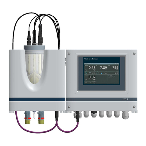
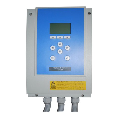
Evoqua WALLACE & TIERNAN SFC User manual

1
INSTRUCTION MANUAL
SFC
WALLACE & TIERNAN® MEASURING AND
CONTROL SYSTEM
Version V:3.08 and later

SFC
2
EN
In some countries, DEPOLOX, OSEC, Barrier, Chem-Ad and Wallace & Tiernan are trademarks of Evoqua, its subsidiaries or
affiliated companies. No part of this document may be reproduced in any form (printed, photocopy, microfilm, or any other
procedure) or saved, processed, copied, or distributed using electronic data systems - without the express prior written con-
sent of Evoqua Water Technologies GmbH.
All information in this document is considered reliable and corresponds to the generally applicable technical standards. Evo-
qua assumes no responsibility for the completeness of this information. Users are responsible for making sure that the pro-
duct is suitable for specific applications. Evoqua assumes no liability for specific or indirect damage or consequential
damage arising from the sale, resale or misuse of its products.
NOTICE
Translation of the original instruction.

SFC Contents
3
EN
Contents
1. Introduction ............................................................................... 6
1.1 Target groups ..........................................................................................................6
1.2 Conventions.............................................................................................................6
2. Safety......................................................................................... 7
2.1 Intended use............................................................................................................7
2.2 General safety instructions .....................................................................................7
2.3 Warranty conditions................................................................................................8
2.4 Specific Operating Phases .......................................................................................8
2.5 Notes on Special Dangers........................................................................................8
3. Description................................................................................. 9
3.1 Versions...................................................................................................................9
3.2 Technical Data .........................................................................................................9
3.2.1 Electronic module SFC.............................................................................................9
3.2.2 Flow block assembly DEPOLOX® 5.........................................................................12
3.2.3 VariaSens flow block assembly..............................................................................14
3.2.4 Flow block assembly DEPOLOX® Pool ...................................................................14
3.2.5 Y-style flow through assembly ..............................................................................14
3.2.6 Electrodes..............................................................................................................15
3.2.7 Membrane sensors................................................................................................16
3.2.8 CAN sensor modules SiDiSens...............................................................................16
3.3 Scope of supply .....................................................................................................18
3.3.1 Standard ................................................................................................................18
3.3.2 Options ..................................................................................................................18
3.4 Description ............................................................................................................18
3.4.1 Versions.................................................................................................................18
3.4.2 Design....................................................................................................................21
4. Functions ................................................................................. 25
4.1 General ..................................................................................................................25
4.2 Measurement inputs.............................................................................................27
4.2.1 3-electrode sensor DEPOLOX® 5 and DEPOLOX® Pool ..........................................27
4.2.2 pH measurement...................................................................................................30
4.2.3 Redox Measurement.............................................................................................31
4.2.4 Fluoride Measurement - Fluoride electrode W2T840142.....................................32
4.2.5 Fluoride Measurement - Fluoride electrode W3T169303.....................................33
4.2.6 Conductivity Measurement...................................................................................35
4.2.7 Sensor measuring module - membrane sensors...................................................36
4.2.8 mA/V input module...............................................................................................37
4.2.9 Temperature measurement ..................................................................................37
4.2.10 mA inputs of the A&C boards................................................................................37
4.2.11 CAN sensor measurement module SiDiSens .........................................................37

Contents SFC
4
EN
4.3 Outputs ................................................................................................................. 38
4.3.1 mA output............................................................................................................. 38
4.3.2 Relay outputs ........................................................................................................ 38
4.4 SFC CAN retrofit kit ............................................................................................... 39
4.5 Applications .......................................................................................................... 40
4.5.1 Application 1 - Process measurement .................................................................. 41
4.5.2 Application 2 ......................................................................................................... 43
4.5.3 Application 2 - Single feed forward with process measurement.......................... 44
4.5.4 Application 2 - Single feedback closed loop control with process measurement 46
4.5.5 Application 2 - Compound loop with process measurement ............................... 47
4.5.6 Application 3 - Single feed forward without process measurement .................... 52
4.6 Controller outputs ................................................................................................ 54
4.7 Control parameters............................................................................................... 56
4.8 Alarms ................................................................................................................... 60
4.9 Adaption ............................................................................................................... 63
4.10 Sample water inlet disinfection ............................................................................ 66
4.11 Serial interfaces .................................................................................................... 69
4.12 CAN interface........................................................................................................ 70
4.13 Fieldbus................................................................................................................. 72
4.14 Firmware update .................................................................................................. 72
4.15 Actuator feedback................................................................................................. 74
4.16 Digital inputs ......................................................................................................... 74
4.17 SD memory card.................................................................................................... 74
4.18 Unit configuration................................................................................................. 76
4.19 Special Features .................................................................................................... 76
5. Installation............................................................................... 77
5.1 Transport and storage........................................................................................... 77
5.2 Installation ............................................................................................................ 77
5.3 Commissioning...................................................................................................... 87
5.3.1 Installation guide .................................................................................................. 87
5.3.2 Pour in the cell sand (only with DEPOLOX® 5 and DEPOLOX® Pool)..................... 89
5.3.3 Inserting and Connecting Sensors......................................................................... 90
5.3.4 Replace standard cell body cover (optional) ........................................................ 93
5.3.5 Connecting the sample water and starting up, taking DEPOLOX® 5
as an example ....................................................................................................... 93
5.3.6 Fitting the fine filter .............................................................................................. 99
5.3.7 Connect the device to the power supply ............................................................ 100
5.3.8 Attaching the labeling field................................................................................. 100
5.3.9 Mounting the housing covers ............................................................................. 101
5.3.10 Switching the device on ...................................................................................... 101
5.3.11 Setting the applications ...................................................................................... 101
5.3.12 Positioner calibration with compound-loop-control and single feed back
control................................................................................................................. 102
5.3.13 Positioner calibration with SFC (application 3) or single feed forward
(application 2) ..................................................................................................... 103
5.4 System shut down............................................................................................... 104

SFC Contents
5
EN
6. Operation............................................................................... 105
6.1 Display and operator controls .............................................................................105
6.2 Notes on operation .............................................................................................108
6.3 Menu structure ...................................................................................................109
6.4 Calibration ...........................................................................................................130
6.4.1 Temperature calibration .....................................................................................131
6.4.2 3-electrode cell (DEPOLOX® 5 and DEPOLOX® Pool) calibration.........................131
6.4.3 Membrane sensors calibration............................................................................132
6.4.4 pH calibration ......................................................................................................133
6.4.5 Redox calibration (mV)........................................................................................134
6.4.6 Conductivity calibration ......................................................................................135
6.4.7 Fluoride calibration .............................................................................................135
6.5 Errors and remedies ............................................................................................137
6.5.1 Error messages ....................................................................................................137
6.5.2 Error.....................................................................................................................140
7. Maintenance .......................................................................... 141
7.1 Maintenance Schedules ......................................................................................141
7.2 Checking for tightness (daily) ..............................................................................142
7.3 Checking the cell sand (weekly) ..........................................................................142
7.4 Maintenance of flow block assembly DEPOLOX® 5.............................................142
7.4.1 Changing sell sand with the 3-electrode cell DEPOLOX® 5, DEPOLOX® Pool ......142
7.4.2 Check electrolyte level of the 3-electrode cell DEPOLOX® 5...............................143
7.5 Maintaining membrane sensors..........................................................................145
7.6 Maintaining Redox electrode ..............................................................................145
7.7 Maintaining pH electrode....................................................................................146
7.8 Maintaining fluoride electrode ...........................................................................146
7.9 Maintaining conductivity electrode ....................................................................146
7.10 Changing the fuse on the A&C board..................................................................147
7.11 Replacing the battery ..........................................................................................147
8. Complete Units, Retrofit Kits and Spare Parts......................... 148
9. Wiring Diagrams..................................................................... 179
10. Declarations and certificates .................................................. 185
11. Settings Table......................................................................... 189

1. Introduction SFC
6
EN
1. Introduction
1.1 Target groups
This instruction manual provides the informa-
tion for installation, operating and mainte-
nance personnel. It is required for operation
and maintenance of the unit.
This instruction manual is intended for the
operating personnel. It contains important
information for safe, reliable, trouble-free and
economical operation of the unit. Observance
of this information helps to prevent danger,
lowers repair costs, reduces down-times, and
also increases the reliability and service life of
the unit.
The chapters on installation and maintenance
are solely provided for trained service person-
nel. These sections contain important infor-
mation on the installation, configuration and
commissioning of the unit as well as informa-
tion on its repair.
All persons working with the unit must have
read and understood the operating instructi-
ons, in particular, the safety instructions it con-
tains.
1.2 Conventions
This instruction manual contains a number of
notes with different priorities that are labeled
with pictograms.
DANGER
Immediate danger to life and limb! If the
situation is not corrected, death or serious
injury will result.
WARNING
Danger to life and limb! If the situation is not
corrected, death or serious injury can result.
WARNING
Electrocution hazard.
CAUTION
If this note is not observed, moderate or
minor injury or damage to equipment can
result.
CAUTION
Environmental hazard!
Do not throw away or burn the
batteries!
Batteries must be disposed of at a
collection point.
NOTICE
These notes indicate a material risk or pro-
vide useful information to make working
with the SFC easier.

SFC 2. Safety
7
EN
2. Safety
2.1 Intended use
The SFC is exclusively designed for measure-
ment and control tasks required for the treat-
ment of waste water, potable water,
industrial water, and bathing water.
The operational safety of the unit is only gua-
ranteed if it is used in accordance with its
intended application. The unit may only be
used for the purpose defined in the order and
under the operating conditions indicated in
the technical specifications.
Compliance with the intended use also inclu-
des reading this operating manual and obser-
ving all the instructions it contains.
Furthermore, all inspection and maintenance
work must be performed at the prescribed
intervals.
The operator bears full and sole responsibility
if this unit is put to any use which does not
comply strictly and exclusively with this inten-
ded use.
2.2 General safety instructions
Evoqua Water Technologies GmbH attaches
great importance to ensuring that work on its
system is always perfectly safe. This was
already taken into account in the design of the
system, by the integration of safety features.
Safety instructions
The safety instructions in this documentation
must always be observed. These do not affect
the validity of any additional national or com-
pany safety instructions.
Safety instructions on the system
All safety instructions attached to the system
itself must be observed. They must always be
complete and easily legible.
Technical standard
The system or unit has been constructed in
accordance with state-of-the-art technology
and the accepted safety regulations. However,
in the event of the system or unit being used
by persons who have not been adequately
instructed, risks to life and limb of such per-
sons or third parties and damage to the system
or unit itself or to other property cannot be
ruled out. Work not described in this operating
manual may only be performed by authorized
personnel.
Personnel
The operator of the system must ensure that
only authorized and qualified specialized per-
sonnel are permitted to work with and on the
unit within their defined scope of authority.
„Authorized specialists“ are trained technici-
ans employed by the operator, by Evoqua, or,
if applicable, the service partner. Only quali-
fied electricians may perform work on electri-
cal components.
Spare parts / components
Trouble-free operation of the system is only
guaranteed if original spare parts and compo-
nents are used in precisely the combination
described in this operating manual. Failure to
observe this instruction may incur the risk of
malfunction or damage to the system.
Modifications and extensions
Never attempt to perform any modifications,
extensions or conversions to the unit without
the written approval of the manufacturer!
These could have an adverse affect on safety!
Electrical power
During normal operation, the control unit
must remain closed.
Before starting any assembly, inspection,
maintenance, or repair work, the system must
be switched OFF using the emergency stop
switch and the switch must be secured against
reactivation.
Connect all cables in accordance with the
wiring diagram.
Waste disposal
Ensure safe and environmentally-friendly dis-
posal of agents and replaced parts.

2. Safety SFC
8
EN
2.3 Warranty conditions
The following must be observed for compli-
ance with warranty conditions. If any of the
conditions are not met, the warranty is void.
• Installation, commissioning by Evoqua
technicians or trained and authorized spe-
cialized personnel, e.g. of contracted com-
panies
• Intended use
• Observation of the operational parame-
ters and settings.
• The unit may only be operated by trained
personnel.
• An operating log book must be kept (only
in the public sector).
• Only approved calibration chemicals may
be used
• The unit must not be exposed to frost.
• Maintenance work must be executed
• Use of original spare parts
2.4 Specific Operating Phases
Normal operation
• Never employ any working methods
which could affect safety!
• Only run the unit when the housing is clo-
sed!
• Inspect the unit at least once daily for
externally visible damage and faults!
Inform the responsible person/authority
immediately of any detected changes
(including any changes in the operating
performance)!
• In the event of malfunctions, always
switch the unit off immediately! Have
malfunctions remedied immediately!
Installation and maintenance work
• Always perform installation or mainte-
nance work in accordance with this ope-
rating manual or the technical
documentation for installed unit compo-
nents!
• Secure the unit against activation during
installation and maintenance work!
• Always retighten released screw connec-
tions!
• Never use corrosive cleaning agents!
Use only a damp cloth to clean the unit.
• Ensure safe disposal of agents and repla-
ced parts in accordance with environmen-
tal regulations!
2.5 Notes on Special Dangers
• Only use original fuses with the prescri-
bed current rating! In the event of a fault
in the electrical power supply, switch the
unit off immediately!
• Only qualified electricians or trained per-
sonnel supervised by a qualified electri-
cian are permitted to perform any work
on electrical components in accordance
with valid electro-technical regulations.
• If stipulated, disconnect all parts of the
unit from the power supply before perfor-
ming any inspection, maintenance or
repair work. Then first test the disconnec-
ted components to ensure they do not
carry any voltage.
• Inspect/check the electrical system of the
unit regularly. Remedy any faults imme-
diately!
• Connect disconnected cables in accor-
dance with the wiring diagram!
• When handling agents and chemical sub-
stances always observe the safety regula-
tions valid for each product!
• Always remove leaked agents immedia-
tely with a suitable binder or wipe up with
a cloth. Danger of slipping!
• Always collect and dispose of agents or
used cleaning material separately and in
accordance with valid national regulati-
ons!

SFC 3. Description
9
EN
3. Description
3.1 Versions
There are two versions of the SFC. They differ
in the type and number of inputs and outputs
that are available and in terms of functionality.
Both versions are available either as control
cabinet units or wall units.
Version 1 (SFC with sensor measuring
module)
This version supports all applications 1 – 3
(see 4.5 “Applications”)
• slot for 1 sensor module
•4relays
• 2x mA input
• 1x feedback input
• 2x digital input
• 1x temperature input PT 1000
•1xmAoutput
• 1x SD memory card receptacle
•1xCANinterface
• 1x RS485 interface
• 1x RS232 interface for Gateway
• 1x interface for firmware updates
Version 2 = SFC SC
This version only supports application 3 (see
4.5 “Applications”) without the possibility of
recording measurements using the sensor
measuring module.
•2relays
• 1 x mA input
• 1x feedback input
•2xdigitalinput
•1xmAoutput
• 1x interface for firmware updates
3.2 Technical Data
3.2.1 Electronic module SFC
Housing Dimensions (WxHxD) 185 x 265 x 145 mm
Weight approx. 2.5 kg
Protection type IP 66
Mains connection 100 – 240 V AC ± 10%, 50 – 60 Hz, 15 W, Fuse 1A time lag 250 V
Type: 5 x 20 mm
24 V DC ± 20%, 15 W, Fuse 1 A time lag 250 V
Type: 5 x 20 mm
Insulation Overvoltage category 2
Pollution degree 2
Measuring category I
CAUTION
Do not use the device in measuring categories II, III and IV.

3. Description SFC
10
EN
Operating conditions Ambient temperature 0 – 50 °C
Humidity < 80 %
Environment Indoor use. No direct sunlight
max. altitude 2000 m
Atmospheric pressure 75 – 106 kPa
Storage temperature -20 – +70 °C
Noise emission <45 dB
Digital inputs 2x inputs for voltage-free contact (< 100 Ohm) power supply via SFC
(12 V)
DI 1: Sample water monitoring / freely selectable in menu
DI 2: Freely selectable in menu
Measurement inputs 1x temperature input PT 1000 (0°C – 50°C) with sensor error display
(not with Version 2)
1x feedback input
positioner position feedback
Potentiometer 1kOhm or 5kOhm, 0 – 1 V, 0 – 20 mA (selectable via
DIP switch)
1x measured value input (electrically isolated up to 50 V to ground) for
plug-in cards of the sensor measuring module (not with Version 2):
• 3-electrode cell for chlorine, chlorine dioxide or potassium per-
manganate
• Membrane sensors for total chlorine TC1/TC3, free chlorine FC1/
FC2, chlorine dioxide CD7/CD10.1, ozone OZ7/OZ10.1
•pHvalue
•Redoxvoltage
• Fluoride
• Conductivity
• mA/V input
1x mA input for flow rate 0 – 20 mA/4 – 20 mA
In SFC units with a 24 V supply voltage this input is not electrically iso-
lated from the 24 V DC supply voltage.
1x mA input for external setpoint or dosing factor
0 – 20 mA/4 – 20 mA (not with Version 2)
In SFC units with a 24 V supply voltage this input is not electrically iso-
lated from the 24 V DC supply voltage.
Interfaces 1x RS232 for firmware updates (not galvanically isolated)
1x RS485 (optional) (not with Version 2) for connection to:
•ProcessMonitoringSystem
• OPC Server Data Access V2.0
•SECO-S7
The RS485 interface is electrically isolated up to 50 V to ground.
1 x CAN interface to connect to CAN sensors
1x RS232 interface for Gateway module (not with Version 2)
Display and operating
unit
1 x Operating panel with 9 keys
1 x Graphic display:
• Resolution 128 x 64 pixels
• white background illumination

SFC 3. Description
11
EN
Relay outputs 4 relay outputs (with Version 1) or
2 relay outputs (with Version 2) (each with two-way switch)
Switching values 5 A, 250 V AC, 1250 VA max
5 A, 220 V DC, 150 W max
UL/CSA-rating 5 A, 1/6 HP 125, 250 V AC
5 A, 30 V DC, 30 W max
1 A, 30 V DC - 0.24 A, 125 V DC
mA output 1x mA output (freely configurable):
• Output 0/4 – 20 mA
•Accuracy<0.5%FS
• Load max. 500 Ohm
• Temperature drift max. 0.2% / 10°C
• Load monitoring
• Electrically isolated up to 50 V to earth
Memory card 1x SD memory card slot for installing an SD memory card (not with Ver-
sion 2)
DES measuring
module 3-electrode
cell
Sensor 3-electrode cell
Principle of operation Potentiostatic amperometry
Temperature drift max. 0.2% / 10k
Linearity error < 0,1 %
Calibration Pre-calibrated
Upot cell voltage 0 – +1000 mV
Upot accuracy ± 20 mV
Upot temperature drift 0.5% / 10K
Input signal -7 – 1000 µA
Temperature input PT 1000 (optional)
Measuring ranges 10, 70, 100, 200, 1000 µA (depending on
the type of the DES module)
DES module
membrane sensors
Sensor Membrane covered 3-electrode sensor
Principle of operation Potentiostatic amperometry
Temperature drift max. 0.2% / 10k
Linearity error < 0,1 %
Calibration Pre-calibrated
Input signal -7 – 1000 µA
Measuring ranges 70, 100, 200, 1000 µA
pH measuring
module for pH value
Sensor input pH single rod electrode
Temperature drift max. 0.2% / 10k
Linearity error < 0,1 %
Calibration Pre-calibrated
Input signal -1000 – +1000 mV
Input impedance 1013 Ohm

3. Description SFC
12
EN
3.2.2 Flow block assembly DEPOLOX® 5
mV measuring
module for Redox
Sensor input Redox single rod electrode
Temperature drift max. 0.2% / 10k
Linearity error < 0,1 %
Calibration Pre-calibrated
Input signal -1000 – +1000 mV
Input impedance 1013 Ohm
mS measuring
module for
conductivity
Sensor input LF325
Temperature measuring
range
0 – +50 °C
Temperature drift < 0,2 %
Calibration Pre-calibrated
Linearity error < 0,5 %
Measuring range 0,1 – 200 mS/cm
mA/V measuring
module for analog
input
Sensor input mA signal or V signal
Temperature drift max. 0.2% / 10k
Linearity error < 0,1 %
Calibration Pre-calibrated
Measuring ranges 0/4 – 20 mA (scalable) or
0 – 10 V (scalable)
F- measuring module
for fluoride
Sensor input Fluoride single rod electrode
Calibration Pre-calibrated
Measuring range 0.2 – 20.0 mg/l
Temperature drift max. 0.2% / 10k
Linearity error < 0,1 %
Housing Dimensions (WxHxD) 215 x 375 x 155 mm
Weight approx. 1.5 kg
Multi sensor Switching point 21 l/h +/- 3 l/h
Switching hysteresis 2 l/h
Temperature sensor PT 1000
Measured variables Free chlorine, chlorine dioxide, ozone,
potassium permanganate
Measuring ranges 70, 100, 200, 1000 µA
Typical output signal approx. 20 µA/mg/l free chlorine
Measuring system Potentiostatic 3-electrode system
Reference electrode Silver/Silver chloride/Potassium chloride
solution
Working electrode Platinum
Other materials PVC, PMMA, ABS, ECTFE, PTFE, stainless
steel, EPDM, FKM, NBR

SFC 3. Description
13
EN
The HOCI curve describes the influence of the pH value on the DEPOLOX® 5.
Fig. 1 HOCI curve
Multi sensor Cable length 650 mm
Electrolyte Potassium chloride solution, 3 mol
Zero point calibration by stopping flow rate or dechlorinated
sample water typ. zero current approx. 1
µA
Response time T90: < 20 sec.
Temperature compensation
0 – 50 °C
Storage temperature -10°C – +50°C (without electrolyte)
Influence of the pH value HOCl curve, operating range pH 5.0 –
pH 8.5
Cross-sensitivity other oxidation agent: copper-based
algaecide
Water quality swimming pool, potable, industrial and
process water
Sample water temperature
max. +50 °C
Conductivity min. 200 µS/cm
Service life Life of the electrolytes in operation
approx. 6 months
Service life of electrodes in operation
approx. 5 years (shortened by poor water
quality, e.g. sand, dirt)
Volumetric flow
control
Flow rate approx. 33 l/h (controlled)
Control range 0.2 – 4.0 bar
Back pressure • non-pressurized version (free drain)
• pressurized version 1.5 bar
Connections Sample water PVC hose 6x3 mm or PE hose 6x1 mm
Thread connection G1/2“ or NPT 1/4“

3. Description SFC
14
EN
3.2.3 VariaSens flow block assembly
3.2.4 Flow block assembly DEPOLOX® Pool
3.2.5 Y-style flow through assembly
Housing Dimensions (WxHxD) 215 x 375 x 155 mm
Weight approx. 1.5 kg
Connections Sample water PVC hose 6 x 3 mm or PE hose 6 x 1 mm
Thread connection G1/2“ or NPT 1/4“
Flow control valve Flow rate approx. 33 l/h (controlled)
Control range 0.2 – 4.0 bar
Back pressure • non-pressurized version (free drain)
• pressurized version 1.5 bar
Sample water Water quality swimming pool, potable, industrial and
process water
Sample water temperature
max. +50 °C
Multi sensor Switching point 21 l/h +/- 3 l/h
Switching hysteresis 2 l/h
Temperature sensor PT 1000
Housing Dimensions (WxHxD) 215 x 375 x 155 mm
Weight approx. 1.5 kg
Connections Sample water PVC hose 6 x 3 mm or PE hose 6 x 1 mm
Thread connection 1/2"
Flow control valve Flow rate approx. 33 l/h (controlled)
Control range 0.2 – 4.0 bar
Back pressure • non-pressurized version
or
• pressurized version 1.5 bar
Sample water Water quality Swimming pool water
Sample water temperature
max. +50 °C
Multi sensor Switching point 21 l/h +/- 3 l/h
Switching hysteresis 2 l/h
Temperature sensor PT 1000
Y-style flow through
assembly pH/mV
Back pressure non-pressurized/pressurized Version
(max. 6 bar)
Sample water temperature
max. +50 °C
Y-style flow through
assembly fluoride
Back pressure Non-pressurized version
Sample water temperature
max. +50 °C
Y-style flow through
assembly conductivity
Back pressure pressurized version up to 6 bar
Sample water temperature
max. +50 °C

SFC 3. Description
15
EN
3.2.6 Electrodes
DES 3-electrode chlo-
rine measuring cell
(glass electrode) for
DEPOLOX® Pool flow
block assembly
Measuring system 3-electrode sensor with additional stock
of electrolyte salt
Principle of operation Potentiostatic amperometry
Temperature compensation
0–50°C
Temperature drift max. 0.2 % / 10 K
Measuring range 0,1 – max. 20 mg/l
Upot 0 – +1000 mV
Reference electrode Silver/Silver chloride/Potassium chloride
solution
Working electrode Platinum
Other materials Vitreous body
Storage temperature -10 – +30 °C
Water quality Swimming pool water
pH electrode Max. measuring range pH 0 – 12
Operating temperature
range
-5 – +80 °C
Storage temperature range
-5 – +30 °C
Sample water conductivity
200 µS/cm – 200 mS/cm
Max. operating pressure 6 bar
ORP electrode Max. measuring range -1000 – +1000 mV
Operating temperature
range
-10 – +80 °C
Storage temperature range
-5 – +30 °C
Sample water conductivity
200 µS/cm – 200 mS/cm
Max. operating pressure 6 bar
Fluoride electrode Max. measuring range 0.2 – 20 mg/l
Operating temperature
range
0 – +80 °C
Storage temperature range
-5 – +30 °C
Sample water conductivity
200 µS/cm – 200 mS/cm
Max. operating pressure non-pressurized
pH range pH 5 to 8
Conductivity elec-
trode
Measuring system 4-electrode system LF325
Principle of operation 4 conductor measurement
Operating temperature
range
-5 – +100 °C
Storage temperature range
-5 – +50 °C
Cell constant 0.48 cm-1 ±1.5 %

3. Description SFC
16
EN
3.2.7 Membrane sensors
3.2.8 CAN sensor modules SiDiSens
NOTICE
Technical data
Please refer to the separate instruction manual of the membrane sensors "Free Chlorine FC2",
"Total Chlorine TC3", "Chlorine Dioxide CD10.1" and "Ozone OZ10.1".
Maximum allowable
operating pressure
0.5 bar (7.25 PSI) only with a suitable flow cell!
No pressure impulses and/or vibrations.
Please note the back pressure of the flow cell!
Housing Dimensions (WxHxD) 40 x 120 x 35 mm (without cable)
Weight about 200 – 250 g depending on the ver-
sion
Protection rating IP66
Power supply 24 V DC ± 20%; max. 2 W
Operating conditions Ambient temperature 0 - 50 °C
Humidity < 80 %
Environment No direct sunlight
Atmospheric pressure 75 - 106 kPa
Max. altitude 2,000 m
Storage temperature -20 - 50 °C
Noise emission <45 dB
Interface CAN bus interface (electrically isolated up to 50V to earth)
Measurement inputs SiDiSens pH
Sensor type Single-rod electrode for pH
Input signal -400…+400 mV
Temperature drift <0.1 %/10K
Linearity error < 0,1 %
Input impedance 1013 Ohm
Calibration Pre-calibrated

SFC 3. Description
17
EN
Connections Power supply +
CAN bus
Connecting cable with 5-pin M12 plug
and 5-pin M12 socket for CAN bus
terminal plug or to connect other CAN
bus components:
Pin 1 screen
Pin 2 +24V
Pin 3 0V
Pin 4 CAN high
Pin 5 CAN low
Measurement input Plug connector compatible with sensor
M12 plug M12 socket

3. Description SFC
18
EN
3.3 Scope of supply
3.3.1 Standard
Electronic module SFC incl. accessories set
and mounting set, comprising:
•4xscrewsØ5mm
•4xdowelsØ8mm
•4xwashers
• 3 multiple seal inserts 2x6 mm
• 3 multiple seal inserts 4x5 mm
• 3 reducing sealing rings Ø 8 mm
• 4 bolts for multiple seal inserts 5 mm
• 2 bolts for multiple seal inserts 6 mm
3.3.2 Options
Flow block assembly
•DEPOLOX®5 (non-pressurized or
pressurized version)
•DEPOLOX®Pool (non-pressurized or
pressurized version)
• VariaSens (non-pressurized or pressurized
version)
• Y-style flow through assemblys (non-pres-
surized or pressurized version)
Sensor measuring module retrofit kit inclu-
ding accessories:
•pH
•Redox
• Conductivity
•Fluoride
•Freechlorine(FC2)
• Chlorine dioxide selective (CD10.1 )
• Ozone selective (OZ10.1)
• Total chlorine (TC3)
• 3-electrode cell DEPOLOX®5
• 3-electrode cell DEPOLOX®Pool
• 3-electrode cell DEPOLOX®4 with PT 100
•mA/Vinputcard
• CAN sensor measurement module SiDiSens pH
• CAN sensor measurement module SiDiSens DES
3.4 Description
3.4.1 Versions
The SFC is available in two different versions
(see 3.1 “Versions”), each in two voltage varia-
tions:
• 100 – 240 V AC
• 24 V DC
Depending on the application, the SFC can be
operated either without a flow block assembly
(no sensor measuring module) or in connec-
tion with a flow block assembly and sensor
measuring module.
The flow block asssembly is available in diffe-
rent versions:
•DEPOLOX®5 - non-pressurised version
(Sample water drains freely)
•DEPOLOX®5 - pressurised version
(Sample water is recycled through the sys-
tem cycle)
•DEPOLOX®Pool - Non-pressurized version
•DEPOLOX®Pool - Pressurized version
• VariaSens - non-pressurized version, see
“Overview” on Page 35
• VariaSens - pressurized version, see
“Overview” on Page 35
• Various Y-style flow through assemblys
NOTICE
You will find the order numbers under 8.
“Complete Units, Retrofit Kits and Spare
Parts”.
NOTICE
• All retrofit kits or sensor measurement
modules, except for the SiDiSens measu-
rement modules, are available with or
without the process control option.
•
The pressurized version
DEPOLOX®5 and
DEPOLOX®Pool
can be retrofitted with a
membrane sensor. Please note that the
standard cell body cover must be
replaced by an optional cell body cover
(W3T417351 - DEPOLOX®5 or
W3T417269 - DEPOLOX®Pool).
NOTICE
The selection is customised according to the
type of measured values to be recorded.

SFC 3. Description
19
EN
Overview
Non-
pressurized
version
DEPOLOX® 5
Pressurized
version
DEPOLOX® 5
Pressurized
version
DEPOLOX® 5
with cell body
cover
W3T417351
(optional)
Non-
pressurized
version
VariaSens
Pressurized
version
VariaSens
Non-
pressurized
version
DEPOLOX®
Pool
Pressurized
version
DEPOLOX®
Pool
Pressurized
version
DEPOLOX®
Pool with cell
body cover
W3T417269
(optional)
Y-style flow
through
assembly
1) W3T171332
2) W3T159950
3) W3T158503
4) W3T163663
A Membrane sensor for free chlorine FC1/FC2, total chlorine TC1/TC3, chlorine dioxide CD7/CD10.1,
ozone OZ7/OZ10.1
BRedox
C Fluoride or conductivity
DpH
E 3-electrode sensor (single rod glass electrode)
FPlug
Example:
A
D C B
D C B
A
F
BC
D
A
C B D
C
D B A
A
D E C B
D C B
E
A
F
BC
D
E

3. Description SFC
20
EN
Non-pressurized version
DEPOLOX® 5
Pressurized version
DEPOLOX® 5
Non-pressurized version
VariaSens
Pressurized version
VariaSens
Non-pressurized version
DEPOLOX® Pool
Pressurized version
DEPOLOX® Pool
Y flow-through
adapter
Free chlorine, ClO2,
KMnO4, O3
3-electrode
measuring cell
XX-- XX--
Membrane sensor FC1/
FC2, TC1/TC3, CD7/
CD10.1 or OZ7/OZ10.1
Membrane-
covered electrode
1x -- 2x
1x (only
OZ10.1
or
CD10.1)
1x -- --
pH pH0–12 XXXXXXX1/2)
Redox value -1000 –
+1,000mV
XXXXXXX1/2)
Fluoride 0,20 – 20,00 X -- X -- X -- X 4)
Conductivity 0,1–200mS/cmXXXXXXX 3)
„Multi sensor“ Temperature
(PT 1000) 0 – 50
°C
XXXXXX--
Flow rate moni-
tor (reed switch)
XXXXXX--
Earthing XXXXXX--
Ball valve
Sample water (inlet)
G1/2“connectionXXXXXX--
Ball valve
Sample water (outlet)
G 1/2“ connection -- X -- X -- X --
Preliminary filter Recommended
when using mem-
brane-covered
electrodes
X--XXX----
Checkvalve Glassball XXXXXX--
Volumetricflowcontrolfreedrain XXXXXX--
Factory setting: 33 l/h
Admission pressure:
0.2 – 4.0 bar
Max. back pres-
sure: 1.5 bar
XXXXXX--
Drain/extractspecimen XXXXXXX 4)
Calibration instrument
bracket
CalibrationaidXXXXXX--
NOTICE
Following membrane sensors were replaced:
• "Free Chlorine FC1"=> "Free Chlorine FC2"
• "Total Chlorine TC1" => "Total Chlorine TC3"
• "Chlorine Dioxide CD7" => "Chlorine Dioxide CD10.1"
• "Chlorine Ozone OZ7" => "Chlorine Ozone OZ10.1"
The membrane sensors FC1, TC1, CD7 and OZ7 are fully compatible with the SFC.
Other manuals for WALLACE & TIERNAN SFC
1
Table of contents
Other Evoqua Control System manuals
Popular Control System manuals by other brands

RF SOLUTIONS
RF SOLUTIONS Hornet-S2 manual

Ariston
Ariston 3319121 Assembly and operation instructions

Clarke
Clarke CPB1 User instructions

Comunello
Comunello BORDER 400 Installation and user manual

Pentair Pool Products
Pentair Pool Products Compool Installation and user guide

Balboa
Balboa VS510S instructions