8WT.050.810.010.DE.IM.0718
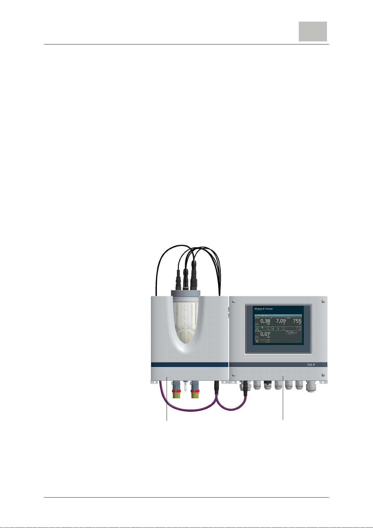
Safety 700 P electronics module
2.
Safety warnings on the unit All safety instructions attached to the unit itself must be observed.
These instructions must always be clearly legible and complete.
State-of-the-art technology The unit has been constructed in accordance with state-of-the-art
technology and the accepted safety regulations. However, if the
unit is used by persons who have not been adequately instructed,
risks to life and limb of such persons or third parties and damage
to the unit itself or to other property cannot be ruled out. Work not
described in this instruction manual must be performed only by
authorized personnel.
Personnel The operator of the overall system must ensure that only autho-
rized and qualified specialized personnel are permitted to work
with and on the unit within their defined scope of authority. "Autho-
rized, specialized personnel" refers to trained technicians
employed by the operator, the manufacturer, or, if applicable, the
service partner. Only qualified electricians must perform work on
electrical components.
Spare parts / components Trouble-free operation of the unit is only guaranteed if original
sparepartsand components areusedinprecisely the combination
described in this instruction manual. Failure to observe this
instruction may incur the risk of malfunction or damage to the unit.
Extensions and conversions Never attempt to perform any modifications, extensions or conver-
sions on the unit that could have an adverse affect on safety with-
out the written approval of the manufacturer.
Electrical power Only qualified electricians or trained personnel supervised by a
qualified electrician are permitted to perform any work on electrical
components in accordance with valid electro-technical regulations.
During normal operation, the controller must remain closed. Con-
nect the power cables in accordance with the wiring diagram.
Danger!
Risk of injury or death!
External voltages may be connected even with the operating volt-
age switched off. In the event of a fault in the electrical power sup-
ply, switch the device off immediately!
IT security The manufacturer offers ITsecurity mechanisms for its productsto
support secure system operation. We recommend checking on a
regular basis to see what information is available regarding IT
security developments for your products. Information on this can
be found on the Internet.