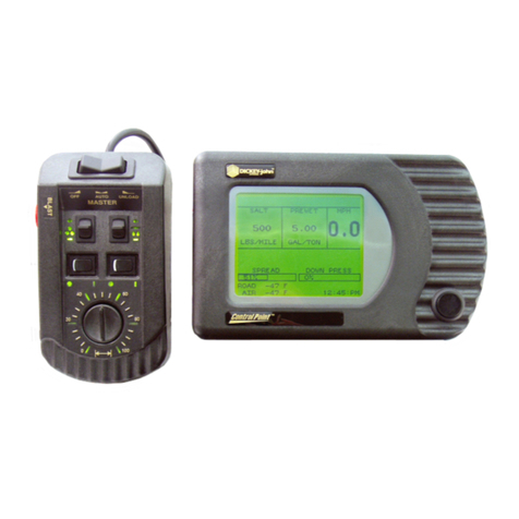
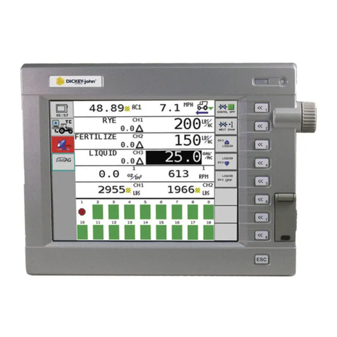
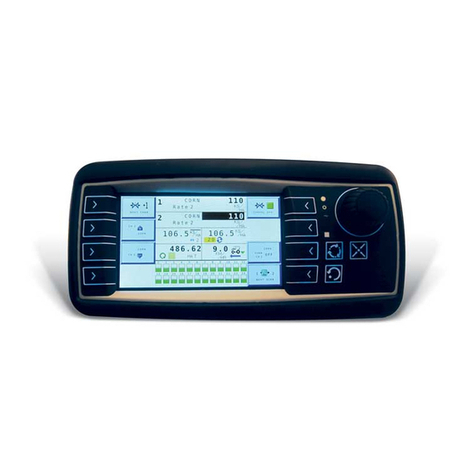
Dickey-John Flex4 Pro User manual

FLEX4 PRO™
PUBLIC WORKS CONTROL SYSTEM
Operator’s Manual
SINCE 1966
®
FLEX
PRO

OPERATOR’S MANUAL
Safety Notices........................................................................................................1
Disclaimer............................................................................................................................1
Introduction........................................................................................................... 3
Features ..............................................................................................................................3
Component Overview........................................................................................... 5
Flex4 Pro tablet..................................................................................................................5
Switch module functions......................................................................................................8
Rate control module............................................................................................................9
Output module...................................................................................................................11
Miscellaneous components...............................................................................................15
Installation............................................................................................................17
Operator switch module mounting bracket........................................................................17
Ram mount bracket installation.........................................................................................18
Operate screen overview....................................................................................27
Display settings (Camera/Display/Alarms)........................................................................29
Operation..............................................................................................................31
Pre-operating checklist......................................................................................................32
Spreading material............................................................................................................32
Blast...................................................................................................................................33
Pause ................................................................................................................................34
Material selection ..............................................................................................................35
Unload material .................................................................................................................36
Manual ground speed override..........................................................................................38
Automatic manual control channel override......................................................................39
Driver login ........................................................................................................................40
Route selection..................................................................................................................40
Boom section control.........................................................................................................41
Anti-ice feature ..................................................................................................................42
Accessory sensors ............................................................................................................42
Hydraulic accessory tool operation ...................................................................................44
Current and season run totals...........................................................................................44
Flex4 Pro programming ......................................................................................47
Passcode restrictions........................................................................................................47
Keyboard functions............................................................................................................48
Flex4 ProTM Control System / 1
6010541 Rev A

OPERATOR’S MANUAL
System programming.........................................................................................53
Operate mode (F1)............................................................................................................53
Anti-ice button mode feature.............................................................................................53
Granular Channel Setup (F2)............................................................................................55
Granular rate setup ...........................................................................................................56
Granular configuration (f2)................................................................................................59
Liquid channel setup (f3)...................................................................................................62
Liquid rate setup................................................................................................................63
Boom configuration (liquid/Anti-Ice)..................................................................................66
Auxiliary control channel configuration (f5).......................................................................71
Accessory sensors (F9) ....................................................................................................72
System setup (F10)...........................................................................................................84
Blast setup ........................................................................................................................84
Date and time....................................................................................................................85
Units and language...........................................................................................................86
Service ..............................................................................................................................87
Troubleshooting ................................................................................................................89
Output module setup (f11) ................................................................................................91
Data logging (F12) ............................................................................................................93
Driver setup.......................................................................................................................95
Calibrations .......................................................................................................103
Material and spinner system response calibrations (f6) .................................................103
Recording calibration data ..............................................................................................104
Maintaining calibration accuracy.....................................................................................105
Granular drop test calibration..........................................................................................106
Liquid drop test calibration (F6) ......................................................................................109
Auxiliary system response and drop test........................................................................112
Spinner system response calibration..............................................................................112
Import/export data files ....................................................................................121
Passcode enabled...........................................................................................................121
Export configuration files.................................................................................................121
Export log data files.........................................................................................................122
Import configuration files.................................................................................................125
Capture screen shot .........................................................................................127
Diagnostics........................................................................................................129
Perform a Diagnostics check (f7)....................................................................................129
Display PCECU...............................................................................................................131
Control module................................................................................................................131
Output module.................................................................................................................135
Troubleshooting................................................................................................137
Appendix A ........................................................................................................143
Appendix B Converting Constants..................................................................145
Fine Tuning Application...................................................................................................145
Calculating Spreader Constants .....................................................................................146
Appendix C.........................................................................................................147
2 / Flex4 ProTM Control System
6010541 Rev A

OPERATOR’S MANUAL
SAFETY NOTICES
Safety notices are one of the primary ways to call attention to potential
hazards. An absence of specific alerts does not mean that there areno
safety risks involved.
This Safety Alert Symbol identifies important safety
messages in this manual. When you see this symbol,
carefully read the message that follows. Be alert to
the possibility of personal injury or death.
Use of the word WARNING indicates a potentially hazardous
situation which, if not avoided, could result in death or serious
injury.
Use of the word CAUTION with the Safety Alert Symbol indicates a
potentially hazardous situation which, if not avoided, may result in
minor or moderate injury.
Use of the word CAUTION without the safety alert symbol
indicates a potentially hazardous situation which, if not avoided,
may result in equipment damage.
DISCLAIMER
DICKEY-john reserves the right to make engineering refinements or
procedural changes that may not be reflected in this manual. Material
included in this manual is for informational purposes and is subject to
change without notice.
Flex4 ProTM Control System
6010541 Rev A
SAFETY NOTICES / 1

OPERATOR’S MANUAL
Flex4 ProTM Control System
6010541 Rev A
SAFETY NOTICES / 2

OPERATOR’S MANUAL
INTRODUCTION
The DICKEY-john Flex4 ProTM Control System can simultaneously control
both granular and liquid snow and ice removal materials. Separate
channels for granular and liquid precisely controls and maintains the
desired applications.
The flow of material varies automatically in proportion to the changes in
ground speed so the application rate remains uniform. When Automatic
mode is enabled, spreading automatically starts when the truck begins to
move and automatically stops when the truck stops.
The operator interface consists of a:
•
Flex4 ProTMTablet
•
Operator Switch Module
Desired material application rates are entered on the Setup screens by
attaching a keyboard.
Figure 1e
Flex4 ProTM Tablet and Remote Operator Switch Module
FEATURES
•
Color touch screen display withstylus
•
4 channel closed-loop control of granular, liquid, auxiliary (liquidor
granular), and spinnerfunctions
•
Year-round application for roadside spraying, berming, and operation
of hydraulic tools
•
Day/night mode
•
Optional camera to view rear of truck to monitor material dispensing
and to avoid potentialaccidents
•
Compatible with vehicle and fleet data management systems
Flex4 ProTM Control System
6010541 Rev A
INTRODUCTION / 3

OPERATOR’S MANUAL
4 / INTRODUCTION
Flex4 ProTM Control System
6010541 Rev A

OPERATOR’S MANUAL
NOTE: Contact DICKEY-john Technical
Support to order optional
components at
1-800-637-3302.
COMPONENT OVERVIEW
Components included with the Flex4 ProTM Control System:
•
Flex4 ProTMtablet
•
Flex4 ProTM tablet mounting plate, bracket, andhardware
•
Rate control module
•
Operator Switch Module
•
Operator Switch Module mounting bracket andhardware
•
Cab power harness
•
Rate control moduleharness
•
PCECU (power controllerECU)
•
USB port hub
•
USB-CAN adapter
•
DC-DC converter
Optionalcomponents:
•
10’ CAN extensionharness
•
Output module andharness
•
Solenoid driver
•
Electric motor/pumpdriver
•
Camera 4.3mmlens
•
Camera to USB adaptercable
•
12V power adapter cameracable
•
20’ camera extension
•
Feedback sensors
FLEX4 PROTM TABLET
The Flex4 ProTM tablet is a color touch screen display providing
simultaneous viewing of:
•
Rates
•
Spread width
•
Vehiclespeed
•
Spread direction
•
Road temperature
•
Joystick selection
•
Accessory inputmonitoring
•
Multiple vehiclecameras
Flex4 ProTM Control System
6010541 Rev A
COMPONENT OVERVIEW / 5

OPERATOR’S MANUAL
Figure 2
Flex4 ProTM Tablet
TABLET SPECIFICATIONS
Physical and Environmental Characteristics:
Dimensions with case: 10.43”W x 7.07”H x0.70”D
(265 mm W x 179.6 mm H x 17.9 mm D)
Operating Temperature: 32 degrees F to +120 degrees F
(0 degrees C to +49 degrees C)
Storage Temperature: -22 degrees F to +160 degreesF
(-30 degrees C to +71 degrees C)
Humidity: 5% - 95% non-condensing
The Flex4 ProTM tablet should not be turned on until product
temperature stabilization occurs when exposed to different
temperature extremes.
Cab temperatures should be above 32 degrees for proper
operation.
Humidity levels should be below 95% before powering on device.
6/COMPONENTOVERVIEW
Flex4 ProTM Control System
6010541 Rev A

OPERATOR’S MANUAL
TABLET CONNECTIONS
Two tablet connections on the Flex4 ProTM tablet are used.
1.
Tablet power cable
2.
USB port (connects to ToughHub)
Figure 3
Flex4 ProTM Tablet Connections
volume
adjustment
power
button
Stylus
Flex4 ProTM Control System
6010541 Rev A
COMPONENT OVERVIEW / 7
USBport
Power
cable

OPERATOR’S MANUAL
OPERATOR SWITCH MODULE
The Operator Switch Module consists of buttons that control material
applicationrate and spread width knob toadjust spinnerspeedandregulate
spreading of material. The module is backlit for visibility during night
operation and is mounted next to the display,driver seat arm rest, or on side
of the electronic joystick hydrauliccontroller.
Figure 4
Operator Switch Module
Spread
Width
Knob
SWITCH MODULE FUNCTIONS
AUTO ON/OFF
The Auto On/Off button regulates the amount of material applied in relation
to the ground speed and turns the application of product on or off.
PAUSE
Pause button stops applying material but continues to calculate the total
miles driven. Auto mode must be active for the Pause feature to operate.
BLAST
The Blast button applies material at a pre-programmed dispersal rate in
Auto mode and manual override with Auto Switch in ON or OFF position.
RATE (-)
The Rate (-) button decreases the amount of pre-programmed material with
each button press in Auto mode and manual override.
RATE (+)
The Rate (+) button increases the amount of pre-programmed material with
each button press in Auto mode and manual override.
SPREAD WIDTH KNOB
Spread Width Knob adjusts the spinner speed to regulate material spread
width. The spread width percentage displays on the console. Pressing the
spread width knob also selects a channel toadjust.
8/COMPONENTOVERVIEW
Flex4 ProTM Control System
6010541 Rev A

OPERATOR’S MANUAL
USB DATA PORT CONNECTION
USB data port for data download and keyboard connection is located below
the switch module. The USB port can be used for the following purposes:
–
Transmission of current operation information and logged data for
export to externalhardware.
–
Accepts a USB memory device forexporting logged spread data for
transfer to a laptopcomputer.
–
Import of system firmware updates to tablet and mastercontrol
module from USB memorydevice.
–
Imports system configuration files to program each tabletand
master control module with system calibrationvalues.
Figure 5
USB Data Port Connection
RATE CONTROL MODULE
The Rate Control Module houses the system’s primary interface device. All
system parameters, constants, and memory are stored in the module and
controls material application by interfacing with valves and feedback
sensors.
1.
Select an area on the vehicle chassis to mount the RateControl
Module that allows for easy hookup andaccess.
2.
Use the enclosure as a template to mark the location of themounting
holes.
3.
Drill four 9/32 inch diameter holes wheremarked.
Flex4 ProTM Control System
6010541 Rev A
COMPONENT OVERVIEW / 9
Spread
Width
Knob
USBPort

OPERATOR’S MANUAL
Figure 6
Rate Control Module
3.93”
IMPORTANT: Do not use the enclosure as a guide when drilling. Do
not overtighten nuts as this may damage the mounting
tabs of the enclosure.
The module can be mounted in any of the following orientations:
Figure 7
Acceptable Orientation
PREFERREDACCEPTABLEACCEPTABLE
Do not install the module in any orientation other than shown in
(Figure 7). The connection wires must not be mounted upward as
moisture can collect inside the unit and damage the circuits.
4.
Mount with the label side of module facing out. Do not mount withthe
connector facing up (seeCaution).
Connect any additional adapter harnesses to the module harness.
The Rate Control Module harness can accept an extension harnesses or
the output harness.
10/ COMPONENTOVERVIEW
Flex4 Pro
TM
Control System
6010541 Rev A
7.45”
7.0”
6.80”

OPERATOR’S MANUAL
The Rate Control Harness provides a connection to the following inputs:
–
1 granular controlchannel
–
1 liquid control channel (prewet oranti-ice)
–
1 auxiliary/spinner control channel (liquid orgranular)
–
1 auxiliary channel (liquid or granularchannel)
–
2 application ratesensors
–
4 hydraulic valves(PWM)
–
1 down pressuresensor
–
1 control valve (Servo)
–
2 flow meters
–
1 gate height sensor
–
1 ground speedsensor
–
1 remoteon/off
–
2 digitalsensors
–
1 hopper levelsensor
–
1 tank levelsensor
–
2 6-pin Servoconnectors
–
1 road/air temperature sensor adapter(optional)
5.
Install sensors,valves, etc. per the instructions included with the items.
6.
Install PWM valve assembly and feedback sensor for each control loop
and connect the devices to their respective inputs on the harness
making certain to match PWM 1/Servo 1 with FB1, PWM2/Servo 2 with
FB2, etc.
7.
Secure any unused and excesscable lengths where necessary.
OUTPUT MODULE
The Output Module is an auxiliary to the Rate Control Module to drive
additional accessories installed on the vehicle such as boom section shutoff
valves, open and close V-Box gates, switching valves for front/rear
conveyors, switching valves for left/right discharge cross conveyors, and
accessory 12 volt switched output.
1.
Select an area on the vehicle chassis to mount the module thatallows
for easy hookup and access. Extensions may be used to reach
members installed on remote areas of thevehicle.
2.
The module can be mounted in the same orientations as the rate
control module as illustrated in (Figure7).
Flex4 ProTM Control System
6010541 Rev A
COMPONENT OVERVIEW / 11

0.630
2.36
4.00
4.63
5.24
OPERATOR’S MANUAL
Figure 8
Output Module
.291
2 HOLES
4.68 1.37
Do not install the module in any orientation other than illustrated
in (Figure 7). The connection wires must not be mounted upward
as moisture can collect inside the unit and damage the circuits.
Ensure that module connectors do not face upward.
3.
Mount with the label side of the module facingout.
4.
Tobolt the member to a frame:
–
Use the enclosure as a template to mark the location ofthe
mounting holes.
–
Drill two 9/32 inch diameter holes wheremarked.
–
Attach to frame using 1/4 x 20 bolts or other fastening devicesas
illustrated in Figure 8.
Do not use the enclosure as a guide when drilling. Do not
overtighten nuts as this may damage the mounting tabs on the
enclosure.
12/ COMPONENTOVERVIEW
Flex4 ProTM Control System
6010541 Rev A

TRUCK
FRAME
OR
BED SUPPORT
1/4
TH
BO
L
OT
FA
S
DE
OPERATOR’S MANUAL
Figure 9
Securing Member with Bolts
TRUCK
FRAME
OR BED
SUPPORT
1/4 x 20 BOLT
1/4 FLAT WASHER
1/4 NUT
1/4 SPLIT
LOCKWASHER
1/4 FLAT WASHER
1/4 NUT
x 20
READED "U"
T OR
HER
TENING
VICE
1/4 SPLIT LOCKWASHER
5.
Totie strap the module to a frame:
–
Use one long tie strap to loop around the member bodyand
through both mounting holes as illustrated in Figure9.
–
If necessary, drill mounting holes following the procedure described
above.
–
Securely tighten tiestrap.
–
Install a second tie strap toward the label end of the enclosurefor
additional support.
Flex4 ProTM Control System
6010541 Rev A
COMPONENT OVERVIEW / 13

7.45”
7.0”
6.80”
OPERATOR’S MANUAL
Figure 10
Securing Member with Tie Straps
TRUCK
FRAME
OR
BED
SUPPORT
6.
Connect an output module harness to the output module andconnect
the output module harness to the Power/CAN backbone, refer to
(Figure 16).
7.
Connect each module harness to its module inserting both connectors
until the connector locking tabsengage.
8.
Lay out the boom shutoff harness alongthe boom frame to each of the
shutoffoutputs.
9.
Route wires in locations where they will not bedamaged.
10.
Secure the harness with tiestraps.
NOTE: The last module harness in the
system must have a CAN
terminator installed for proper
system operation.
IMPORTANT: Ensure the locking tabs engage when inserting the
connectors. The connection is sealed only when the
locking tabs are fully engaged.
ATTACHING THE PCECU IN THE CAB
The PCECU module is the power management source for the Flex4 Pro
Control System. The PCECU mounts inside the cab and attaches to the cab
harness.
Figure 11
PCECU
3.93”
14/ COMPONENTOVERVIEW
Flex4 ProTM Control System
6010541 Rev A

OPERATOR’S MANUAL
1.
The PCECU module is mounted in the cab and should be placednear
the Accessory Plate that contains the USB hub, PCAN adapter, and
DC-DC converter. Mounting location can be on the floor, cab back, or
center console.
– Verify that the cab harness reaches between the PCECU and the
Accessory Plate.
2.
Use the enclosure as a template to mark the location of themounting
holes.
3.
Drill four 9/32 inch diameter holes where marked. (Do we providethe
hardware tomount)
4.
Mount with the label side of module facing out. Do not mount withthe
connector facing up (seeCaution).
5.
Connect the PCECU to the designated location on the cabharness.
Do not install the module in any orientation other than shown in
(Figure 7). The connection wires must not be mounted upward as
moisture can collect inside the unit and damage the circuits.
MISCELLANEOUS COMPONENTS
RAM TOUGH HUB
USB distribution point for the system. Provides connections to the
USB-CAN adapter, camera adapter, and the USB data port below the
Operator Switch Module.
USB CAN ADAPTER
Provides a communication bridge between the tablet and the CAN bus.
DC-DC CONVERTER
Provides regulated 5V power to the tablet.
KEYBOARD
A keyboard is required to program and calibrate the system. The keyboard
has been environmentally hardened for use in the ice control field. After
programming and calibration, the keyboard is disconnected and stored.
GROUND SPEED SENSOR
The ground speed sensor generates vehicle speed information for the
console. Sensor electrical pulses proportional to the vehicle ground speed
are vital to system operation because true vehicle ground speed is
necessary for accurate product application. The system can function with a
variety of electronic and mechanical speedometer sensors, such as hall
effect and reluctance sensors.
Flex4 ProTM Control System
6010541 Rev A
COMPONENT OVERVIEW / 15

OPERATOR’S MANUAL
ROAD TEMPERATURE ADAPTER (OPTIONAL)
Temperature sensors allow for direct readout of road temperature and
ambient air temperature.
FEEDBACK/APPLICATION RATE SENSOR (OPTIONAL)
Feedbacksensorssend productflow informationtothe console for accurate
product application. Both granular and spinner channels require pulsed
electrical sensors having an output proportional to the mechanism speed.
The liquid channel accepts either electrical-pulsed sensors or analog
sensors with outputs proportional to material flow (pulsed). A liquid
prewetting system only accepts pulsed feedback while highercapacity
anti-icing systems accept either pulsed or analog.
GATE HEIGHT SENSORS (OPTIONAL)
Measures gate height setting in inches and automatically adjusts conveyor
speed to compensate for gate height changes and maintain application
rate.
HYDRAULIC PRESSURE SENSORS (OPTIONAL)
Hydraulic pressure sensors measure the amount of down pressure applied
on the underbody scraper.
FLOW METERS
Flow meter measures the flow rate of material being applied.
VALVE CONTROL OUTPUT
Flex4 rate controllers control PWM hydraulic and Servo valve electric
motors that regulate material flow for accuratecontrol of product application
rates. Granular and spinner channels regulate the hydraulic oil flow rate to a
motor. Liquid channels use various different configurations such as servo
ball valves and electricpumps.
HARNESSES
Harnesses are included that are required for communication between the
console and components. Optional extension harnesses are available for
the Rate Control Module harness and output module harness when
mounted in areas where additional harnessing is required. Electric motor
driver harness is also available.
HOPPER LEVEL SENSOR (OPTIONAL)
A hopper level sensor can be used to trigger an alarm when material falls
below the sensor mounting level.
VIDEO CAMERA (OPTIONAL)
Multiple cameras can be installed in order to monitor dispensed material or
provide aid in backing the vehicle.
16/ COMPONENTOVERVIEW
Flex4 ProTM Control System
6010541 Rev A

OPERATOR’S MANUAL
INSTALLATION
OPERATOR SWITCH MODULE MOUNTING
BRACKET
The Operator Switch Module Bracket attaches the Operator Switch Module
to the tablet and includes the following components:
•
Main switch module mountingbracket
•
3 Hex nuts
•
4 washers
•
3 nuts/3washers
OPERATOR SWITCH MODULE BRACKET AND TABLET
MOUNTING PLATE
Attach Tablet Mounting Plate to the Operator Switch Module Bracket:
1.
Remove the 4 screws from the back of the tabletplate
2.
Align switch module bracket holes with the plateholes.
3.
Secure the bracket and plate with the 4screws.
Attach Switch Module to Operator Switch Module Bracket:
4.
Align stud bolts (3) to the bracket opening and insert theswitch
module.
5.
Align switch module so the connectors insert through the module
bracket connector opening and the (3) switch module stud boltsinsert
through the bolt holes of the bracketassembly.
6.
Secure switch module to the bracket using (3) hex nuts andwashers.
Flex4 ProTM Control System
6010541 Rev A
INSTALLATION / 17
This manual suits for next models
1
Table of contents
Other Dickey-John Control System manuals
