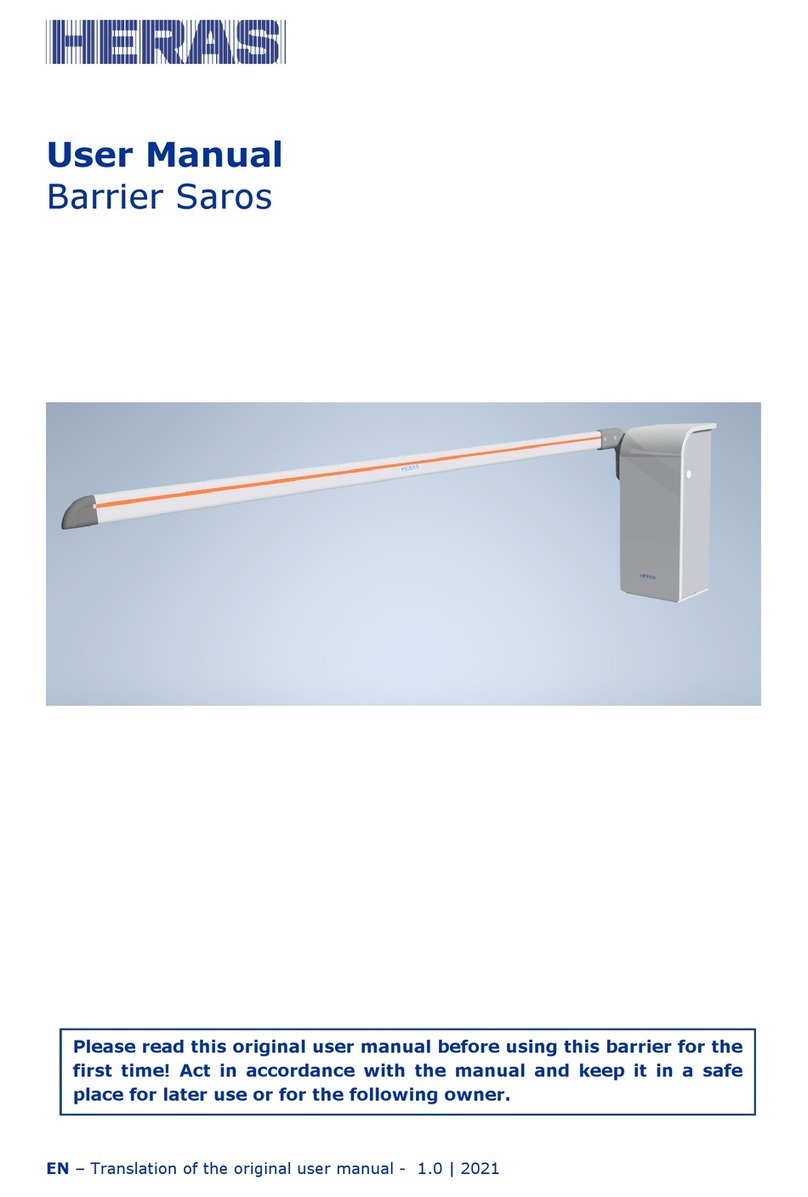
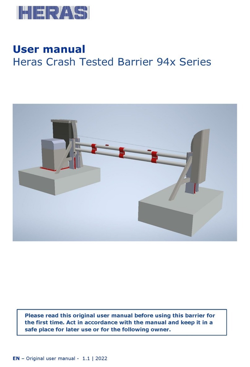
Heras 94 Series User manual

EN - Original User Manual - 1.0 | 2019
User Manual
Heras Crash Tested Barrier 94x Series
Please read this original user manual before using this barrier for the rst
time. Act in accordance with the manual and keep it in a safe place for later
use or for the following owner.

2
EN - Original User Manual - 1.0 | 2019

EN - Original User Manual - 1.0 | 2019
FOREWORD........................................................................................ 4
1 PREFACE................................................................................. 6
1.1 MANUFACTURER / SUPPLIER.................................................. 6
1.2 SERVICE / MAINTENANCE...................................................... 6
1.3 DEFINITIONS: USER / OPERATOR / ENGINEER......................... 6
1.4 PRESCRIBED USE / APPLICATION........................................... 7
1.5 CONFORMITY WITH EUROPEAN DIRECTIVES............................ 7
1.6 ELECTRICAL CONNECTIONS................................................... 7
1.7 DELIVERY............................................................................ 7
2 SAFETY................................................................................... 8
2.1 EXPLANATION OF THE SYMBOLS............................................. 8
2.2 GENERAL SAFETY INSTRUCTIONS........................................... 8
2.3 SAFETY PROVISIONS............................................................. 9
2.4 INTENDED USE.................................................................... 9
2.5 SAFETY DURING USE............................................................ 9
2.6 SAFETY DURING MAINTENANCE, INSTALLATION AND
DISASSEMBLY...................................................................... 10
3 OPERATION............................................................................ 11
3.1 OPERATING GUIDELINES....................................................... 11
3.2 OPENING/CLOSING BARRIER - NORMAL USE............................ 11
3.3 AUTO-CLOSE TIMER.............................................................. 12
3.4 MANUAL RELEASE................................................................. 12
4 EQUIPMENT DETAILS.............................................................. 13
4.1 OVERVIEW.......................................................................... 13
4.2 VARIATIONS........................................................................ 15
4.3 LZR-H100............................................................................ 15
4.4 LOOP SAFETY DETECTORS..................................................... 16
4.5 TRAFFIC LIGHTS/BEACONS (OPTIONAL).................................. 16
5 TECHNICAL DETAILS............................................................... 17
5.1 INTRODUCTION................................................................... 17
5.2 CONTROL PANEL.................................................................. 17
5.3 PROGRAMMABLE CONTROLLER............................................... 18
5.4 SWITCH MODE POWER SUPPLY UNIT....................................... 18
5.5 MECHANICAL ARRANGEMENT AND DRIVE OPERATION............... 18
5.6 ELECTRICAL LIMITS.............................................................. 19
5.7 MECHANICAL LIMITS............................................................. 19
5.8 TEMPERATURE KITS.............................................................. 19
CONTENTS
3

4
EN - Original User Manual - 1.0 | 2019
6CONTROL LOGICS.................................................................... 20
6.1 SELECTING CONTROL LOGICS................................................ 20
6.2 AUTOMATICLOGIC................................................................ 21
6.3 HOLD TO RUN LOGIC............................................................ 21
7 MAINTENANCE INSTRUCTIONS.............................................. 22
7.1 CLEANING........................................................................... 22
7.2 MAINTENANCE TASKS........................................................... 23
8DECOMMISSIONING AND REMOVAL........................................ 23
9 ASSEMBLIES........................................................................... 24
9.1 GENERAL BARRIER ASSEMBLY................................................ 24
9.2 CABINET ASSEMBLY.............................................................. 24
9.3 ASSEMBLY PARTS LIST.......................................................... 25
9.4 TECHNICAL INFORMATION.................................................... 26
10 APPENDIX.............................................................................. 27
10.1 DECLARATION OF PERFORMANCE........................................... 27
10.2 DECLARATION OF CONFORMITY.............................................. 29

EN - Original User Manual - 1.0 | 2019 5
FOREWORD
This manual provides information on the operation and maintenance of the 94x
range of barriers. A separate manual is provided for installation. Although every
eort has been made to ensure that the information contained within this manual
is correct at the time of issue, no responsibility is accepted for any loss or damage
arising from incorrect information.
This manual forms no part whatsoever of any contract or agreement between Heras
and others. In no circumstances will Heras be responsible or liable for any costs,
damage or injury whatsoever arising from the use of this Manual.
Should the barrier be tampered with and/or any non-approved equipment is tted
to the barrier then any warranty will be considered void.
The Copyright of this Manual remains the property of Heras at all times. This
Manual may not be reproduced by any means without prior written permission from
Heras.

EN - Original User Manual - 1.0 | 2019 6
1 PREFACE
1.1 MANUFACTURER / SUPPLIER
Manufacturer: Heras UK
33 Stakehill Industrial Estate
Middleton
Manchester
M24 2RW
United Kingdom
www.heras.co.uk
Technical Construction File: Heras Middleton T&I Department
1.2 SERVICE / MAINTENANCE
In the event of problems, failures or questions telephone contacts are as follows:
Heras UK +44(0) 1302 364 551
Heras Netherlands +31(0)499 551 255
Heras Germany +49(0) 1805 437277
Heras France +33(0) 3 88 067 000
Heras Norway +47(-) 22 900 555
Heras Sweden +46(0) 77 1506050
1.3 DEFINITIONS: USER / OPERATOR / ENGINEER
User: Anyone using the barrier.
Operator: A user who is familiar with all safety aspects dealt with in this manual.
Operators are not allowed to carry out any installation work on the
barrier unless explicitly specied.
Engineer: The engineer is a Heras tter (or an engineer employed by the
customer who has been given explicit permission in writing from
Heras) who is qualied to perform technical interventions on the
barrier.

7
EN - Original User Manual - 1.0 | 2019
1.4 PRESCRIBED USE / APPLICATION
Only the correct installation and maintenance by an authorised/qualied company
or person in agreement with the user manual, logbook, check lists and maintenance
lists can ensure the safe operation of the system.
A qualied person is, according to EN 12635, a person who has the required
training, qualied knowledge and practical experience required to install, test and
maintain a sliding barrier system correctly and safely.
1.5 CONFORMITY WITH EUROPEAN DIRECTIVES
The installation complies with the following EU Directives/ regulations:
2006/42/ EC Machine Directive
2014/30 EU EMC Directive (electromagnetic compatibility)
305/2011 EC Construction Product Regulation
The design and production has been executed compliant with the applicable product
standard EN 13241 and the underlying standards EN 12604, EN 12605, EN 12453,
EN 12445, EN 12978 and 12635.
A Declaration of Conformity (DoC) and Declaration of Performance (DoP) are
obligatory for this product. The DoC is included in the Appendix.
1.6 DELIVERY
The barrier, drive and control unit must be installed by a tter or an engineer who
also connects and programs any accessories. The barrier control unit is adjusted to
the options/accessories agreed with the user. The relevant options are laid down
during hand-over.
Optional accessories can be installed afterwards, simply contact the supplier.
Barrier are always delivered fully tested.
1.7 ELECTRICAL CONNECTIONS
Electrical connections must be made compliant with the supplied wiring diagram.
The system must be correctly earthed (Protective grounding in accordance with DIN
VDE).
Because EMC-related suppression components can leak current to the earth cable,
it is advisable that you do not protect the control unit with a Residual Current
Device. When switching on the system, a high starting current can be generated
due to the charging of the intermediate circuit.
If after measurement during commissioning it appears that the leakage current
exceeds the permitted 3.5 mA, an additional grounding, in accordance with EN
60335-1 and IEC 30364-5-54, must be provided. Measurement is made according
to EN 60335-2-103. Consult your installer for this.
Take into account good shielding, for example an automatic circuit breaker 16A B
characteristic.
Ensure that the feeder cables are not carrying power during commissioning.

EN - Original User Manual - 1.0 | 2019 8
2 SAFETY
2.1 EXPLANATION OF THE SYMBOLS
Caution: To prevent personal injury, observe the safety instructions below.
Note: To prevent material damage, observe the safety instruction below.
Information: Followed by further information or a reference to other documents.
Warning: Risk of limbs getting crushed
Warning: Risk of injury to hands by gear wheels
2.2 GENERAL SAFETY INSTRUCTIONS
• The operator must read the entire user manual before the barrier is used for
the rst time. The instructions stated in the user manual must be observed
and complied with. All other forms of use can cause unexpected hazards and
are forbidden. If the meaning of any part of these instructions is not clear,
contact the supplier before using the equipment.
• It is forbidden to apply the drive unit to barriers other than those stated in
this manual, without Heras’ permission.
• Applying a third-party drive unit and/or safety device may aect safety
compliance and will invalidate the CE mark.
• The barrier must only be put into use if all safety facilities are in place and
connected, and work properly.
• All faults which might present a source of danger to the user or to third
persons must be eliminated immediately.
• All warnings and safety notices on the equipment must be in place and
clearly legible at all times.
• All alterations or extensions to the barrier must be carried out by qualied
engineers using parts which the manufacturer has dened as suitable for
such alterations or extensions. Any failure to comply with these instructions
will be considered as non-compliant behaviour and will invalidate the
manufacturer’s guarantee, as a result of which the risk entirely transfers to
the user.
• Improper usage or servicing or ignoring the operating instructions can be a
source of danger for persons, and/or result in material damage.
• This manual must always be available at the operating location. This manual
must be read thoroughly and applied by all persons who are in charge of the
operation, maintenance and restoration of the controls.

9
EN - Original User Manual - 1.0 | 2019
2.3 SAFETY PROVISIONS
• To protect people and goods from injury or damage, the barrier is tted
with safety provisions including a sensitive protective device that prevents
contact with the moving beam.
• The safety provisions serve as emergency provisions that immediately stop
the movement of the barrier. It is forbidden to use these provisions to stop
the barrier normally.
• For a barrier with hold-to-run control, the above-mentioned safety
provisions are not necessary and will therefore not be standard provisions.
With this type of operation, the barrier stops immediately as soon as the
switch is released.
2.4 INTENDED USE
The barrier is an entrance control product designed and intended to be used as an
access control point to a specic plot, premises or site. The barrier is designed to
protect the site against road-based vehicular impacts. The barrier is intended for
both industrial and private use.
The barrier is not to be used to lift any loads other than permitted accessories. The
barrier should not be climbed upon for any reason. The barrier should not be used
in any other way than described in this manual.
The barrier drive and control unit is adjusted to the options agreed with the user.
The relevant options are laid down during hand-over.
Carefully read this user manual before operating the barrier. You must always
be familiar with the operating mode the barrier is in.
2.5 SAFETY DURING USE
Children or people with a disability must not operate the barrier. Parents must
supervise their children to prevent them playing with the barrier.
PARENTS ARE RESPONSIBLE FOR THEIR CHILDREN
• Keep a safe distance from the moving barrier. Warning icons to this eect
have been installed in various locations.
• Only pass through the barrier when it is completely open.
• The safety devices serve as emergency facilities to immediately stop and reverse
the barrier movement. Using them as a regular barrier stop feature is not
allowed.
• When hold-to-run-control is employed, the barrier must only be operated if
it can be seen completely, directly and in real-time. Operation must be via a
permanently installed operating device, for instance a key switch or push button.
This operating device must be located in such a way that the operator’s position
is safe. The barrier must stop immediately when the button or key is released.
Other operating devices are not allowed.
• The barrier must be able to move freely without there being obstacles in the
barrier opening passage or anywhere else on the moving trajectory of the

EN - Original User Manual - 1.0 | 2019 10
barrier. Do not stick any objects through, over or under the barrier which might
block the barrier.
• In windy conditions the barrier arm can move back and forth in the open
position or during opening. This has no adverse consequences on the
construction.
• Climbing the barrier is strictly forbidden as people climbing the barrier could be
hurt if the barrier is started unexpectedly.
• The safety device is not active during opening.
• Do not stick any objects through, over or under the barrier which might block
the barrier.
• Do not place any obstacles in the opening.
• Always lock the drive unit cabinet during use.
2.6 SAFETY DURING INSTALLATION, MAINTENANCE AND DISASSEMBLY
• When work is carried out or while cleaning the barrier, the power supply to the
system must be switched o and it must be ensured that it cannot be switched
on unexpectedly. To isolate the barrier locally, switch o the unit using the MCB
power isolator located at the bottom right hand side of the barrier cabinet.
• Maintenance should not be performed on the barrier until it has been isolated at
the main consumer unit and locked in the OFF position. Heras recommends that
a permit to work system be in place with remote isolation being carried out prior
to working on the unit.
• Use the necessary personal safety equipment.
• The EN 13241 and EN 12453 standards must be taken into consideration during
installation. To achieve a good safety level, both the above standards and the
national regulations must be taken into account in non-EC countries.
• If the barrier is damaged, always contact the supplier for an inspection.

11
EN - Original User Manual - 1.0 | 2019
3 OPERATION
3.1 OPERATING GUIDELINES
The barrier operator should always carry out the following prior to operation:
• Ensure no pedestrians in the vicinity prior to operating the barrier.
• Use signage and/or intercoms where possible to advise drivers not to proceed
until the barrier has stopped moving, the barrier is fully raised and the trac
light is green (where installed).
• Advise drivers not to tail-gate either on entry or exit.
• Close the barrier if obstacles are present within the travel of the barrier’s arm.
• In the event of accident or breakdown, if a blockage is likely to occur, follow the
instructions detailed in section 3.4.
3.2 OPENING/CLOSING BARRIER - NORMAL USE
The barrier can be operated using pulse operation, for instance via a button or key
switch. The location of the operating device depends on the customer’s choice or
the operating mode. The generic operating controls are as follows:
OPEN: Press the “Open” button. The barrier opens to the end position.
The fully open position is approx. 85º.
During opening the safety device is not active.
CLOSE: Press the “Close” button. The barrier closes completely.
STOP: Press the “Stop” button.
(optional): The barrier will stop immediately, irrespective of its direction of travel.
To restart the barrier press OPEN or CLOSE.

EN - Original User Manual - 1.0 | 2019 12
3.3 AUTO-CLOSE TIMER
When the barrier system is set to ‘automatic logic’ and an open signal is received
from either a push button or card reader the barrier will open, should no vehicle
drive through the barrier then the barrier arm will re-close after a set time. The
default time is 30 seconds from when the barrier is fully open.
3.4 MANUAL RELEASE
Never attempt to raise/lower the barrier by pushing the barrier arm. This can
cause severe damage. Ensure whenever lowering the barrier that the area
beneath is free from people or any other obstacle. To manually operate the
barrier, refer to the image below and carry out the following:
• Isolate power using the MCB power isolator located at the bottom right hand
side of the barrier cabinet
• Turn either raise/lower nipple fully clockwise depending on desired direction of
travel
• Ensure only the nipple designating desired direction of travel is turned
• Locate the hand pump handle, which is always permanently stored below the
door, and insert the handle into receptor
• Apply lateral movements to pump handle. The barrier may take a number of
applications to begin movement as pressure builds
• Ensure both nipples are released before re-powering
In case of manual release the barrier should only be raised/lowered through
use of the hand pump. Under no circumstance raise or lower the barrier by
directly moving the barrier arm.
Raise
nipple
Lower
nipple
Hand pump
receptor
MCB power
isolator
Hand pump
handle
Manual release controls

13
EN - Original User Manual - 1.0 | 2019
4 EQUIPMENT DETAILS
4.1 OVERVIEW
The Heras 94x series is a range of impact tested dual beam vehicle barriers
used to control vehicular access to high security controlled areas. The dual
beams integrated with the unique bre system provide formidable mechanical
characteristics and greater energy absorption on impact than a conventional barrier
system. The barrier is applicable for perimeter and interior site use and can operate
both indoors and outdoors. Various beam lengths are available from up to 6 metres
clear opening. The barrier is designed to operate up to 12 beaufort (Wind Class: 3
up to 6 metres)
Cabinet
Barrier end stanchion
Beam assemblyEnd beam
stanchion
View of left-handed barrier

EN - Original User Manual - 1.0 | 2019 14
942 Test
943 Test (4 m)
943 Test (6 m)

15
EN - Original User Manual - 1.0 | 2019
4.2 VARIATIONS
The 94x series is a range of side-acting barriers available in either left or right hand
handing. The handing of the barrier is determined by looking at the barrier arm
from the rear of the barrier cabinet. The side the barrier arm is in relation to the
barrier cabinet determines the handing of the barrier.
Left hand barrier
(View from behind
cabinet)
Right hand barrier
(View from behind
cabinet)
Plan view of right hand barrier
Plan view of left hand barrier
DIRECTION OF ATTACK
4.3 LZR-H100
The 94x range integrates the BEA LZR-H100 laser safety sensor to ensure
smoothness in operation as well as total compliance with all applicable safety
standards.
Manuals for the LZR-H100 will be made available as part of commissioning detailing
the general specications operation and maintenance information for this device.
Refer to the installation manual of this product for information on where the laser
is mounted in relation to the barrier. Site specic drawings should also be issued
as part of the installation process. The barrier is installed in accordance with EN
12453.

EN - Original User Manual - 1.0 | 2019 16
The device should only be congured by an approved Heras installer. Altering
the settings after installation will make operation of the barrier unsafe and will
invalidate the CE marking.
Laser sweep
emission
Laser sweep
reception
LED signals
Screws for
position lock
Connector
Protection
cover
Adjustable
bracket
Notch for tilt
angle adjustment
The LZR-H100 is a motion and presence detecting device which is congured to
detect applicable objects in the detection zone.
The sensor and detection eld position are key to the appropriate function of the
barrier. The sensor has to learn a reference as part of installation. Appropriate
positioning should be determined and issued as part of site specic drawings and
issued as part of the installation process.
Consult the manual user manual of the LZR-H100 for troubleshooting.
4.4 LOOP SAFETY DETECTORS
Loop safety detectors must be installed. This electromagnetic communication
system detects vehicles passing through or arriving at a designated area or loop.
The behaviour of the loop safety detector depends on the chosen control logic,
refer to section 6 for additional information.
The loop safety detector is limited to the detection of road vehicles, and does not
including motor bikes, pedestrians or equestrians.
4.5 TRAFFIC LIGHTS/BEACONS (OPTIONAL)
Signal lights or beacons can be provided to indicate the position status of the
barrier. Passage across the barrier is only permitted when the green light shows.
Beacons ensure additional attention from drivers to maximise safety.

17
EN - Original User Manual - 1.0 | 2019
5 TECHNICAL DETAILS
5.1 INTRODUCTION
This section provides basic information about the equipment used in the
installation, particularly as an aid to fault diagnosis and/or reporting in the event of
a system failure.
5.2 CONTROL PANEL
The control panel for the barrier incorporates a PLC, a switch-mode power supply
unit and a set of eld termination connectors/terminals.
The connection details and layout of the control panel are shown below. Part codes
are shown in brackets.
Switch mode
PSU 24VDC 30W
(001190)
Field terminal
connectors
1-12
Free exit/open
loop detector
(000334)
Inverter motor
speed controller
(001274)
PLC controller
(001321)
Field terminal
connectors
13-24
Safety/close
loop detectors
(000334)
View of Control Panel with Terminal Details

EN - Original User Manual - 1.0 | 2019 18
5.3 PROGRAMMABLE CONTROLLER
The control panel for the barrier incorporates a programmable controller as the
main control component. This includes input terminals and output terminals. All
inputs activate when + 24 Volts is fed into the relevant input. The outputs are relay
contacts, some of which have a common inbound contact.
5.4 SWITCH MODE POWER SUPPLY UNIT (PSU)
The control panel has a 110-230VAC 50/60Hz to 24VDC 30W switch mode PSU
which provides the low voltage for the controls.
5.5 MECHANICAL ARRANGEMENT AND DRIVE OPERATION
The arm is made from extruded aluminium sections. The yoke is manufactured
using mild steel and the power transmission through the yoke is via the linear
hydraulic cylinder. Heavy duty bearings ensure both trouble free operation and
minimum friction from the rotary motion of the yoke shaft. All bearings must be
greased on installation and regularly greased as part of maintenance.
The interior of the cabinet is shown below. Part codes are shown in brackets.
Electrical
hydraulic power
unit assembly
(001345)
Directional
solenoids
Control panel
Barrier electrical
isolator assy.
Internal cabinet view

19
EN - Original User Manual - 1.0 | 2019
5.6 ELECTRICAL LIMITS
The travel of the barrier is governed by proximity limit switches.
5.7 MECHANICAL LIMITS
The barrier also has mechanical limits for each direction of travel. The mechanical
limits are set in order that there is a 5 mm gap between the bolt heads and the
quadrant at both the fully lowered and fully raised positions.
5.8 TEMPERATURE KITS
In climates with extreme temperatures, the addition of a heater and/or cooler kit
will be necessary to ensure the motor functions optimally. If temperatures regularly
fall below 0°C, a low temperature modication kit may be required. If temperatures
regularly exceed 40°C, a high temperature modication kit may be required.
Systems operating in such temperatures without the recommended temperature
kits may have operational issues.
Heater Incl. Thermostat
(001756)
Thermostat (High
Temperature Kit)
(001757)
Fan
(001758)
Door for high
temperature kit

EN - Original User Manual - 1.0 | 2019 20
6 CONTROL LOGICS
6.1 SELECTING CONTROL LOGICS
To select logic simply turn the two potentiometers to the relevant positions as
shown below:
Potentiometers
Com Port
Automatic Logic
Turn top potentiometer fully clockwise and bottom potentiometer fully counter-
clockwise.
Hold to Run(Open/Raise and Close/Lower)
Turn top potentiometer fully counter-clockwise and bottom potentiometer fully
clockwise.
Other manuals for 94 Series
1
This manual suits for next models
8
Table of contents
Other Heras Control System manuals
Popular Control System manuals by other brands

Aqua Control
Aqua Control CL2 Deluxe 1,6 l/h manual

Securakey
Securakey Radio Key RK-600 Installation & operating guide

TECH FASS
TECH FASS APS mini MDEM 31 user guide

Spraying Systems
Spraying Systems 1550+ AutoJet quick start guide

CleaverBrooks
CleaverBrooks PCS140e.1 Installation operation user manual

Leadshine Technology
Leadshine Technology DMC5400 Hardware manual