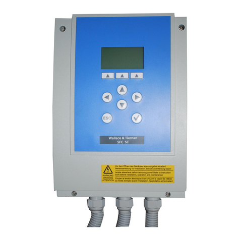
Evoqua WALLACE & TIERNAN SFC SC Operation instructions

WALLACE & TIERNAN®MEASURING AND CONTROL
SYSTEM
SFC SC
from version V:3.06
INSTRUCTION MANUAL

2 WT.050.590.020.DE.IM.0719
SFC SC
Please note
Original manual!

SFC SC Contents
3
Contents
1. Introduction 5
1.1 Documentation 5
1.2 Conventions 6
2. Safety 7
2.1 Intended use 7
2.2 General safety instructions 7
2.3 Warranty conditions 8
2.4 Specific Operating Phases 9
2.5 Notes on Special Dangers 10
3. Description 11
3.1 Versions 11
3.2 Technical Data 12
3.3 Scope of supply 14
3.4 Description 15
4. Functions 19
4.1 General 19
4.2 mA input on the A&C board 20
4.3 Outputs 21
4.4 Controller outputs 25
4.5 Parameters and settings 27
4.6 Serial port for firmware updates 29
4.7 Actuator feedback 29
4.8 Digital inputs 30
4.9 Unit configuration 30

4 WT.050.590.020.DE.IM.0719
Contents SFC SC
5. Installation 31
5.1 Transport and storage 31
5.2 Installation 32
5.3 Commissioning 36
5.4 System shut down 41
6. Operation 43
6.1 Display and operator controls 43
6.2 Notes on operation 47
6.3 Menu structure 49
6.4 Errors and remedies 63
7. Maintenance 65
7.1 Changing the fuse on the A&C board 65
8. Complete units and spare parts 67
9. Wiring Diagrams 69
10. Certificats 73
11. Settings Table 77
12. Index 79

SFC SC Introduction
1.
5
1. Introduction
1.1 Documentation
1.1.1 Target groups
This instruction manual provides the information for installation,
operating and maintenance personnel. It is required for operation
and maintenance of the unit.
This instruction manual is intended for the operating personnel. It
contains important information for safe, reliable, trouble-free and
economical operation of the unit. Observance of this information
helps to prevent danger, lowers repair costs, reduces down-times,
and also increases the reliability and service life of the unit.
The chapters on installation and maintenance are solely provided
for trained service personnel. These sections contain important
information on the installation, configuration and commissioning of
the unit as well as information on its repair.
All persons working with the unit must have read and understood
the operating instructions, in particular, the safety instructions it
contains.
Please consult the table of contents and the index to find the
information you require quickly.

6 WT.050.590.020.DE.IM.0719
Introduction SFC SC
1.
1.2 Conventions
Please note
This operating manual contains a number of notes with different
priorities, which are marked with symbols.
Pictogram Note Meaning
Danger!
Immediate danger to life and limb! If
the situation is not handled properly,
death or serious injury may be the
result.
Warning!
Danger to life and limb! If the
situation is not handled properly,
death or serious injury may be the
result.
Attention!
If this warning is not observed,
medium or slight injury or damage to
the equipment may the result.
Warning!
Electrical hazard.
Please
note
These notes facilitate work with the
unit / system.

SFC SC Safety
2.
7
2. Safety
2.1 Intended use
The SFC SC is intended exclusively for controlling the treatment of
waste water, potable water and industrial water.
The operational safety of the unit is only guaranteed if it is used in
accordance with its intended application. The unit may only be
used for the purpose defined in the order and under the operating
conditions indicated in the technical specifications.
Compliance with the intended use also includes reading this
operating manual and observing all the instructions it contains.
Furthermore, all inspection and maintenance work must be
performed at the prescribed intervals.
The operator bears full and sole responsibility if this unit is put to
any use which does not comply strictly and exclusively with this
intended use.
2.2 General safety instructions
Evoqua Water Technologies GmbH attaches great importance to
ensuring that work on its system is always perfectly safe. This was
already taken into account in the design of the system, by the
integration of safety features.
Safety instructions The safety instructions in this documentation must always be
observed. These do not affect the validity of any additional national
or company safety instructions.
Safety instructions printed on
the Unit All safety instructions attached to the system itself must be
observed. They must always be complete and easily legible.

8 WT.050.590.020.DE.IM.0719
Safety SFC SC
2.
Technical standard The system or unit has been constructed in accordance with state-
of-the-art technology and the accepted safety regulations.
However, in the event of the system or unit being used by persons
who have not been adequately instructed, risks to life and limb of
such persons or third parties and damage to the system or unit
itself or to other property cannot be ruled out. Work not described
in this operating manual may only be performed by authorized
personnel.
Personnel The operator of the system must ensure that only authorized and
qualified specialized personnel are permitted to work with and on
the unit within their defined scope of authority. „Authorized
specialists“ are trained technicians employed by the operator, by
Evoqua, or, if applicable, the service partner. Only qualified
electricians may perform work on electrical components.
Spare parts / components Trouble-free operation of the system is only guaranteed if original
spare parts and components are used in precisely the combination
described in this operating manual. Failure to observe this
instruction may incur the risk of malfunction or damage to the
system.
Modifications and extensions Never attempt to perform any modifications, extensions or
conversions on the unit that could have an adverse affect on
safety.
Electrical power During normal operation, the control unit must remain closed.
Before starting any assembly, inspection, maintenance, or repair
work, the system must be switched OFF using the emergency stop
switch and the switch must be secured against reactivation.
Connect all cables in accordance with the wiring diagram.
Waste disposal Ensure safe and environmentally-friendly disposal of agents and
replaced parts.
2.3 Warranty conditions
The following must be observed for compliance with warranty
conditions:
• Installation, commissioning by Evoqua technicians or
trained and authorized specialized personnel, e.g. of
contracted companies
• Intended use
• Observation of the operational parameters and settings.
• The unit may only be operated by trained personnel.

SFC SC Safety
2.
9
• An operating log book must be kept (only in the public
sector).
• The unit must not be exposed to frost.
• Maintenance work must be executed
• Use of original spare parts
If any of the above conditions are not met, the warranty is void.
2.4 Specific Operating Phases
Normal operation Never employ any working methods which could affect safety!
Only run the unit when the housing is closed!
Inspect the unit at least once daily for externally visible damage
and faults! Inform the responsible person/authority immediately of
any detected changes (including any changes in the operating
performance)!
In the event of malfunctions, always switch the unit off
immediately! Have malfunctions remedied immediately!
Installation and
maintenance Always perform installation or maintenance work in accordance
with this operating manual or the technical documentation for
installed unit components!
Secure the unit against activation during installation and
maintenance work!
Always retighten released screw connections!
Never use corrosive cleaning agents!
Use only a damp cloth to clean the unit.
Ensure safe disposal of agents and replaced parts in accordance
with environmental regulations!

10 WT.050.590.020.DE.IM.0719
Safety SFC SC
2.
2.5 Notes on Special Dangers
Electrical power Only use original fuses with the prescribed current rating! In the
event of a fault in the electrical power supply, switch the unit off
immediately!
Only qualified electricians or trained personnel supervised by a
qualified electrician are permitted to perform any work on electrical
components in accordance with valid electro-technical regulations.
If stipulated, disconnect all parts of the device from the power
supply before performing any inspection, maintenance or repair
work. Then first test the disconnected components to ensure they
do not carry any voltage.
Inspect/check the electrical system of the unit regularly. Remedy
any faults immediately!
Connect disconnected cables in accordance with the wiring
diagram!
Agents und
chemicals When handling agents and chemical substances always observe
the safety regulations valid for each product!
Always remove leaked agents immediately with a suitable binder
or wipe up with a cloth. Danger of slipping!
Always collect and dispose of agents or used cleaning material
separately and in accordance with valid national regulations!

SFC SC Description
3.
11
3. Description
3.1 Versions
The SFC SC is available as a control cabinet unit or as a wall unit.
It has the following inputs and outputs:
•2 relays
• 1 x mA input
• 1x feedback input
• 2x digital input
• 1x mA output
• 1x interface for firmware updates

12 WT.050.590.020.DE.IM.0719
Description SFC SC
3.
3.2 Technical Data
3.2.1 Electronic module SFC SC
Housing
Electronics
Caution!
Do not use the device in measuring categories II, III and IV.
Dimensions (WxHxD) 185 x 265 x 145 mm
Weight approx. 2.5 kg
Protection type IP 66
Mains connection
100 – 240 V AC ± 10%, 50-60 Hz, 15 W, Fuse 1A (T) Type:
TR5
24 V DC ± 20%, 15 W, Fuse 1 A (T) Type: TR5
Insulation
Overvoltage category 2
Contamination level 2
Measuring category I
Operating conditions
Ambient temperature 0 – 50 °C
Humidity < 80 %
Environment No direct sunlight
Atmospheric pressure 75 – 106 kPa
Max. altitude 2000 m
Storage temperature -20 – +70 °C
Noise emission <45 dB

SFC SC Description
3.
13
Interfaces
Display and operating unit
Relay outputs
Digital inputs
2x inputs for voltage-free contact (< 100 Ohm) power supply
via SFC SC (12 V)
DI 1: Sample water monitoring / freely selectable in menu
DI 2: Freely selectable in menu
Measurement inputs
1 x Feedback input
Positioner position feedback
Potentiometer 1 kOhm or 5 kOhm, 0 – 1 V, 0 – 20 mA
(selectable using DIP switches)
1x mA input for flow rate 0 – 20 mA/4 – 20 mA
In SFC units with a 24 V supply voltage this input is not
electrically isolated from the 24 V DC supply voltage.
1x RS232 for firmware updates (not galvanically isolated)
1 x Operating panel with 9 keys
1 x Graphic display:
• Resolution 128 x 64 pixels
• white background illumination
2 relay outputs (2 two-way switches)
Switching values 5 A, 250 V AC, 1250 VA max
5 A, 220 V DC, 150 W max
UL/CSA-rating 5 A, 1/6 HP 125, 250 V AC
5 A, 30 V DC, 30 W max
1 A, 30 V DC - 0.24 A, 125 V DC

14 WT.050.590.020.DE.IM.0719
Description SFC SC
3.
mA output
3.3 Scope of supply
Please note
You will find the order numbers under 8. “Complete units and
spare parts”.
3.3.1 Standard
Depending on the individual order, the scope of supply includes
the following:
Electronic module SFC SC
incl. accessories set and mounting set, comprising:
4 screws (Ø = 5 mm)
4 dowels (Ø = 8 mm)
4 washers
3 multiple seal inserts 2 x 6 mm
3 multiple seal inserts 4 x 5 mm
3 reducing seal rings Ø = 8 mm
4 bolts for multiple seal inserts 5 mm
2 bolts for multiple seal inserts 6 mm
1x mA output (freely configurable):
• Output 0/4 – 20 mA
• Accuracy < 0.5% FS
• Load max. 500 Ohm
• Temperature drift max. 0.2% / 10°C
• Load monitoring
• Electrically isolated up to 50 V to earth

SFC SC Description
3.
15
3.4 Description
3.4.1 Versions
SFC SC There are two voltage versions of the SFC SC.
• 100 – 240 V AC
• 24 V DC
3.4.2 Design
Overall design The SFC SC modules can be installed on a top-hat rail or using
wall fastening brackets.
Picture 1 Electronic module SFC SC

16 WT.050.590.020.DE.IM.0719
Description SFC SC
3.
Electronic module SFC SC The electronics module SFC SC consists of a plastic housing (C)
with a removable cover.
The housing contains:
• A&C board (A)
• the cable glands (B)
Picture 2 SFC SC Basic
A A&C Board
B Cable glands
C Housing
A
B
C

SFC SC Description
3.
17
The following are integrated into the cover:
• Front panel board with graphic display (B)
• Insertable strips (C))
Picture 3 SFC SC Operating front (rear)
A Housing cover
B Front panel board
C Insertable strips
A
B
C

18 WT.050.590.020.DE.IM.0719
Description SFC SC
3.

SFC SC Functions
4.
19
4. Functions
4.1 General
The SFC SC is a specialised control unit for quantity-proportional
dosing of chemicals used in potable water processing as well as
for industrial process water and waste water treatment.
Typical applications:
• Quantity-proportional dosing of disinfectants (ratio control)
• Quantity-proportional dosing of disinfectants with linearization
of the actuator (with positioner)
The integrated graphic display displays the following:
• Measured values for flow rate
•Mode
• Bar chart representation of the feed rate
• Display of the dosing factor and feed rate
• Description of customized measuring points
The menus are easy to use, displayed in plain text and are
selected using softkeys.
An mA output is provided for connection to a visualtisation system.
Overall Function The available signal inputs are:
• External mA signal for flow rate measurement
• Actuator feedback
• 2 digital inputs
The feed rate is determined on the basis of the flow rate signal and
a user-configurable feed factor and output via an mA output or a
relay.

20 WT.050.590.020.DE.IM.0719
Functions SFC SC
4.
Controller outputs The systems has outputs for positioners, dosing pumps, pulse
pumps, and a continuous mA output.
Safety functions Depending on the configuration, the following safety functions
are integrated in the control unit:
• Safety shutdown if the feed container signal indicates it is
empty
• Dosing time delay (D1)
• External stop with digital input
• "Positioner closed" function in the event of a power failure
(only if positioner has external power supply)
• Password protection in one level
Configuration switch-over The SFC SC gives the option of either saving internally or loading
all necessary operating parameters as a configuration. A
maximum of two configurations are possible.
A digital input can be used to switch between the two
configurations.
4.2 mA input on the A&C board
There is one integrated mA input on the A&C board.
mA input 1 This is used for recording the flow rate signal as 0 – 20 mA or
4 – 20 mA signal.
The input signal can be freely scaled in the menu (see Inputs/
Outputs menu).
Table of contents
Other Evoqua Control System manuals
Popular Control System manuals by other brands
Invacare
Invacare LiNX Service manual
Fasel Elektronik
Fasel Elektronik FCU-EXT-APP-CONTROL Installation
Dynamite
Dynamite Li-Po Glow Driver instructions
Watts
Watts OneFlow OFTWH-R Installation and operation manual
Fagor
Fagor CNC 8060 Users Quick Reference

Bosch
Bosch FHP UPM I Installation and operation manual
