EVR Electronics GSM-THERMO CX36 Instruction manual

ROOM THERMOSTAT
WITH GSM MODULE
GSM-THERMO CX36
CLIMA CONTROL
Manual of use
and installation

Copyright©2015 EVR Electronics.
All right reserved. Print only for private use.
www.gsmcontrol.biz
2
Index
1. Information pag. 3
1.1 Notice pag. 3
1.2 Introduction pag. 3
1.3 Rules for sending SMS pag. 4
1.4 Preparation of the SIM pag. 4
2. Installation pag. 4
2.1 Electrical connections pag. 6
2.2 Pinout pag. 7
2.3 Panel Description pag. 7
3. SMS of Use pag. 8
3.1 Command C (Comfort Function) - Activation / Deactivation Comfort pag. 8
3.2 Command R (Read) - Temperature reading pag. 9
4. Programming SMS pag. 9
4.1 Command T (Set Temperature) - Temperature setting Comfort pag. 9
4.2 Command U (Users) - Programming telephone numbers Users pag. 10
5. Utility SMS pag. 11
5.1 Command TA (Alarm Temperature) - Temperature setting alarm pag. 11
5.2 Command EC (Echo) - Enable / Disable Echo SMS pag. 12
5.3 Command F (firmware) - Read firmware version pag. 12
5.4 Command P (Password) - Programming password pag. 12
5.5 External antenna and Command N (Network) - Check Network pag. 13
6. Commands list pag. 14
7. Safety Instructions pag. 15
8. Technical features pag. 16
9. Warranty pag. 16
9.1 Technical support pag. 16

3
Copyright©2015 EVR Electronics.
All right reserved. Print only for private use. www.gsmcontrol.biz
This manual contains important information for using and installing the thermostat GSM CX36; read the manual
before using the device. The warranty does not comply with the instructions provided in this manual. We can not be
held responsible for property damage or injury due to non-application of the safety instructions.
1. Information
1.1 Notice
During operation, the device can automatically generate SMS message which costs attributable only to the user.
1.2 Introduction
The thermostat GSM CX36 provides of a GSM modem, an ambient temperature sensor and a relay output (button
electro commanded).
It allows you to turn on or off a boiler, a pump, a burner or to open and close a valve in function of the measured
temperature and the set temperature. In particular, in Comfort ON, the relay closes its contact and actuates the boil-
er when the temperature of the environment is lower than the set value; vice versa, he opens the contact and stops
the boiler when the room temperature has reached the desired value.
It is connected in parallel to the existing thermostat: when you are in the home you continue to use the original ther-
mostat; however remotely set the desired temperature via SMS or telephone device.
It can also be combined to pellet stoves and boilers with remote control (in order first the checks listed in the chap-
ter Electrical Connections).
There are two modes of operation:
OFF state of comfort is disabled, the device will not operate the boiler
ON The device turns on / off the boiler as a function of temperature Comfort set
The temperature and the state can be controlled remotely:
- By sending an SMS containing the password and the command or with COFF
- Calling from a mobile device enabled
The initial programming is done by issuing commands in the form of SMS.All programming parameters of the device,
the phone numbers of users and the state of Comfort are stored in non-volatile memory device (stored either unplug
power that changing the SIM).
When power network status Comfort (ON or OFF) is restored to the condition it was in before the power failure.
To function requires a SIM of mobile telephony and a stabilized supply voltage to 12Vdc.

Copyright©2015 EVR Electronics.
All right reserved. Print only for private use.
www.gsmcontrol.biz
4
2. Installation
Set the thermostat GSM side of the original thermostat.
It 'important that the place of installation there is a good
GSM signal. The device provides an internal antenna
that is suitable for most applications. Otherwise you can
connect an external antenna with cable stylus supplied.
With a screwdriver press the tabs and remove the back
of the container.
Secure the back of the container to the wall with dow-
els.
Use flat-head screws.
Apply the tape to the metal heads of the screws to pre-
vent accidental cause short circuits on the base
address.
Keep tabs opening down.
1.3 Rules for sending SMS
Programming the device and the demand for specific operations done by sending to the thermostat (the telephone
number of the SIM card) SMS messages.
- The device has a four-digit password (initially "0000" [four zeros]); the password must be present at the beginning
of every SMS message, change the password only after becoming acquainted with the device. If you send a text
message with invalid password, the remote control does not send a reply SMS but flashes the green LED RUN 3
times.
- All SMS must be typed in capital letters.
- The mobile phone and sends text messages must also send your ID: the setting "Hide number" must not be active.
- The reply SMS is sent to the phone that sent the command.
1.4 Preparation of the SIM
Obtain an active voice SIM (no data SIM) from any supplier of GSM mobile phone except 3 (3G UMTS).
Insert the SIM in any mobile phone and disable the PIN request of the SIM. Verify that the command has been exe-
cuted: switch your phone off and on again, to verify that the phone now engage the GSM network without the need
to type any SIM unlock code. Delete any SMS messages to SIM. Clear any numbers from the SIM phonebook.
Verify that the setting "Hide number" is not active.
Remove the SIM card from the phone and install the thermostat GSM respecting its notch.
Warning: Disconnect the power supply before inserting or removing the SIM. Removing or inserting the SIM card
with the powered device will destroy the same.
5
Copyright©2015 EVR Electronics.
All right reserved. Print only for private use. www.gsmcontrol.biz
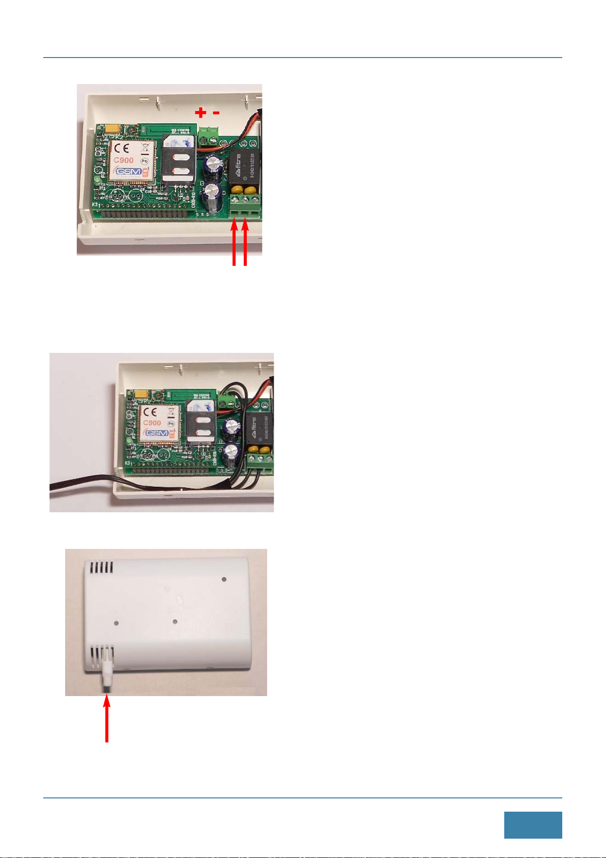
Press the cover on the base until it clicks. Place the
device with the temperature probe facing downward.
With a wire cutter to cut laterally the container so as to
allow the exit of the cables.
Accompany cables horizontally toward the notch out-
put, possibly secure them to the container with tape.
Protect the cables overlap the PCB.
Insert the SIM in its connector: push the connector to
the left, lift the cover, insert the SIM with the contacts
facing down, lower the tongue and move it to the right
until it clicks.
Apply to the terminal V + (positive) and -V (ground) and
a DC voltage of 12Vdc STABILIZED observing polarity.
Notes
- The SMA connector is mounted below, see chapter
external antenna.
TEMPERATURE
PROBE
BOILER
POWER

Copyright©2015 EVR Electronics.
All right reserved. Print only for private use.
www.gsmcontrol.biz
6
2.1 Electrical connections
Original thermostat with relay output
In case of boiler, boiler or motorized valve controlled by a thermostat (or programmable thermostat) with relay out-
put, just connect the two relay contacts thermostat GSM in parallel to the two relay contacts output of original ther-
mostat. Locally will continue to use the existing thermostat to set the desired temperature, we can remotely change
the room temperature via SMS or calls.
Connect contacts (OUT1 NO) (OUT1 C) in parallel with the relay contact of the original thermostat.
Caution: Do not remove or disconnect the thermostat preinstalled as will the frost protection or the maintenance of
a minimum temperature antifreeze.
Original thermostat via bus
Some boilers do not provide a control input but have a remote control that also performs the function of the thermo-
stat; in this case in the home we have a device that communicates through a bus to two or four wires to the boiler.
This information is shown in the manual of the boiler, and almost always the device is marked with the same name
of the manufacturer of the boiler.
Connect the two relay contacts thermostat GSM to the control input (eg. TEL) of the original thermostat; set in the
thermostat GSM Comfort a very high temperature (eg. 40 ° C) so as to always activate the relay in the ON Comfort.
Check the manual of the original thermostat which is present a control input.
Pellet boiler
Connect the two relay contacts thermostat GSM to the control input of the pellet stove; set in the thermostat GSM
Comfort a very high temperature (eg. 40 ° C) so as to always activate the relay in the ON Comfort.
Check the manual of the pellet stove which is present a remote control input, or two legs which between
them closed (short circuit), cause the ignition of the stove.
GSM
THERMOSTAT
POWER SUPPLY
12Vdc
ORIGINAL
THERMOSTAT
BOILER
INPUT
7
Copyright©2015 EVR Electronics.
All right reserved. Print only for private use. www.gsmcontrol.biz
2.2 Pinout
CODE DESCRIPTION CONNECTION
+V Power input 12Vdc (POSITIVE) Connect to a power supply with
-V Power input 12Vdc (GND) stabilized output 12Vdc min. 500mA
OUT1 NO Normally open contact Relay Output 1 At existing thermostat
OUT1 NC Normally closed contact Relay Output 1
OUT1 C Common contact Relay Output 1
* Reserved
* * **
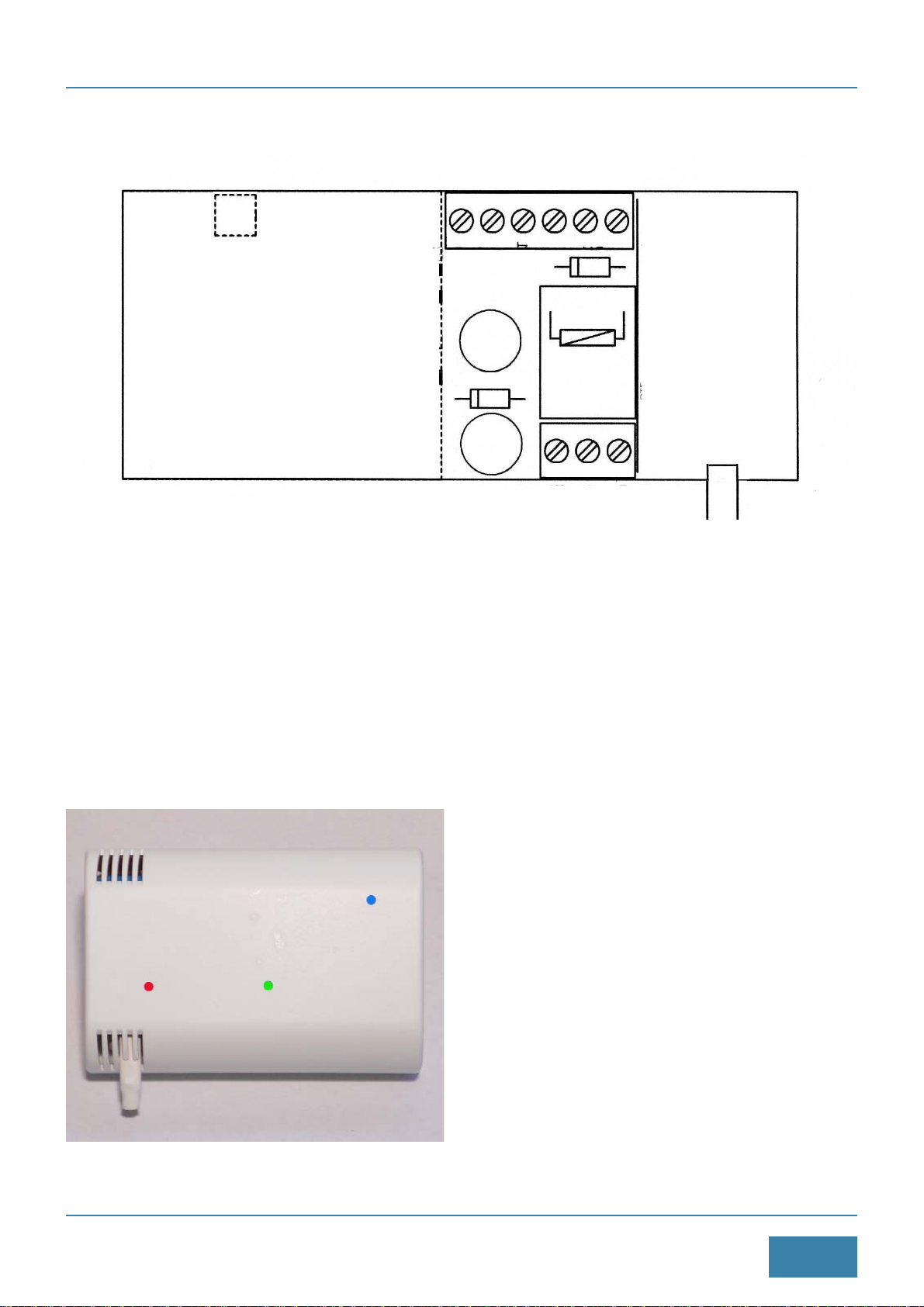
2.3 Panel Description
Blue LED Indicates the status of the GSM
GSM - Illuminated fixed, signal excellent
- 2 flashes, average signal
- 1 flash, low signal
(connect external antenna or
move the device)
- Off, GSM is not connected
Green LED Indicates the operating status:
RUN - 1 flash, comfort OFF
- 2 flashes, comfort ON
- Fixed search Network
Red LED Indicates the status of the relay:
BOILER - Illuminated, relay activated,
- Off, off relay.
Note. The green LED inside is not significant, is used
in the programming phase.
SMA
CONNECTOR
TEMPERATURE
SENSOR
+V -V * * * *
NO C NC

Copyright©2015 EVR Electronics.
All right reserved. Print only for private use.
www.gsmcontrol.biz
8
3.1 Command C (Comfort Function) - Activation / deactivation temperature Comfort
The request to bring and keep the room temperature to the value of the Comfort temperature can be performed
remotely by calling a telephone enabled the number of SIM in CX36 or by sending an SMS with the command C.
This function allows you to heat the home without the user is present. When, at a later time, the user will reach the
home this will already be at the optimum temperature.
Example: 0000CON or 0000COFF
Text SMS Description
0000 Password of the device
C ID command
ON Turns Comfort temperature, the device will manage the boiler so that
the environment is achieved and maintained the temperature Comfort
OFF Off Comfort temperature, the device will have no effect on the boiler
It will be managed by the existing thermostat or boiler thermostat.
If the command is received correctly, the device responds with an SMS containing the status of the Comfort and the
current room temperature:
Comfort: ON - Tint: 7.5 dgC
or
Comfort: OFF - Tint: 20.5 dgC
Alternatively, you can tell the device to confirm the execution of the command with a reply SMS but through a sim-
ple ring. Activating the "answer with ringing" the CX36 after receiving a valid command C and running it, make a
voice call, to the phone that sent the message, lasting some ring to which of course the user does not respond. In
this way, the user gets at no cost (one ring) information of the execution of the command. The function response with
ringing is disabled by default. To enable or disable this feature to send an SMS with the command W followed by the
number 1 or 0.
Example: 0000W1
Text SMS Description
0000 Password of the device
WID command
1 1 = active ringback; 0= off ringback
If the command is received correctly, the device replies with the following SMS:
Setup answer with ringing ON
If the function is disabled, the device will respond with the following SMS:
Setup answer with ringing OFF
Notes:
- The state of Comfort is maintained even in the absence of power. When the power supply status of Comfort (ON
or OFF) is restored to the condition it was in before the power failure.
- Both with ON and OFF Comfort, the CX36 will manage in any case the temperature alarm by sending SMS and
calls if the temperature drops below the alarm threshold set, but did not operate the boiler.
Warning: therefore essential to install in any case a frost protection thermostat in the home or in the boiler.
3. SMS of Use

9
Copyright©2015 EVR Electronics.
All right reserved. Print only for private use. www.gsmcontrol.biz
4. Programming SMS
3.2 R command (Read) - Temperature reading
It is possible at any time to read remotely the internal temperature measured by the device CX36, the Comfort tem-
perature set and the operating condition.
Example: 0000R
Text SMS Description
0000 Password of the device
R ID command
If the command is received correctly, the device replies with the following SMS:
Example: Tint: +18.0 dgC - Tcomf: +20 dgC - Comfort: ON
Where:
Tint = internal temperature measured in degrees Celsius
Tcomf = set comfort temperature in degrees Celsius
Comfort = ON if comfort active; OFF if comfort disabled
4.1 T command (Set Temperature) - Temperature setting Comfort
By default the Comfort temperature is set to + 20 °C. To change this parameter to send an SMS with the command
T followed by the new value. The set temperature is written in a non-volatile memory and is retained even after a
shutdown and a restart of the device.
Example: 0000T22
Text SMS Description
0000 Password of the device
TID command
22 Comfort temperature in Centigrade (number 10 to 40)
If the command is received correctly, the device replies with the following SMS:
Setup Temperature OK Comfort T = 22 dgC
Note:
- To know the comfort temperature set to send the command T ?: 0000T?

Copyright©2015 EVR Electronics.
All right reserved. Print only for private use.
www.gsmcontrol.biz
10
4.2 Command U (Users) - Programming telephone numbers Users
You can program the device up to 5 phone numbers of mobile users; you must program at least the number of cell
phones User 1. They will have a dual function:
Activate / Deactivate Temperature Comfort
The programmed numbers will be able to activate / deactivate the maintenance of room temperature to the set tem-
perature as Comfort. The CX36 reads the caller ID (without going to the line) and if present in memory "switch" func-
tion comfort (the active if it was off and vice versa).
If activated (Comfort ON), the device makes a call lasting some ring towards the user (who will not respond) to com-
municate the execution of the command. All this at no cost by both the mobile user that the SIM card in CX36.
When disabled (Comfort OFF) the device does not send ringback user. It is assumed that this step is performed
locally to exclude the thermostat GSM and pass control to the original thermostat or before leaving the house.
Feedback is entrusted to the green LED RUN.
Receiving SMS
Users will receive SMS messages stored sent voluntarily by the CX36. In particular, the User will receive 1 SMS
credit and residual maturity SIM if the Echo function is enabled; Users 1 through 5 will receive an SMS alert if the
temperature drops below the alarm threshold.
Example: 0000U1+393939002525*
Text SMS Description
0000 Password of the device
UID command
1of the ID number to be programmed (number from 1 to 5)
+393939002525 Mobile number to program full of international identification
* Symbol End of message
If the program is successful, the device replies with the following SMS:
Setup command OK User 1 programmed: +393939002525
Otherwise, the device will respond with the following text message:
Programming User Failed
Notes:
- You can program from 1 to 5 mobile numbers.
- You must program at least one cell phone number user.
- To delete, for example, the mobile phone number in the third position, send the following SMS: 0000U3 *
- To know the numbers stored as Members send the command U?: 0000U?
- The maximum length of each number is 16 digits.
- Always insert the country code before the number, +39 for Italy.
- Carefully read the SMS response verifying that it is the memory location that the mobile phone number are correct.

11
Copyright©2015 EVR Electronics.
All right reserved. Print only for private use. www.gsmcontrol.biz
5. Utility SMS
5.1 Command TA (Alarm Temperature) - Temperature setting alarm
The CX36 spontaneously generates alarm SMS and voice calls to mobile users stored if the temperature falls below
a certain value (Temperature alarm); in this case the CX36 send a single SMS message to each mobile phone num-
ber User. The reactivation of the frost alarm management is done automatically when the ambient temperature
exceeds the threshold temperature alarm over 5 °C. By default, the temperature alarm is set to + 7 °C. To change
this parameter to send an SMS with the command TA followed by the new value. The set temperature is written in
a nonvolatile memory and remains stored even following a power off and a power on of the device.
Example: 0000TA4
Text SMS Description
0000 Password of the device
TA ID of the command
4Alarm Temperature in degrees Centigrade (number from 1 to 9)
If the command is received correctly, the device replies with the following SMS:
Temperature Alarm Setup OK T = 4 dgC
Notes:
- To know the temperature set to send the command T?: 0000T?
- To disable the sending of SMS alarm Frost set the temperature alarm to zero: 0000TA0
To draw attention to these messages, you can tell the CX36 to make, after sending the SMS, also a voice call last-
ing some ring (to which of course the recipient will not respond) to highlight the user ' arrival of the message. The
ringing function is enabled by default.
Example: 0000L1
Text SMS Description
0000 Password of the device
LThe ID of the command
11 = enable ringing Alert; 0 = disables ringing Alert
If the command is received correctly, the device replies with the following SMS:
Setup Ring Alert ON
If the function is disabled, the device will respond with the following SMS:
Setup Ring Alert OFF

Copyright©2015 EVR Electronics.
All right reserved. Print only for private use.
www.gsmcontrol.biz
12
5.4 Command P (Password) - Programming password
Use this command to program a new password for the device. Each SMS programming and command must begin
with the password.
Example: 0000P12341234
Text SMS Description
0000 Current password device
PID command
1234 New device password (4 numbers)
1234 Repeat new password
If the program is successful, the device replies with the following SMS:
Setup command OK Password Updated
Otherwise, the device will respond with the following text message:
Programming Password Failed
notes:
- The device's default password is 0000 (four zeros).
- The password must contain only numbers and must have a fixed length of 4 numbers.
- Note carefully the new device password.
5.3 Command F (Firmware) - Read firmware version
This command allows you to read the firmware version.
0000F
Text SMS Description
0000 Password of the device
F ID command
If the command is received correctly, the CX36 replies with the following SMS:
GSM-CX36S R2, 357541000172165
Text SMS Description
GSM-CX36S R2 code of the device and software version
357541000172165 IMEI Code of GSM
5.2 EC command (Echo) - Enable / Disable Echo SMS
All text messages sent to the CX36 are considered valid and executed only if they start with the correct 4-digit pass-
word. The device return the invalid received SMS to the phone user number 1 (User1). This is convenient for receiv-
ing SMS messages sent by the operator relating to the lapse of the SIM and the related tax credit. The Echo func-
tion can be enabled or disabled by the following command:
0000EC1
Text SMS Description
0000 Password of the device
EC ID command
11 = enable function Echo (default); 0 = disable function Echo
For example: if we send the CX36 an SMS with the text ABCDE, User1 will receive the following SMS: SMS ECHO:
ABCDE. If the Echo function is disabled, by sending an SMS with invalid password, the CX36 does not send SMS
but the green LED flashes 3 times outside.

13
Copyright©2015 EVR Electronics.
All right reserved. Print only for private use. www.gsmcontrol.biz
5.5 External antenna and Command N (Network) - Check Network
The CX36 has an internal antenna. If the place of installation the GSM signal (measured by any mobile phone) is of
at least 3 or 4 notches the internal antenna is typically sufficient to ensure proper operation of the device.
Conversely, if the signal is less need to connect the rod antenna with cable. The antenna is hermetic and can there-
fore also be placed outside, for instance in homes stone mountain where the GSM signal is present only outside of
the dwelling.
After installation check the quality of GSM signal via the command N. The goodness of the GSM radio signal is
expressed as a number from 0 to 31, 0 corresponds to -115 dBm (ultra-low signal) and 31 is equivalent to -52 dBm
(maximum signal).
0000N
Text SMS Description
0000 Password of the device
NID of the command
If the command is received correctly, the CX36 replies with the following SMS: GSM signal: 20
Gently pull up the tab on which is the GSM modem and
the SIM holder to remove it from the base.
Under this tab is mounted a connector type SMA-F.
Screw in the latter SMA-M of the rod antenna.
With a wire cutter to cut laterally the container so as to
allow the output of the antenna cable.
Insert the card to the base by pressing it towards the
main base board.

Copyright©2015 EVR Electronics.
All right reserved. Print only for private use.
www.gsmcontrol.biz
14
6. Commands list
COMMAND DESCRIPTION EXAMPLE
RRead status 0000R Go back an SMS with the ambient temperature, the
temperature Comfort and the state of Comfort
CON Activate Comfort 0000CON Taking the device in Comfort ON
COFF Disable Comfort 0000COFF Taking the device in Comfort OFF
WResponse to the command C 0000W0 Reply with SMS
TSet temperature Comfort 0000T22 Comfort temperature set at 22 °C
TA Set temperature alarm 0000T4 Set alarm at 4 °C
NRead GSM signal 0000N Go back an SMS with number from 1 to 30
EC Echo SMS 0000EC1 Enables the Echo SMS
FRead firmware version 0000F Back an SMS with firmware version number
PProgram Password 0000P12341234 Program 1234 as a new password
UUsers program 0000U1+393939002523* Program the cell. +393939002525
with User 1
15
Copyright©2015 EVR Electronics.
All right reserved. Print only for private use. www.gsmcontrol.biz
7. Safety Instructions
- This device must be connected in parallel with the original thermostat. Do not remove or disconnect the thermostat
original.
- Before you approach the device or opening the container to remove the adapter from the mains or make sure the
device is not powered.
- During installation, the device must not be connected to the supply voltage.
- Do not wet the product.
- Using tools on components, modules or devices, make sure they are disconnected from the power supply and that
components that may have stored an electric charge is discharged.
- All cables connected to the device, the module or components have to be checked regularly for signs of damage
or wear. If the cables are visibly damaged must immediately stop the operation of the device and provide for the
replacement of damaged cable.
- When using components or modules comply with the technical specifications outlined in their descriptions.
- If the electrical characteristics for the end user are not clear or complete consult a specialist installer.
- Before putting the device into operation must ensure that it is suitable for the application to be played; if in doubt
seek advice to an expert or the device vendor.
- The supplier can not be held responsible for any errors in usage or connection; therefore it can not be held liable
for consequential damages.
- Devices which operate with a voltage greater than 35 volts must be connected by a professional electrician. Do not
exceed the limits specified in the technical specifications.
- Before putting the device into operation check that there are no current leakage on the container.
-All cables added to the product to connect to other devices must be fitted with ferrites to limit electromagnetic emis-
sions.
- The power inputs and so must be protected with fuses sized correctly.
- Information for users pursuant to art. 13 of Legislative Decree 25 July 2005, n. 151 "Implementation of
Directive 2002/95 / EC, 2002/96 / EC and 2003/108 / EC on the restriction of use of hazardous substances
in electrical and electronic equipment and the disposal of waste."
The crossed bin symbol on the appliance or on the packaging indicates that the product at the end of its
life must be collected separately from other waste.Appropriate separate collection for the subsequent for-
warding of the decommissioned product to recycling, treatment and environmentally compatible disposal
helps prevent negative impact on the environment and health and promotes the reuse and / or recycling of materi-
als making up the equipment. Illegal dumping of the product by the owner involves the application of administrative
sanctions provided by law.

Copyright©2015 EVR Electronics.
All right reserved. Print only for private use.
www.gsmcontrol.biz
16
Modello: GSM-CX36
File: GSM-CX36-R6-Instruction
Data: 20 Ottobre 2015
The manufacturer reserves the right to change product specifications or to cease production of the products
without prior notice and have to incorporate or provide new functions or the new instructions in the products
already sold. The manufacturer can not be held responsible for any loss or damage, direct or indirect, that may
result from use of the products. It noted that remote management is a free choice and the user himself is fully
and solely responsible. We accept no liability resulting from failure of the equipment for possible causes of fail-
ure, malfunction, improper installation, or by external causes such as power failure or GSM signal. The products
are not suitable for use as parts of life support systems, or systems that might create hazardous situations of
any kind.
8. Technical features
GSM section
- Modem Quad-Band GSM / GPRS
850/900/1800/1900 MHz
- Output Power Class 4 (2W) @ 850/900 MHz
- Output Power Class 1 (1W) @ 1800/1900 MHz
General
- 1 relay for control boiler
with contact rating 6A 250V
- 1 internal sensor for temperature measurement
- Password protection of each command
- Response to commands with SMS or ring
- 5 programmable Users
- Sending SMS alarm frost
- Echo function SMS
- Operating Temperature: 0 ° C to + 55 ° C
- Power supply: 12 Vdc
- Power input: 150 mA
- Impulsive consumption: 1 A
- Container with a base for wall mounting
- Dimensions: 80 x 120 x 33 mm h
Specifications subject to change without notice.
This product is guaranteed against defects in components and assembly for a period of one year from the date of
the sale. The warranty is valid only if the user has a copy of the original proof of purchase that invoice or receipt.
The manufacturer's liability is limited to the repair of the defect or, if necessary, to replace or repair or refund the
defective component. The costs and risks associated with the transport, removal or repositioning of the product, and
any other costs directly or indirectly connected to the repair, can not be attributed to the manufacturer. The manu-
facturer can not be held responsible for any damage caused by a malfunction of the product.
9. Warranty
9.1 Technical support
For technical support on the product you can contact us at the following address:
Table of contents


