Bpt TH 350 User manual

THERMOPROGRAM
DIGITAL PROGRAMMABLE
THERMOSTAT
TH 350
INSTRUCTIONS FOR USE
TH350E 24806610 13-03-13

2
Congratulations on the purchase of this TH350 thermostat.
For best performance and to enable the best use of this
programmable thermostat's characteristics and functions
please read this manual carefully and keep it available for
future reference.
WARNINGS FOR THE INSTALLER
• Read the warnings contained herein with care as they
furnish important instructions regarding safe use, instal-
lation and maintenance.
• After removing the packaging check the condition of
the unit.
• The system must be installed in compliance with current
safety standards.
• The manufacturer declines all liability for any damage as
a result of improper, incorrect or unreasonable use.
• Should the unit be in need of repair contact only a tech-
nical support centre authorised by the manufacturer.
• Failure to comply with the above instructions may com-
promise the unit's safety.
THERMOPROGRAM TH350
The TH350 programmable thermostat has been designed
to ensure perfect temperatures any time of day, any day
of the week.
The TH350 features a new temperature control system
and new functions.
The TH350 has been designed to guarantee ideal tem-
perature conditions and to adapt itself to all types of sys-
tems having differing thermal inertias (convector heaters,
radiant underfloor heating, electric heaters, etc.).
It is possible to choose between differential control mode
and integral proportional control mode (management of
cycles/hour). The latter allows the programmable ther-
mostat to reduce the time the boiler is in operation as the
room temperature approaches the desired temperature.
This provides a greater reduction in consumption while
at the same time providing the highest levels of comfort.
The TH350 has new features and functions that include:
• a backlit display;
• the possibility to set boiler ignition down to the quar-
ter-hour;
• a new AUTOMATIC ADVANCE function that allows the
TH350 to self-learn the periodicity required to achieve the
desired temperature at any chosen point in time;
• an option to calibrate the measured room temperature;
Use only ALKALINE batteries

• the use of a GSM relay interface which makes it possible
to remotely activate a manual or timer controlled pro-
gramme thus ensuring a welcoming return home.
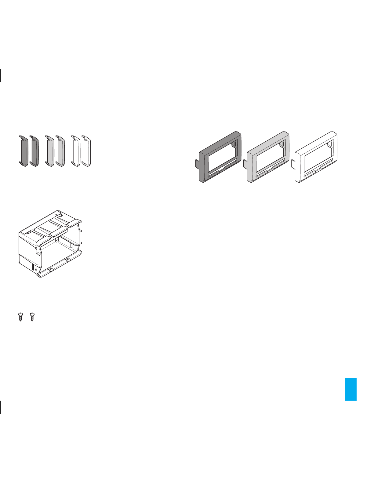
Wall mounting the installation takes only minutes. The
thermostat can be connected to the heating/cooling
installation simply by means of two wires.
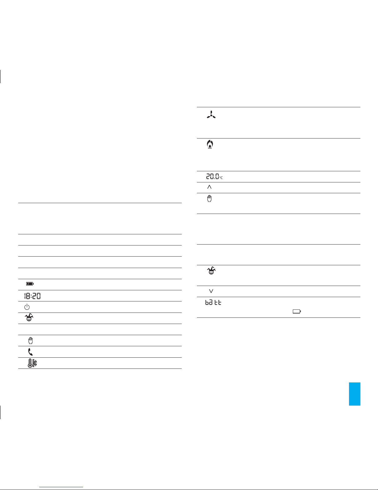
Three alkaline LR03 1.5V penlight AAA batteries are
used to power TH350 for over a year. Once installed
the unit is ready for operation based on its permanent
memory standard programme. Based on actual needs,
the programme can be modified as required by setting
the desired temperatures for different times of the day
and week.
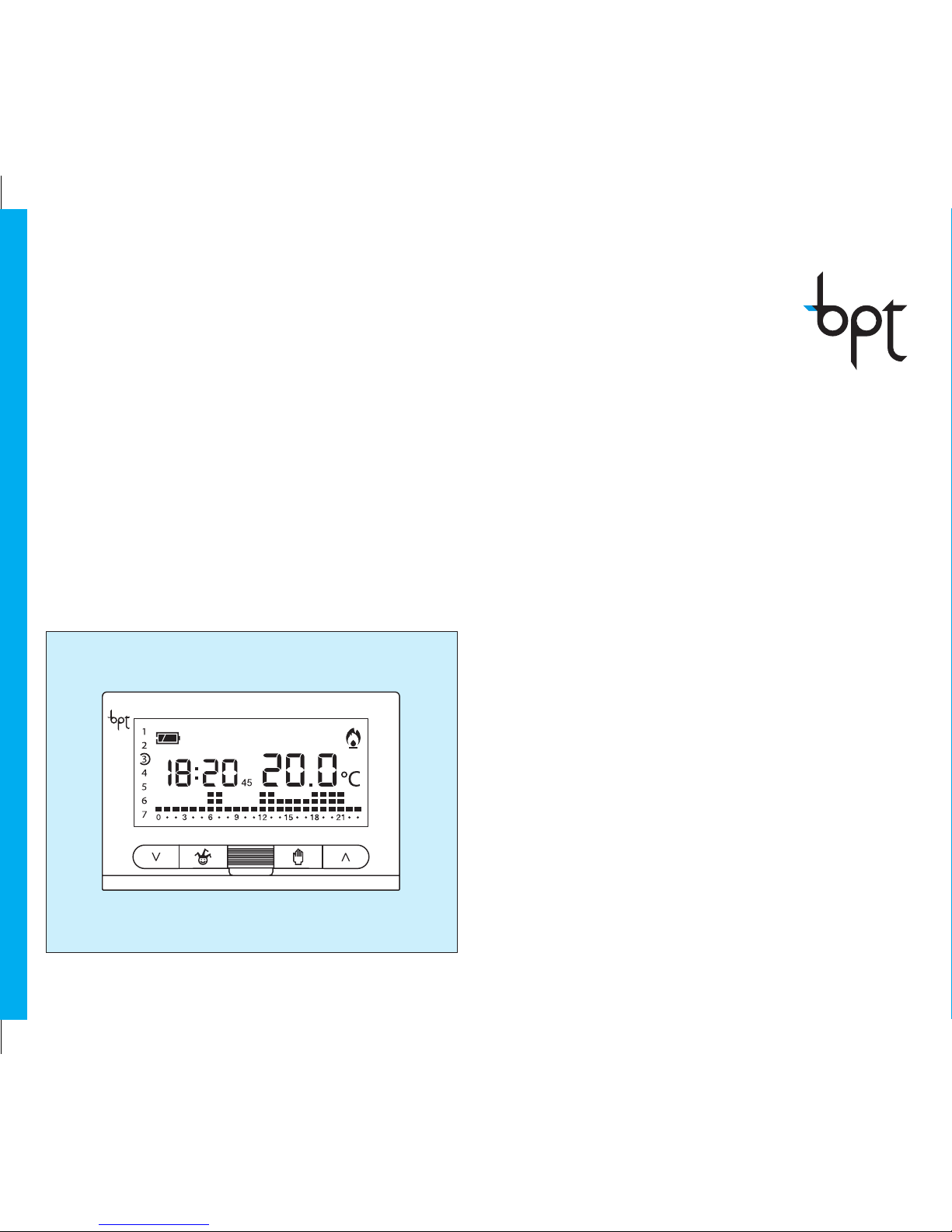
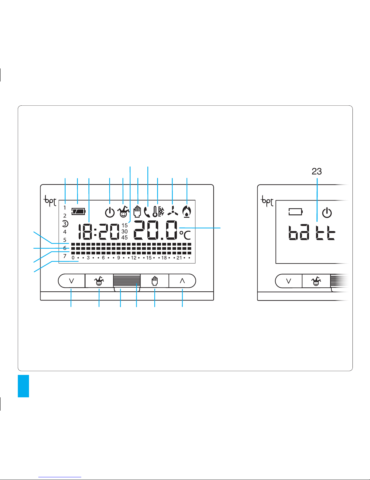
The TH350 can be programmed with great ease, even
before it is installed. The spacious backlit display makes
this easier, because at any time it permits the viewing
of all data and programmes which can subsequently be
changed as required.
Pressing the programming buttons causes the display to
light up for about 15 seconds from the last time any key
was pressed.
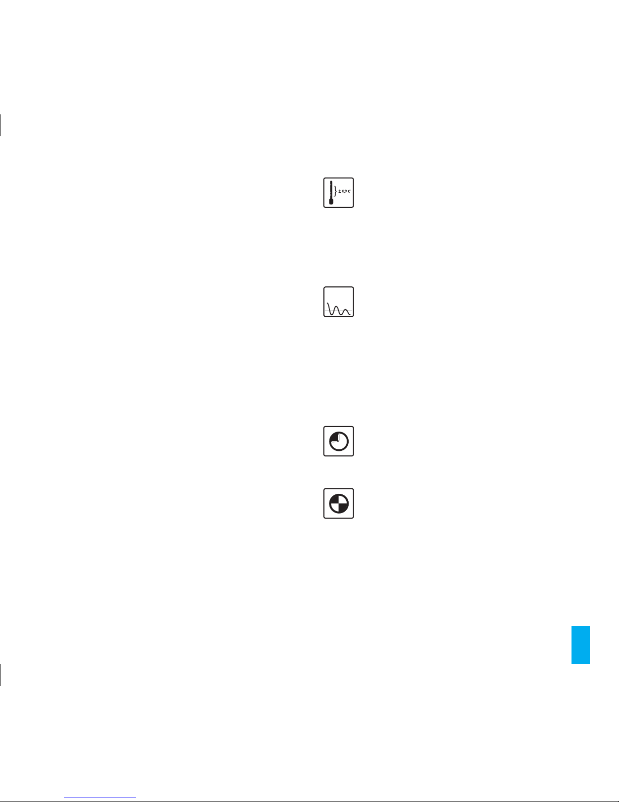
The thermal differential is programmable from 0°C to
0.9°C. The TH350 can control both heating and air-condi-
tioning systems, and can be installed as a replacement for
a previous on/off programmable thermostat.
Thermal differential is programmable from
0°C to 0.9°C.
Suitable for systems with differing thermal inertias
(convector heaters, underfloor heating, electric
heaters) ensuring best system use with the lowest
possible consumption.
Proportional/integral adjustment programme
Allows for energy consumption optimisation with
maximum room comfort thus reducing boiler
operating times based on the difference between
the set temperature and the room temperature.
The smaller the difference between these tem-
peratures the shorter the boiler ignition time will
be compared to previously.
AUTOMATIC ADVANCE function
TheTH350 self-adjusts so as to provide the desired
temperature at the pre-selected time.
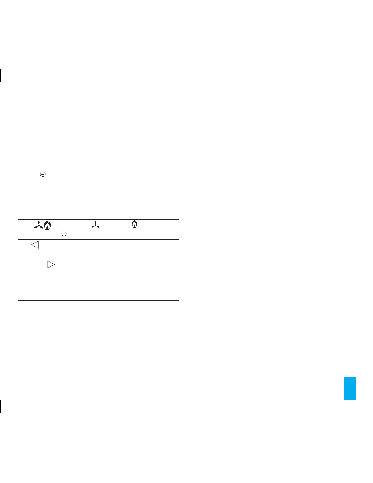
Boiler ignition and shutdown setting with 15
minute precision
In automatic operating mode the TH350 can
ignite or shut-down the boiler on the half or
quarter of each hour, thus allowing for more pre-
cise management of room comfort programmes
and substantially optimising boiler energy con-
sumption.
3
+3°C
–3°C
PI
+3°C
–3°C
PI
+3°C
–3°C
PI
+3°C
–3°C
PI

4
The TH350 programmable thermostat is made up of:
main unit
Supports
Calibration of temperature measurement
If the TH350is not properly installed (e.g. installed
near a heat source), temperature measurement
may be incorrect or may not correspond to the
actual temperature.
To solve this problem, it is possible to calibrate the
reading to within ±3°C and in so doing optimise
comfort and consumption.
Easy and complete daily/weekly 3-level pro-
gramming
With the TH350, temperatures for any time of any
day of the week can be programmed in a simple
and intuitive manner. Just a few buttons are used
to set the hourly temperature while at the same
time providing constant on-screen monitoring of
programming progress.
Common domestic installation switch sur-
round compatibility
ABB: Series ELOS;
AVE: SISTEMA 45, Series 44, Series BANQUISE;
BTICINO: Series LIVING INTERNATIONAL, LIGHT,
LIGHT TECH, AXOLUTE, LUNA, LIVINGLIGHT (air,
quadre tonde);
GEWISS: Serie PLAYBUS, SYSTEM, CHORUS;
LEGRAND: Series VELA, CROSS;
VIMAR: Series PLANA, IDEA, EIKON, ARKÉ;
+3°C
–3°C
PI
+3°C
–3°C
PI
+3°C
–3°C
PI
A
C
B
D

5
Adapter blanking fittings
(2 white, 2 anthracite grey and 2 aluminium grey)
Back-box
Fixing screws
Front cover
(1 white, 1 anthracite grey and 2 aluminium grey)

6
4
2
1
3
6
58 9 11
12
13 14 15
10
16
7
18
1920
22 21 17
1
23

7
SYMBOLS AND EXTERNAL CONTROLS (see fig. 1)
ATTENTION. To turn on the backlight simply press any
key. To enter one of the selected functions (e.g. setting the
clock, etc.) the appropriate button will need to pressed
twice.
The backlight stays on for 15 seconds after the last press
of a button.
INFORMATION DISPLAYED
1
0 ÷ 23
Program display for the hours..
The flashing cursor indicates the hour corre-
sponding to the clock time.
2 Temperature range T1.
3 Temperature range T2.
4 Temperature range T3.
5 1÷7 Select the day.
6 Battery charge status.
7Digital clock.
8 System bypass.
9 All-purpose programme activation.
10 Start-up and shut-down delay periods.
11 Manual operating mode.
12 Remote activation.
13 Protection against frost.
15 COOLING programme.
When the cooling system is in operation this icon is
animated.
15 HEATING programme.
When the heating system is in operation this icon is
animated.
16 Digital clock.
17 Button to increase temperature, time, etc.
18 Button to select MANUAL or AUTOMATIC oper-
ating mode.
19 Temperature sensor.
ATTENTION. Avoid touching the sensor so as not
to distort the temperature reading.
20 Tab for extracting the main unit of the thermo-
stat from the back-box.
21 ALL-PURPOSE or MANUAL TIMER-CONTROLLED
programme activation button.
22 Button to decrease temperature, time, etc.
23 When this warning appears, it means that the
batteries are exhausted .

8
1
L
1
2
L
24 25 26 27 28 29 30 31
2

9
INTERNAL CONTROLS
To access the internal control buttons extract the tab L
and pull the main unit of the thermostat forwards until it
is blocked as indicated in fig 2.
24 RReset.
25 Setting the clock and the start-up and
shut-down delay period.
26 PTemperature programming in the three
ranges T1, T2, T3.
Setting of operating parameters.
27 COOLING ( ) HEATING ( ) or OFF MODE
programme selection.
28 0÷23 Decrease of the hour within the ‘Daily’
programme display.
29 0÷23 Increase of the hour within the ‘Daily’
programme display.
30 1÷7 Select the day.
31 CCopy programme.

10
19 - Overall number of system operating hours . . . . . 39
20 - Remote control . . . . . . . . . . . . . . . . . . . . . . . . . . . . . . . . 39
21 - Reset .......................................... 42
22 - Battery replacement ........................... 44
23 - Technical characteristics. . . . . . . . . . . . . . . . . . . . . . . . 45
CONTENTS
Chapter.........................................Page
1 - Installation . . . . . . . . . . . . . . . . . . . . . . . . . . . . . . . . . . . . . 11
2 - Electrical connections .......................... 17
3 - Setting the clock . . . . . . . . . . . . . . . . . . . . . . . . . . . . . . . 20
4 - Heating, cooling and system OFF programming 22
5 - Pre-memorised programmes. . . . . . . . . . . . . . . . . . . 22
6 - Daily programme temperature personalisation 23
7 - Temperature level personalisation for the
heating program. . . . . . . . . . . . . . . . . . . . . . . . . . . . . . . 25
8 - Temperature level personalisation for the
cooling program . . . . . . . . . . . . . . . . . . . . . . . . . . . . . . . 27
9 - ALL-PURPOSE programme ..................... 27
10 - Manual operation .............................. 28
11 - System bypass ................................. 29
12 - Frost protection function. . . . . . . . . . . . . . . . . . . . . . . 30
13 - Manual timed program ........................ 31
14 - System ignition and shut-down delay timing
adjustment .................................... 32
15 - Temperature measurement calibration . . . . . . . . . 34
16 - Automatic advance ............................ 34
17 - Thermal differential ............................ 35
18 - Proportional-Integral programming ............ 36

11
1 INSTALLATION
Install the unit in a position which is suitable for correct
room temperature measurement for example on an
internal wall. Avoid installation in niches, behind doors or
curtains, or near heat sources.
The TH350 is designed to be installed within a 3 module
recessed back-box having a depth of 50mm. Proceed as
follows:
• Pull the tab
L
forwards. The main unit of the thermostat
will follow until it is blocked by two lateral stop tabs (3).
Press the lateral tabs marked by the symbol (fig. 4)
and extract the main unit of the thermostat completely.
• Insert 3 alkaline LR03 penlight AAA 1.5V batteries
within the housing. Make sure the poles face the right
way as shown on the bottom of the housing (fig. 5).
L
1
3
L
1
45
Use only ALKALINE batteries

12
ATTENTION. Inserting the batteries the wrong way round
could damage the unit. Once these steps have been
carried out correctly the symbols shown in figure 6 will
appear on the display.
Choose the support (A, B, C or D) and front facing cover
as a function of the surround to be fitted.
To remove the front cover proceed as indicated in figure 7.
76

13
8
10
9
11
BTICINO
(
Light Series, Light
Tech Series, Living
International Series)
VIMAR
(
Plana Series, Eikon
Series)
LEGRAND
Vela Series (Vela
Quadra, Vela Tonda),
Cross Series
Support A Support A
Support BSupport B
GEWISS
Playbus Series
(Playbus, Playbus
Young)
AVE
(
Banquise Series,
SISTEMA 45)
VIMAR
Idea Series (Idea, Idea Rondò)

14
ABB
(
Elos Series)
GEWISS
(
SYSTEM Series)
BTICINO
(
Axolute Series,
Luna Series)
BTICINO
(
Livinglight Quadre)
VIMAR
(
ARCHÉ Series)
BTICINO
(
Livinglight Tonde)
GEWISS
(
CHORUS Series)
12 13
14 15
Support B
Support C
Support B
Support C

15
AVE
(
44 Series)
BTICINO
(
Livinglight AIR)
Support D
2
1
17
16
The trade names Playbus, Playbus Young, System e
Chorus are the property of GEWISS S.p.A
The trade names Light, Light Tech Livinglight, Axolute,
Luna e Living International are the property of BTICINO
S.p.A;
The trade names Plana, Idea, Eikon, Idea Rondò e Arké are
the property of VIMAR S.p.A;
The trade names Vela, Cross are the property of
LEGRAND S.p.A
The trade names Banquise SISTEMA 45 e serie 44 are the
property of AVE S.p.A
Il marchio Elos is the property of ABB S.p.A
Should the necessity arise to change the support then
proceed as indicated in fig. 17.

16
18
3 module
recessed
back-box
Back-box Support
L
Adaptors Main unit Support

17
19
• Electrical connections are to made within the back-box
terminal block as indicated in either diagram 20 or 21.
• Paying attention to the UP direction indication use the
screws supplied to mount the unit to the back-box (fig.
19).
• Push the main unit of the thermostat all the way to the
back and then fit the surround.
Insert the locking tab L.
2 ELECTRICAL CONNECTIONS
The wiring will depend on the type of equipment to be
controlled by the thermostat: refer to the diagram in fig.
20 or 21.
KEY
Mains power supply wires
N= neutral
L= live
Relay contacts
C= common
NA = normally open contact
NC = normally closed contact
NCNA C
1
2
U1
L
N
TH350
20
LOAD

18
NCNA C
1
2
L
N
TH350
U2
M
LOAD
OPEN
CLOSED
21
Remote control inputs
1input
2input
Loads
U1 = boiler, circulation pump, solenoid valve, etc.
U2 = motorised valve
NOTE. For connection details, refer to the technical docu-
mentation of the device to be controlled.

19

20
22
23
24
25
3 SETTING THE CLOCK
3.1-
Remove the main unit of the unit.
3.2- Press the button twice (fig. 22).
The first press of the button simply activates the back-
light.
The minutes digits flash.
3.3- Press button or until the correct value for the
minutes is reached (fig. 23).
3.4- Press button (fig. 24).
The hour digits flash.
3.5- Press either button or until the correct value for
the hour is reached (fig. 25).
3.6- Press button (fig. 26).
The indicator for the days of the week flashes.
3.7- Press button or until the correct value for the
minutes is reached (fig. 27).
3.8- Press button to end the procedure for setting the
time and day (fig. 28).
The colon between the hours and minutes flashes to confirm
Other manuals for TH 350
1
Table of contents
Other Bpt Thermostat manuals