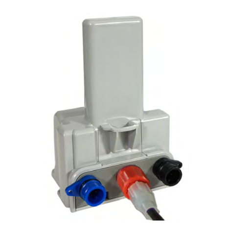
EVSE 3727 Series User manual

Control Module Inc., EVSE LLC
EVSE Gateway Module
Model 3727 Family
User Manual and Installation Guide
Model 3727 Family
EVSE Gateway Module
Patents Pending
3727-UG-200
November 2017

State of the Art EVSE
User Manual
Model 3727-A02XX EVSE Gateway
Copyright EVSE LLC 2017. All rights reserved. Patents pending.
Page 1
Contents
Important Notes .............................................................................................................................................................................3
Safety and Compliance ...............................................................................................................................................................3
Warranty Information and Disclaimer........................................................................................................................................3
Limitation of Liability ..................................................................................................................................................................3
FCC Compliance Statement ........................................................................................................................................................3
Exposure to Radio Frequency Energy .........................................................................................................................................3
Copyright and Trademarks .........................................................................................................................................................4
Instructions Pertaining To Risk of Fire or Electrical Shock..............................................................................................................5
Instructions De Sécurité Importantes.............................................................................................................................................6
Introduction to Model 3727-200 Gateway Module .......................................................................................................................7
Specifications..............................................................................................................................................................................8
Lockout/Tagout........................................................................................................................................................................ 10
Installation ................................................................................................................................................................................... 11
Wiring ...................................................................................................................................................................................... 12
Indicator Lights –Cell Modem Status ...................................................................................................................................... 13
Indicator Lights - Server LEDs .................................................................................................................................................. 14
Accessing the Web Browser Interface......................................................................................................................................... 15
Ethernet Connection..................................................................................................................................................................... 15
Cellular Connection ......................................................................................................................................................................15
Logging In......................................................................................................................................................................................15
Changing the IP Address for an Ethernet Connection ..................................................................................................................16
Setting Up a ZigBee Mesh Network............................................................................................................................................. 17
Testing the ZigBee Mesh Network........................................................................................................................................... 18
Replacing a ZigBee Mesh Gateway Module ............................................................................................................................ 19
Web Browser Interface Operation .............................................................................................................................................. 20
Changing EVSE Assigned Numbers (Serial Connection)........................................................................................................... 20
Viewing EVSE Status and Messages......................................................................................................................................... 21
Status Reporting ...................................................................................................................................................................... 22
Current Status...............................................................................................................................................................................22
Historical Events ...........................................................................................................................................................................22
Charge History ..............................................................................................................................................................................22
App Versions.................................................................................................................................................................................23
Connecting to a Network Management System...................................................................................................................... 23
System Configuration .............................................................................................................................................................. 25

State of the Art EVSE
User Manual
Model 3727-A02XX EVSE Gateway
Copyright EVSE LLC 2017. All rights reserved. Patents pending.
Page 2
Moving, Transporting and Storage .......................................................................................................................................... 26
Customer Support:....................................................................................................................................................................... 27
Warranty...................................................................................................................................................................................... 28

State of the Art EVSE
User Manual
Model 3727-A02XX EVSE Gateway
Copyright EVSE LLC 2017. All rights reserved. Patents pending.
Page 3
Important Notes
Safety and Compliance
This document provides instructions for installing and using the Watt Point™ Gateway Module 3727-200, which manages
data communication within a network of Watt Point Charging Stations (EVSE’s). Before installation of the Watt Point
Gateway Module by licensed professionals, you should review this manual carefully and consult with a licensed
contractor, licensed electrician and trained installation expert to ensure compliance with local building practices, climate
conditions, safety standards, and state and local codes. As part of a total EVSE network, the Watt Point Gateway Module
and Charging Station should be inspected by a qualified installer prior to the initial use. Under no circumstances will
compliance with the information in this manual relieve the user of responsibility to comply with all applicable codes or
safety standards. This document describes the most commonly-used installation and mounting scenarios. If situations
arise in which it is not possible to perform an installation following the procedures provided in this document, contact
Control Module Inc., EVSE LLC. Control Module Inc., EVSE LLC, is not responsible for any damages that may occur
resulting from custom installations that are not described in this document.
Warranty Information and Disclaimer
Your use of, or modification to, the Watt Point Gateway Module in a manner in which the Watt Point Gateway Module is
not intended to be used or modified will void the limited warranty. Other than any such limited warranty, the Control
Module Inc., EVSE LLC, products are provided “AS IS,” and Control Module Inc., EVSE LLC, and its distributors
expressly disclaim all implied warranties, including any warranty of design, merchantability, fitness for particular purposes
and non-infringement, to the maximum extent permitted by law.
Limitation of Liability
IN NO EVENT SHALL CONTROL MODULE INC, EVSE LLC, OR ITS AUTHORIZED DISTRIBUTORS BE LIABLE FOR
ANY INDIRECT, INCIDENTAL, SPECIAL, PUNITIVE, OR CONSEQUENTIAL DAMAGES, INCLUDING WITHOUT
LIMITATION, LOST PROFITS, LOST DATA, LOSS OF USE, COST OF COVER, OR LOSS OR DAMAGE TO THE
WATT POINT CHARGING STATION OR GATEWAY MODULE, ARISING OUT OF OR RELATING TO THE USE OR
INABILITY TO USE THIS MANUAL, EVEN IF CONTROL MODULE INC, EVSE LLC, OR ITS AUTHORIZED
DISTRIBUTORS HAVE BEEN ADVISED OF THE POSSIBILITY OF SUCH DAMAGES.
FCC Compliance Statement
Note: This equipment has been tested and found to comply with the limits for a Class A digital device, pursuant to part
15 of the FCC Rules. These limits are designed to provide reasonable protection against harmful interference when the
equipment is operated in a commercial environment. This equipment generates, uses and can radiate radio frequency
energy and, if not installed and used in accordance with the instructions, may cause harmful interference to radio
communications. Operation of this equipment in a residential area is likely to cause harmful interference in which case
the user will be required to correct the interference at his own expense.
Important
Changes or modifications to this product not authorized by Control Module Inc., EVSE LLC, could affect the EMC
compliance and revoke your authority to operate this product.
Exposure to Radio Frequency Energy
The radiated power outputs of the ZigBee® radio and cellular modem (optional) in this device are below the FCC radio
frequency exposure limits for uncontrolled equipment. This device should be operated with a minimum distance of at
least 7.9 inches (20 cm) between all antennas and a person’s body and must not be co-located with any other antenna or
transmitter by the manufacturer, subject to the conditions of the FCC Grant.

State of the Art EVSE
User Manual
Model 3727-A02XX EVSE Gateway
Copyright EVSE LLC 2017. All rights reserved. Patents pending.
Page 4
Copyright and Trademarks
Copyright 2015 Control Module Inc., EVSE LLC. All rights reserved. This material is protected by the copyright laws of
the United States and other countries. It may not be modified, reproduced or distributed without the prior, express
written consent of Control Module Inc., EVSE LLC.
Watt Point is a U.S. registered trademark and service mark of Control Module Inc., EVSE LLC. All other products or
services mentioned have the trademarks, service marks, registered trademarks or registered service marks of their
respective owners. Control Module Inc., EVSE LLC, has filed several patent applications.
ZigBee is a registered trademark of the ZigBee Alliance.

State of the Art EVSE
User Manual
Model 3727-A02XX EVSE Gateway
Copyright EVSE LLC 2017. All rights reserved. Patents pending.
Page 5
Instructions Pertaining To Risk of Fire or Electrical Shock
The following is a summary of safety concerns relevant to the installation and use of the Model 3727-200 Gateway
Module. Failure to follow these safety instructions may lead to serious injury, death and/or damage to the equipment.
WARNING: is used to provide a warning of hazardous voltage and possibility of electric shock.
CAUTION: is used to provide awareness of important safety information in these instructions.
IMPORTANT SAFETY INSTRUCTIONS
WARNING: Only qualified personnel should perform the installation. This installation must be performed in
accordance with all local electrical/building codes and ordinances. Follow lockout/tagout
procedures.
Improper connection of the equipment grounding conductor may result in a risk of electric
shock. Reference National Electrical Code, ANSI/NFPA 70 for proper sizing of the ground
conductor.
CAUTION: To reduce the risk of fire when installing the Gateway, connect only to a dedicated
circuit with 15A maximum branch circuit over–current protection in accordance with
the National Electrical Code, ANSI/NFPA 70.
To satisfy FCC RF exposure requirements for mobile transmitting devices, a separation
distance of 20 cm or more should be maintained between the antenna(s) of this device
and persons during device operation. To ensure compliance, operations at closer than
this distance is not recommended. The antenna(s) used for this transmitter must not be
co-located in conjunction with any other antenna or transmitter.
Additional considerations which will contribute to safe operation of this unit include the following:
DO: - Read all instructions before using this product.
- The device should be supervised when used around children.
- In case of a problem, contact your installer or CMI Customer Support.
DON’T: - Use this product if the enclosure is broken, cracked, open or shows any other indication of
damage.
- Attempt to repair or service the unit yourself.
SAVE THESE INSTRUCTIONS

State of the Art EVSE
User Manual
Model 3727-A02XX EVSE Gateway
Copyright EVSE LLC 2017. All rights reserved. Patents pending.
Page 6
Instructions De Sécurité Importantes
AVERTISSEMENT: est utilisé pour fournir un avertissement de tension dangereuse et possibilité de choc
électrique.
ATTENTION: est utilisé pour fournir la prise de conscience de l'information de sécurité importante dans ces
instructions.
INSTRUCTIONS DE SÉCURITÉ IMPORTANTES
AVERTISSEMENT: Seul le personnel qualifié devrait effectuer l'installation. Cette installation doit être
effectuée en conformité avec tous les codes électriques/bâtiment locaux et ordonnances. Suivre
les procédures de verrouillage/verrouillage.
Mauvaise connexion de l'équipement de mise à la terre chef d'orchestre peut entraîner un risque
de choc électrique. Référence National Electrical Code, ANSI/NFPA 70 pour le bon
dimensionnement du conducteur au sol.
ATTENTION: Afin de réduire le risque d'incendie, se connecter uniquement à un circuit dédié avec
protection maximum des branches des over–current circuits 15A bis conformément aux
dispositions du Code électrique National, ANSI/NFPA 70.
Pour satisfaire les exigences d'exposition RF de la FCC pour les appareils mobiles de
transmission, une distance de séparation de 20 cm ou plus devrait être maintenue entre
l'utilisation de ce dispositif et les personnes au cours de l'opération de l'appareil. Afin d'assurer
la conformité des opérations à plus proche que cette distance n'est pas recommandée.
L'utilisation utilisée pour cet émetteur ne doit pas être détachée en conjonction avec tout autre
antenne ou émetteur.
Considérations supplémentaires, ce qui contribueront à la sécurité de fonctionnement de cette unité sont les
suivants :
DO: - Lire toutes les instructions avant d'utiliser ce produit.
- L'appareil doit être supervisé lorsqu'il est utilisé autour des enfants.
- En cas de problème, contactez votre installateur ou soutien à la clientèle CMI.
NE PAS: - N'utilisez pas que ce produit si l'enceinte est cassée, fissuré, ouvrir ou afficher toute autre
indication de dommages.
- N'essayez pas de réparer ou d'un service de l'unité de vous-même.
ENREGISTREZ CES INSTRUCTIONS

State of the Art EVSE
User Manual
Model 3727-A02XX EVSE Gateway
Copyright EVSE LLC 2017. All rights reserved. Patents pending.
Page 7
Introduction to Model 3727-200 Gateway Module
The Model 3727-200 Watt Point Gateway Module operates as the central communication system manager for a
network of Electric Vehicle Supply Equipment (EVSE) charging systems.
Communication to each charging system is facilitated by a ZigBee mesh network, allowing the Gateway to be
located up to 66 feet (90m) indoors/urban or up to 164 feet outdoors RF line-of-sight from the nearest ZigBee
equipped electric vehicle charger.
Externally, the Gateway Module is able to communicate to third-party systems via Ethernet, which is standard with
the unit. An optional cellular modem is also available. The modem is configured to be compatible with either of
the AT&T or Verizon networks, but not both simultaneously.
The Gateway Module is packaged in a NEMA 3R-rated enclosure, so it is compatible with outdoor conditions
while providing a degree of protection against wind-blown dust, rain, sleet and external ice formation. If
mounted to a wall, units are shipped with a standard three-prong, 120 VAC, electrical plug. If mounted to a pole
with EVSE chargers, units get their 24VDC operating voltage from the charger. The associated electrical
receptacle must be mounted in a weatherproof, in use enclosure, as well, for the system to be truly weatherproof
for outdoor installations.

State of the Art EVSE
User Manual
Model 3727-A02XX EVSE Gateway
Copyright EVSE LLC 2017. All rights reserved. Patents pending.
Page 8
Specifications
Product Code
Model 3727-200
Mounting: On EVSE Pole, Remote Pole or Wall
Communication to EVSE: ZigBee Mesh or Serial RS-232
Communication to Network: Ethernet or Cellular
Electrical
Voltage
Power Consumption
+24VDC @ 1 amp
Less than 24 watts (Based on Configuration)
Hardware
CPU
Ethernet
ZigBee
Environmental
1 GHz
IEEE 802.3 10Base-T and 802.3u 100Base-T
Frequencey: 2.4 GHz
Operating Temp
Operating Humidity
NEMA Rating
Compliance
-22F to +122F (-30C to 50C) Ambient
0 to 90% non-condensing
3R
EMC
Accessories
Meets FCC Class A, Canadian ICES-003
Communication to EVSE (ZigBee)
Communication to Network (Cellular
Modem)
Contains - FCC ID: MCQ-PROS2B, IC: 1846A-PROS2B (optional)
Contains - (V) FCC ID: N7N-SL5011, IC: 2417C-SL5011 (optional)
- (A) FCC ID: N7N-SL8090, IC: 2417C-SL8090 (optional)
General
Weight
Size
1.85 pounds
4 in (w) x 17.48 in (h) x 1.34 in (D)
*Observe all required Lockout/Tagout procedures while making any electrical connections or servicing the unit.

State of the Art EVSE
User Manual
Model 3727-A02XX EVSE Gateway
Copyright EVSE LLC 2017. All rights reserved. Patents pending.
Page 9
Networking Comm Mount
Options Options Options
Gateway Communication Module
Base Unit: 3727-200 x x xx
Networking Options
Ethernet E
CDMA (Verizon) V
GSM (AT&T, Sim Card Cust Supplied) A
Communications Options
Serial S
ZigBee Z
Mounting Options
None (When mounted on EVSE pole as part of shipped assembly) xx
Pole Standalone Gateway with Pole w/24VDC power supply (for ZigBee comm) P1
Pole with 1-2 Mux (includes standalone Gateway, 3x6 pole, 1-2 EVSE, serial) P2
Pole with 1-4 Mux (includes standalone Gateway, 3x6 pole, 1-4 EVSE,serial) P3
Pole with 5-8 Mux (includes standalone Gateway, 3x6 pole, 5-8 EVSE serial) P4
Pole Gateway Tower P5
Pole with Pole w/POE (for ZigBee communication) P6
Wall Includes standard wall frame and 24 VDC power supply (for ZigBee com) W1
Wall with 1-2 Mux (includes Gateway, wall frame, mux, 1-2 EVSE, serial) W2
Wall with 1-4 Mux (includes Gateway, standard wall frame, mux, 1-4 EVSE, serial) W3
Wall with 5-8 Mux (includes Gateway, standard wall frame, mux, 5-8 EVSE, serial) W4
Wall Includes standard wall frame and POE (for ZigBee communication) W6
Wall Includes standard wall frame, plug in power module (for ZigBee comm) W7
Key:
GA = 3727-200-E-S-xx
GC = 3727-200-E-Z-xx
GE = 3727-200-V-S-xx
GG = 3727-200-V-Z-xx
GI = 3727-200-A-S-xx
GK = 3727-200-A-Z-xx

State of the Art EVSE
User Manual
Model 3727-A02XX EVSE Gateway
Copyright EVSE LLC 2017. All rights reserved. Patents pending.
Page 10
Lockout/Tagout
Warning: Disconnect power from service lines.
Avertissement: Déconnecter puissance de lignes de service.
Prior to performing electrical wiring for installation of the Gateway, ensure that power has been removed from the service
lines originating from the service panel.
To maintain the safety of all persons in the area, a lockout/tagout procedure should be followed per 29 CFR 1910.147.
Lockout is the placement of a lockout device on the service panel energy isolation device (circuit breaker) to ensure that the
power source cannot be operated until the lockout device is removed. A lockout device utilizes a positive means such as a lock
(key or combination lock with a circuit breaker lockout) to hold the breaker in a safe position to prevent energization.
Tagout is the placement of a tagout device (a tag or other prominent warning device) on an energy isolation device to indicate
that the energy isolation device and the equipment being controlled cannot be operated until the tagout is removed. The
tagout device should be non-reusable, attached by hand, self-locking and non-releasing, with a minimum unlocking strength of
no less than 50 pounds.
The lockout approach shall be used unless the utilization of a tagout procedure will provide full personnel protection.

State of the Art EVSE
User Manual
Model 3727-A02XX EVSE Gateway
Copyright EVSE LLC 2017. All rights reserved. Patents pending.
Page 11
Installation
The Gateway Module is easily mounted to the wall or a pole. See the 3725 series of Installation Sheets for more information.
Back of Gateway
Figure 1

State of the Art EVSE
User Manual
Model 3727-A02XX EVSE Gateway
Copyright EVSE LLC 2017. All rights reserved. Patents pending.
Page 12
Wiring
An internal view of the 3727 Gateway Module wiring. Figure 2 is a cellular ZigBee version, Figure 2A is serial Zigbee and
Figure 2B is serial only.
Figure 2
Figure 2A
Figure 2B
Ethernet
Ethernet

State of the Art EVSE
User Manual
Model 3727-A02XX EVSE Gateway
Copyright EVSE LLC 2017. All rights reserved. Patents pending.
Page 13
Indicator Lights –Cell Modem Status
Once you have successfully installed and powered the unit, the indicator lights (Figure 3) for the optional cellular modem display
specific patterns consistent with the cellular operating mode. They are identified as Network, Signal, Active and Power.
Figure 3
Network: When lit solid, this LED indicates a successful connection to the network with an IP address given and a channel acquired.
A tri-mode LED network blinks slowly while searching for cellular service. Once it finds cellular service, it blinks faster while it is
attempting to authenticate on the cellular network. It is finally solid when the device is authenticated on the cellular network and is
provided an IP address by the cellular network.
Signal: A slow blink indicates a signal is being received.
RSS/Signal LED Status
Ranges of RSSI (dBm)
Slow Blink
-90 to -99
Not Lit
Equal to or weaker than -100
Active: Lights will flash as data is transferred to and from the cellular modem on the remote network.
Power: This LED indicates that the cellular modem is receiving power.
Light Patterns: Light patterns for the above LED’s indicate various modem states.
- Normal: Each LED is lit as applicable for its function.
- Start Up: The LED’s cycle from left to right.
- Configuration Reset: The LEDs will cycle left to right and then right to left four times.
- Authentication Failure: The Network, Signal and Active LEDs blink every 2 seconds
- Data Retry: The Network, Signal and Active LEDs blink every 3 seconds.
- OTASP: The Network, Signal and Active LEDs blink, one at a time, in order.

State of the Art EVSE
User Manual
Model 3727-A02XX EVSE Gateway
Copyright EVSE LLC 2017. All rights reserved. Patents pending.
Page 14
Indicator Lights - Server LEDs
These lights reflect communication between the Gateway and the OCPP Server, and the Gateway and EVSE. The lights blink slow
during communication to indicate:
RXD = Signals received –on for approximately one minute when a message is received
TXD = Signals transmitted –always on
PWR indicates the Gateway is on and receiving power.
Figure 4

State of the Art EVSE
User Manual
Model 3727-A02XX EVSE Gateway
Copyright EVSE LLC 2017. All rights reserved. Patents pending.
Page 15
Accessing the Web Browser Interface
The Gateway Module hosts a web browser-based application that allows you to manage the EVSE network and configure
various options associated with each EVSE. In addition, it allows you to view current status and historical information that has
been accumulated from each EVSE, and configure the Gateway Module’s own system.
The first step to gaining access to the user interface is to open a web browser and establish a connection with the Module.
Connections can be made over either Ethernet or a cellular option.
Ethernet Connection
For an Ethernet connection, the default URL (case-sensitive) to contact the Payment Module is
http://192.168.13.99:8080/Gateway/evse.Open a browser and enter this address into the URL. If you want to change the
Module’s IP address after you have logged in, see Changing the IP Address for an Ethernet Connection on page 15. If you are
working with a Network Management System, set up port forwarding between the public port (1-9999) to the internal IP
address of the EVSE gateway.
If you cannot use the default URL from your network, use an Ethernet cable to plug your laptop directly into the back of the
Module.
1. Slide the Module up off the pole or wall, remove your network’s Ethernet cable and plug the
other end of the Ethernet cable from your laptop into the Ethernet port.
2. Bring up a browser on your laptop and enter the Module’s default IP address into the URL.
3. Log into the Module: Username=admin; Password=pass
4. Follow Steps 1-5 in Changing the IP Address for an Ethernet Connection on page 16.
5. Remove the Ethernet cable connecting your laptop to the Module and plug in your network’s Ethernet cable.
6. Slide the Module back onto the pole or wall.
7. From your network’s browser, enter http://[IP address]:8080/Gateway/evse into the URL and log back into the Module.
Cellular Connection
When the Gateway Module includes a cellular modem, the cellular modem must have a static LAN IP address. The private
local area IP address of the cellular modem is 192.168.13.31/24. To obtain the public IP address of the cellular modem,
consult your Cellular Internet Service Provider to obtain your public IP settings. The cellular modem will handle NAT-ing for
the Gateway Module. The default NAT configuration for the cellular modem is as follows:
It will forward web traffic on TCP port 8008 to the Gateway Module at 192.168.13.99:8080
It will forward ssh traffic on TCP port 46 to the Gateway Module at 192.168.13.99:22
It will forward modbus traffic on TCP port 502 to the Gateway Module at 192.168.13.99:502
Plug the chosen IP address into the URL(case-sensitive): http://[IP address]:8008/Gateway/evse
Logging In
Once a connection is established, the login screen displays.
Enter the default username and password: Username: admin; Password: pass
Be sure to change these as soon as possible. See Error! Reference source not found. on page 25 for more information.
Ethernet (Module)

State of the Art EVSE
User Manual
Model 3727-A02XX EVSE Gateway
Copyright EVSE LLC 2017. All rights reserved. Patents pending.
Page 16
Changing the IP Address for an Ethernet Connection
1. Display the System Configuration screen by clicking File and selecting Open Sys Config from the dropdown list.
2. Click the Network Settings tab. The following screen displays:
3. Enter a public, static IP address for the Module in the IP Address field.
4. Fill in the remaining fields as necessary for your system’s configuration.
5. Click Save Changes. The system automatically resets the gateway. This will take a few minutes.
6. From your network’s browser, enter http://[IP address]:8080/Gateway/evse into the URL and log back into the Module.

State of the Art EVSE
User Manual
Model 3727-A02XX EVSE Gateway
Copyright EVSE LLC 2017. All rights reserved. Patents pending.
Page 17
Figure 5
Setting Up a ZigBee Mesh Network
Within a ZigBee Mesh network, a Gateway Module can interface with EVSEs containing ZigBee modules. When setting up a
network for the first time, you will need to add the EVSEs one at a time. These EVSEs will already have been installed at the
site. Before you begin, make sure the covers of the EVSEs have been removed as you will need access to their Data Router
dip switches. See that EVSE’s installation guide for those instructions. Refer to Figure 5 for the EVSE’s Data Router dip switch
location.
Note: Power must remain on for the Gateway Module and the EVSEs to ensure communication does not get interrupted
before the process completes.
1. Turn on the Gateway Module.
2. Turn on the first EVSE. This is usually the EVSE closest to the Gateway Module.
3. Slide that EVSE’s Data Router Dip Switch number 3 to Closed to put it into ZigBee Setup Mode (Figure 5). After a few
moments, all the lights on the Data Router will begin flashing, letting you know the EVSE is now in ZigBee Setup
Mode.
Figure 6
4. From the Main screen, select the ZigBee Setup dropdown menu and
choose Synch EVSEs. The following screen displays:

State of the Art EVSE
User Manual
Model 3727-A02XX EVSE Gateway
Copyright EVSE LLC 2017. All rights reserved. Patents pending.
Page 18
5. The Gateway Module is now in Listening Mode and will find the EVSE. The EVSE’s ZigBee Module ID will display in the
empty area of the screen. This might take a minute or two.
6. Highlight that ZigBee number and enter a number for the EVSE in the EVSE Number field. This is the number the
customer will use when selecting an EVSE to use for charging. For example, if this EVSE is located in parking spot 33,
assign it the number 33. Note: Use only numeric characters.
7. Click Update EVSE.
8. The Gateway Module updates this information and returns to Listening Mode. It is ready to discover the next EVSE
to add to its network.
9. Slide that EVSE’s Dip Switch 3 to the Open position. After a few moments, its Data Router will first show all lights on
with no flashing, and then just the blue Power light will remain on. Replace that EVSE’s cover.
10. Move to the next EVSE that will be part of this Gateway Module’s network. Repeat Steps 2-9 until all of this Gateway
Module’s EVSE’s have been added.
11. Once all EVSEs have been added, leave the Synch EVSE screen to take the Gateway Module out of Listening Mode.
Note: Adding an EVSE to an existing, operational network interrupts communication within the network while the
Gateway Module is in Listening Mode. Tracking Data that occurred during the time the Gateway Module was in
Listening Mode will be collected after the Gateway Module returns to live operational mode. No data will be lost.
Testing the ZigBee Mesh Network
1. Turn on the Gateway Module.
2. From the Main menu, expand the EVSE list and highlight the EVSE you just added. The
following screen displays:
3. Click Start Charge.
4. The Gateway Module sends a Charge message to that EVSE. If the message successfully went through, the yellow
Connected light will be on on that EVSE’s Data Router. At this point you can plug the EVSE’s cable into a tester to
check that a charge is actually occurring, or connect it to a car to check charging.
5. After test completes, click Stop Charge.
6. Remove any EVSE from the Gateway Module’s network that did not receive the Charge message and repeat Steps 2-
9 in Setting Up a ZigBee Network.
7. To remove an EVSE, highlight that EVSE on the EVSE Stations dropdown list and click Delete EVSE on the bottom of
the screen you used to test the charge.

State of the Art EVSE
User Manual
Model 3727-A02XX EVSE Gateway
Copyright EVSE LLC 2017. All rights reserved. Patents pending.
Page 19
Replacing a ZigBee Mesh Gateway Module
In the event that you need to replace a Gateway Module, install it as discussed in the 3727 series of Installation Sheets. After
installation, perform the following steps to synch it back up with the existing ZigBee Mesh Network of EVSEs. It is assumed
you have logged into the browser. See Logging In on page 15 for more information.
1. Make sure the power is on to all the EVSEs in this Gateway Module’s network.
2. Choose an EVSE closest to this Gateway Module. Refer to that EVSE’s installation guide for cover removal
instructions and remove its cover.
3. Slide that EVSE’s Data Router Dip Switch number 3 to Closed to put it into ZigBee Setup Mode (Figure 5). After a few
moments, all the lights on the Data Router will begin flashing, letting you know the EVSE is now in ZigBee Setup
Mode (Figure 6).
4. From the main Web browser screen, select the ZigBee Setup dropdown menu and click Synch Payment Station. The
following screen displays:
5. The Gateway Module can now find all the EVSEs associated with its network. These EVSEs begin displaying their
ZigBee Module numbers in the blank area of this screen. Once they have all displayed, Close Switch 3 on the EVSE’s
Data Router. Its Data Router will first show all lights on with no flashing, and then just the blue Power light will
remain on.
6. Replace the EVSE’s cover. The network can now resume regular functions.
This manual suits for next models
1
Table of contents
Other EVSE Control Unit manuals