manuals.online logo
Brands
  1. Home
  2. •
  3. Brands
  4. •
  5. GE
  6. •
  7. Control Unit
  8. •
  9. GE Tetra 24/24 User manual

GE Tetra 24/24 User manual

1
Tetra®24/24 Module
GESTBR 24/24
Installation Guide
24
Volt
CAUTION/ATTENTION
RISK OF INJURY
• While performing installations described, gloves,
safety glasses or goggles should be worn.
RISQUE DE BLESSURE
• Lors de l’exécution des installations décrites, des gants, des lunettes de
sécurité ou des lunettes de protection doivent être portées.
BEFORE YOU BEGIN
Read these instructions completely and carefully.
24/24 Module Features
• Built to interface between the GEPS24-100U-NA/GEPS24-100U-GL
& GEPS24-180U driver and the GEWHBIP2, GEWHBIP2-50K,
GEWWBIP2-41K, GEWWBIP2, & GEBI56-1 LED modules only.
• UL: Class 2 input.
RETROFIT SIGN CONVERSION LED KIT FOR USE ONLY IN
ACCORDANCE WITH KIT INSTRUCTIONS.
KIT IS COMPLETE ONLY WHEN ALL PARTS REQUIRED BY
THE INSTRUCTIONS ARE PRESENT.
TROUSSE DE CONVERSION À DEL POUR LA
MODERNISATION DES ENSEIGNES
À UTILISER CONFORMÉMENT AU GUIDE D’INSTALLATION.
Prepare Electrical Wiring
Electrical Requirements
• Acceptable for use in dry, damp and wet locations.
• The grounding and bonding of the LED Driver shall be done in
accordance with National Electric Code (NEC) Article 600.
• Follow all National Electric Codes (NEC) and local codes.
• These products are only suitable for connection to a circuit
from a Class 2 power source.
• These products have not been evaluated for use when connected to a
power source that does not comply with Class 2 voltage and energy
limited supplies.
Save These Instructions
Use only in the manner intended by the manufacturer.
If you have any questions, contact the manufacturer.
WARNING/AVERTISSEMENT
RISK OF ELECTRIC SHOCK
∙Turn power off before inspection, installation or
removal.
∙Properly ground GE power supply enclosure.
RISK OF FIRE
∙Use only UL approved wire for input/output
connections. Minimum size 18 AWG (0.82mm2)
∙Follow all NEC and local codes.
∙Not to be submerged or used in a marine environment.
RISK OF FIRE OR ELECTRIC SHOCK
∙LED Retrot Kit installation requires knowledge of sign
electrical systems. If not qualied, do not attempt
installation. Contact a qualied electrician.
∙Install this kit only in host signs that have been identied
in the installation instructions and where the input rating
of the retrot kit does not exceed the input rating of the
sign.
∙Installation of this LED retrot kit may involve drilling or
punching of holes into the structure of the sign. Check
for enclosed wiring and components to avoid damage
to wiring and electrical parts.
∙Do not make or alter any open holes in an enclosure of
wiring or electrical components during kit installation.
RISQUES DE DÉCHARGES ÉLECTRIQUES
∙Coupez l’alimentation avant l’inspection, l’installation ou le déplacement.
∙Assurez-vous de correctement mettre à terre l’alimentation électrique GE.
RISQUES D’INCENDIE
∙N’utilisez que des ls approuvés par UL pour les entrées/sorties de connexion.
Taille minimum 18 AWG (0.82mm2)
∙Respectez tous les codes NEC et codes locaux.
∙Ne pas submerger ou installer dans un environnement marin.
RISQUE D’INCENDIE OU DE CHOC ÉLECTRIQUE
∙L’installation de l’équipement de remplacement DEL exige Ia connaissance des
systèmes électriques pour enseignes. Si non qualié, ne tentez pas d’installation.
Veuillez contacter un électricien qualié.
∙Risque d’incendie ou de choc Électrique. Installez cet ensemble seulement dans
des enseignes hôtes qui ont été identiés dans les instructions d’installation et
dont la capacité d’entrée de l’ensemble ne dépasse pas la capacité d’entrée de
l’enseigne.
∙L’installation de cet équipement de remplacement DEL peut impliquer le perçage
ou le poinçonnage de trous dans la structure du panneau Vériez le câblage et
les composants inclus pour éviter d’endommager le câblage et les composants
électriques.
∙Ne pas faire ou modier les trous ouverts dans une enceinte de câblage
ou de composants électriques pendant l’installation de cet équipement de
remplacement DEL.
2
1
2
UL certied 22-14 AWG (0.33-2.08 mm2) wire
connectors or 22-18 AWG (0.33-0.82 mm2)
inline/IDC connectors.
Tetra®24/24 Module.
Components
Preparation
Specications
If installing a new power supply: Prior to installation, survey the site for information regarding power and accessibility
inside and outside the building. Ensure that the branch circuit supplying the existing LED power supply will be within
the voltage ratings of the new LED power supply, and have a current rating not exceeding 20A, or that permitted by
applicable local, state, or country electrical codes (whichever is less).
If removal of the existing lighting equipment eliminates the disconnect switch, as required by applicable local, state, or
country electrical codes; a new disconnect switch must be installed. If required, the disconnect switch shall be installed
by qualied personnel, in accordance with applicable local, state, and country electrical codes.
Repair and seal any unused openings in the electrical enclosure. Openings greater than 12.7-mm (1/2-in) diameter
require a metal patch secured by screws or rivets and caulked with non-hardening caulk. Smaller openings may be
sealed with non-hardening caulk.
Using the layout guidelines within the LED module installation instructions, determine required number of LED modules
required to illuminate the sign.
The 24/24 Module must be supplied by an output of a Tetra®24VDC Class 2 Power Supply as listed below. Using the
Maximum Loading chart below, determine the number of Tetra®Class 2 Power Supplies required to power the number of
LED modules required to illuminate the sign, so as not to overload the Tetra®Class 2 Power Supply chosen.
Follow the LED module instructions to properly mount the LED modules.
Exceeding the maximum recommended loading above may put the power supply in protection mode
2
1
Maximum Loading per Tetra®24/24 Module
SKU Rating
When used with a
24V/100W Power Supply
Note: Load shall not
exceed 4.0A
When used with a
24V/180W Power Supply
Note: Load shall not exceed
3.8A per 24/24 module on
each (of 2) output channels
GEWHBIP2, GEWHBIP2-50K,
GEWWBIP2-41K, GEWWBIP2
GEBI56-1
24VDC, 2.40W per module 32 modules/37 ft. (11.28 m) 32 modules/33 ft. (10.06 m)
per output channel
3
Installation
If installing multiple 24/24 Modules or LED drivers
in the same compartment, keep them at least
2” (50.8mm) apart end to end and 4” (101.6mm)
apart along the sides.
NOTE: All drivers except GEPS24-180U must
be installed in a raceway or be provided with a
GEPSJB60 LED driver extended enclosure.
Using UL certied wire connectors, connect the
red lead (Input +) of the 24/24 Module to the red
lead (DC +) of the power supply, and the black lead
(Input -) of the 24/24 Module to the black or blue
lead (DC -) of the power supply.
Using UL certied wire connectors, connect the
red-white lead (Output +) of the 24/24 Module to
the (+) supply lead of the Tetra LED modules, and
the white lead (Output -) of the 24/24 Module to
the (-) supply lead of the Tetra LED modules.
Turn off power and remove panel from the sign.
Drill two mounting holes inside the sign. Use rivets or screws to secure the 24/24 Module
within the sign.
2
5 6
1
3 4
4”
2”
LED driver LED driver
LED driver
LED driver
Sign
LED modules mounted to sides
AC line
Black to black
or brown
LED driver 24/24 Module
Green to
green
White to white
or blue
Red (+) Red stripe (+)
To LED modules
Inline connector
White (-)Black or blue (-)
4-3/8 in. (111 mm)
1-3/8 in. (34.9 mm)
All trademarks are the property of their respective owners. Information provided is subject to
change without notice. All values are design or typical values when measured under laboratory
conditions. Current, powered by GE is a business of the General Electric Company.
© 2018 GE.
www.currentbyge.com SIGN170 (Rev 12/05/18)
GE2031-5723
Specications
Performance Data Min Typical Max
Input Voltage (VDC) 23 24 25
Input Current (A) - - 4
Output Voltage (VDC) 22.5 - 25
Output Current (ADC) - - 4
Environmental Operating Temperature Range -40°C +25°C +60°C
Environmental Humidity (non-condensing) 0% - 95%
Environmental Storage Temperature Range -40°C - +85°C
Dimensions 4.9 in. x 1.8 in. x 0.8 in. (123.7 mm x 44.9 mm x 20 mm)
This product is intended solely for the use of non-residential signage lighting and is not intended for use in any other applications.
Conforms to the following standards:
UL wet location rated.
This device complies with part 15 of the FCC Rules. Operation is subject to the following two conditions: (1) This device may not cause harmful interference,
and (2) this device must accept any interference received, including interference that may cause undesired operation.
Note: This equipment has been tested and found to comply with the limits for a Class A digital device, pursuant to part 15 of the FCC Rules. These limits are
designed to provide reasonable protection against harmful interference when the equipment is operated in a commercial environment. This equipment
generates, uses, and can radiate radio frequency energy and, if not installed and used in accordance with the instruction manual, may cause harmful
interference to radio communications. Operation of this equipment in a residential area is likely to cause harmful interference in which case the user will be
required to correct the interference at his own expense.
This Class [A] RFLD complies with the Canadian standard ICES-005. Ce DEFR de la classe [A] est conforme à la NMB-005 du Canada.

Other GE Control Unit manuals

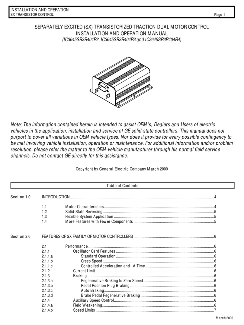
GE IC3645SR3R404R2 User manual

GE

GE IC3645SR3R404R2 User manual

GE PACSystems RX3i IC695ETM001-JW User manual

GE

GE PACSystems RX3i IC695ETM001-JW User manual

GE CR194 User manual

GE

GE CR194 User manual

GE SX TRANSISTOR CONTROL IC3645SR4U404N2 User manual

GE

GE SX TRANSISTOR CONTROL IC3645SR4U404N2 User manual

GE b30 User manual

GE

GE b30 User manual

GE NX-1710E - Single Door Control Module Installation and operation manual

GE

GE NX-1710E - Single Door Control Module Installation and operation manual

GE B90 UR Series User manual

GE

GE B90 UR Series User manual

GE Masoneilan VariPak 28001 User manual

GE

GE Masoneilan VariPak 28001 User manual

GE 10000 User manual

GE

GE 10000 User manual

GE Masoneilan 77-6 User manual

GE

GE Masoneilan 77-6 User manual

GE AV-300i User manual

GE

GE AV-300i User manual

GE ARITECH ATS7300 User manual

GE

GE ARITECH ATS7300 User manual

GE Dialog User manual

GE

GE Dialog User manual

GE VersaMax IC200CHS006 User manual

GE

GE VersaMax IC200CHS006 User manual

GE IC3645SR4W606N6 Owner's manual

GE

GE IC3645SR4W606N6 Owner's manual

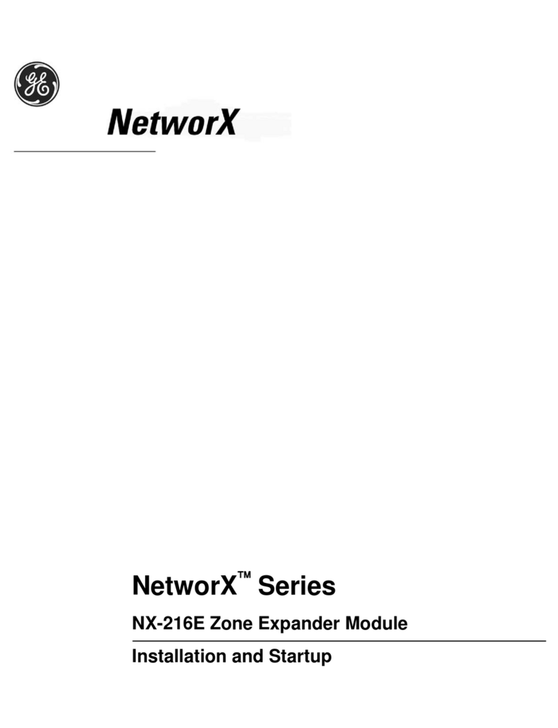
GE NetworX Series Installation manual

GE

GE NetworX Series Installation manual

GE Spectra Series User manual

GE

GE Spectra Series User manual

GE MiCOM P40 Agile User manual

GE

GE MiCOM P40 Agile User manual

GE WH18X28174 Configuration guide

GE

GE WH18X28174 Configuration guide

GE VARIVENT S Series User manual

GE

GE VARIVENT S Series User manual

GE C-800 Series User manual

GE

GE C-800 Series User manual

GE Baker Hughes 2900-40 Series User manual

GE

GE Baker Hughes 2900-40 Series User manual

GE Current Evolve User manual

GE

GE Current Evolve User manual

GE WIU-4 User manual

GE

GE WIU-4 User manual

Popular Control Unit manuals by other brands

Wilo RexaBloc RE Installation and operating instructions

Wilo

Wilo RexaBloc RE Installation and operating instructions

Allen-Bradley ControlNet 1786-RPFRL/B installation instructions

Allen-Bradley

Allen-Bradley ControlNet 1786-RPFRL/B installation instructions

Keysight Technologies M937A Series Demo guide

Keysight Technologies

Keysight Technologies M937A Series Demo guide

Quectel SC200L Hardware design

Quectel

Quectel SC200L Hardware design

Elseta IOMOD 8DI8DO user manual

Elseta

Elseta IOMOD 8DI8DO user manual

GEA ECOVENT N/W operating instructions

GEA

GEA ECOVENT N/W operating instructions

Avaya J100 Series Using instructions

Avaya

Avaya J100 Series Using instructions

Erie 541N Series Technical manual

Erie

Erie 541N Series Technical manual

Cartell CT-2B Installation & operation manual

Cartell

Cartell CT-2B Installation & operation manual

Sauer Danfoss PVG 100 technical information

Sauer Danfoss

Sauer Danfoss PVG 100 technical information

Rtelligent ECT Series user manual

Rtelligent

Rtelligent ECT Series user manual

Motorola Canopy user manual

Motorola

Motorola Canopy user manual

Lamtec ETAMATIC OEM manual

Lamtec

Lamtec ETAMATIC OEM manual

Bray Flow-Tek 7000 Series Installation, operation and maintenance manual

Bray

Bray Flow-Tek 7000 Series Installation, operation and maintenance manual

Singmai Electronics SM08 user manual

Singmai Electronics

Singmai Electronics SM08 user manual

National Instruments 9853 Getting started guide

National Instruments

National Instruments 9853 Getting started guide

Inficon LDS3000 AQ Original operating instructions

Inficon

Inficon LDS3000 AQ Original operating instructions

TLV DR20 instruction manual

TLV

TLV DR20 instruction manual

manuals.online logo
manuals.online logoBrands
  • About & Mission
  • Contact us
  • Privacy Policy
  • Terms and Conditions

Copyright 2025 Manuals.Online. All Rights Reserved.