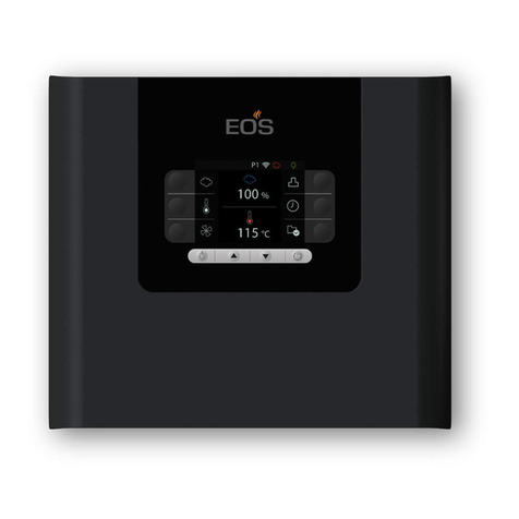
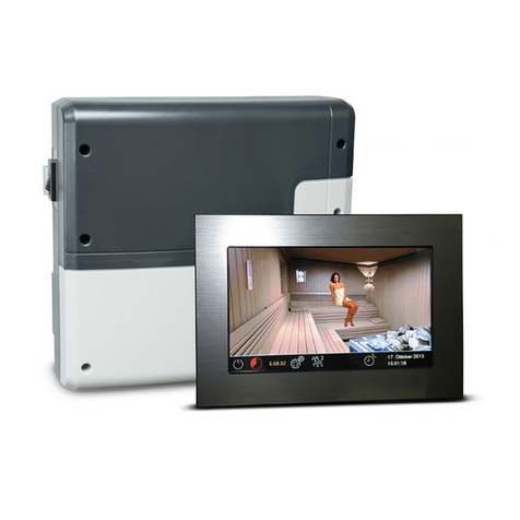
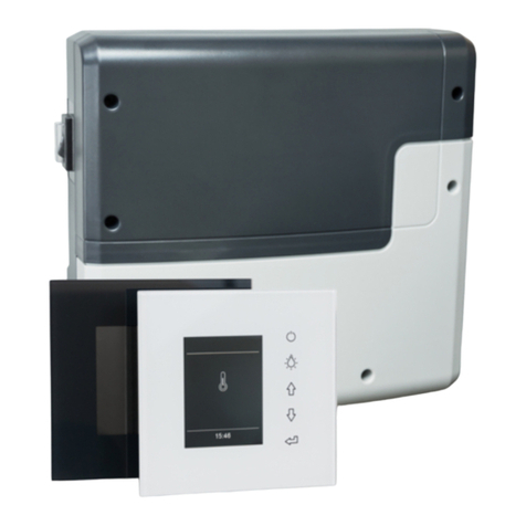
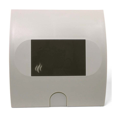
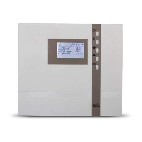
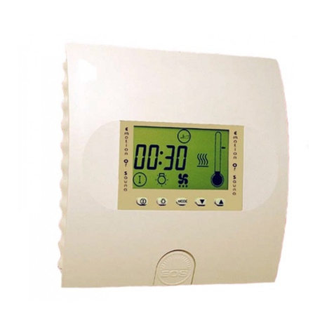
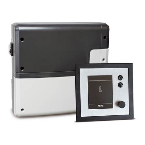
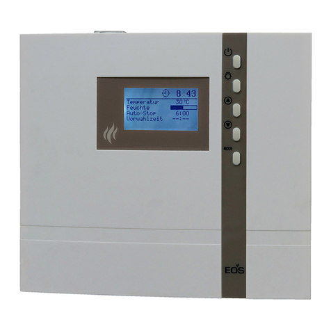
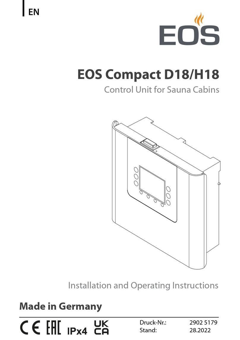
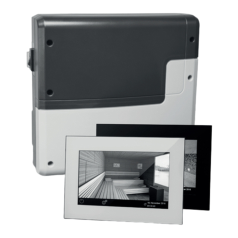
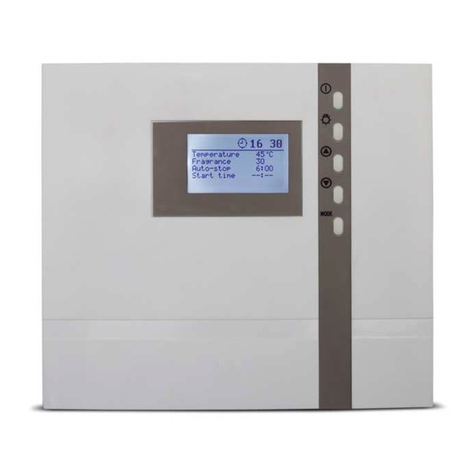
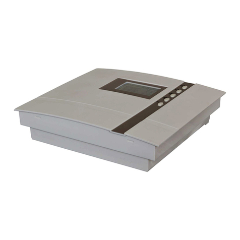
EOS EMOTEC DC 9000 User manual

1
D
IP x4
Made in Germany
GB
Druck Nr. 2934528en / -22.08
User‘s Guide
EMOTEC DC 9000

2GB
English
Table of Contents
Package contents ..................................................................................................3
Technical data. . . . . . . . . . . . . . . . . . . . . . . . . . . . . . . . . . . . . . . . . . . . . . . . . . . . . . . . . . . . . . . . . . . . . . . . . . . . . . . . . . . . . . . . . . . . . . . . . . . . . . . . . 3
General information concerning sauna bathing ......................................................4
General safety precautions. . . . . . . . . . . . . . . . . . . . . . . . . . . . . . . . . . . . . . . . . . . . . . . . . . . . . . . . . . . . . . . . . . . . . . . . . . . . . . . . . . . . . 5
Assembly of the control unit. . . . . . . . . . . . . . . . . . . . . . . . . . . . . . . . . . . . . . . . . . . . . . . . . . . . . . . . . . . . . . . . . . . . . . . . . . . . . . . . . . . . 6
Wall mounting ...................................................................................................6
Electrical connection .........................................................................................7
Connecting the sauna oven ..............................................................................7
Connecting the sauna lamp ..............................................................................7
Connecting the sensor lines..............................................................................8
Mounting the oven sensor.................................................................................8
Operation .. . .. . . . . . . . . . . . . . . .. . .. . .. . .. . . . . . . . . . . . . . . .. . .. . .. . .. . . . . . . . . . . . . . . .. . .. . .. . .. . . . . . . . . . . . . . . .. . .. . .. . .. . . . . . . . 9
Button functions ................................................................................................9
Symbol description. . . . . . . . . . . . . . . . . . . . . . . . . . . . . . . . . . . . . . . . . . . . . . . . . . . . . . . . . . . . . . . . . . . . . . . . . . . . . . . . . . . . . . . . . . . . 9
Switching on the device for the first time ..............................................................10
Default parameters..........................................................................................11
Finnish sauna operation..................................................................................11
Temperature indicator .....................................................................................11
Heating time....................................................................................................11
Please note the following when programming the unit .........................................12
Specialist section .. . . . . . . . . .. . . . . . . . . .. . .. . . . . . . . . .. . . . . . . . . .. . .. . . . . . . . . .. . . . . . . . . .. . .. . . . . . . . . .. . . . . . . . . .. . .. . . . . 13
F1 Setting the current time..............................................................................13
P1 Start with preset time. . . . . . . . . . . . . . . . . . . . . . . . . . . . . . . . . . . . . . . . . . . . . . . . . . . . . . . . . . . . . . . . . . . . . . . . . . . . . . . . . 14
P2 Preset time mode.......................................................................................15
P5 Temperature setting . . . . . . . . . . . . . . . . . . . . . . . . . . . . . . . . . . . . . . . . . . . . . . . . . . . . . . . . . . . . . . . . . . . . . . . . . . . . . . . . . . . 16
P6 Programming fan operation .......................................................................17
P7 Ability to dim the cubicle lights. . . . . . . . . . . . . . . . . . . . . . . . . . . . . . . . . . . . . . . . . . . . . . . . . . . . . . . . . . . . . . . . . . . 18
Coloured light (optional). . . . . . . . . . . . . . . . . . . . . . . . . . . . . . . . . . . . . . . . . . . . . . . . . . . . . . . . . . . . . . . . . . . . . . . . . . . . . . . . . . 19
P9 Setting the time interval for the coloured light. . . . . . . . . . . . . . . . . . . . . . . . . . . . . . . . . . . . . . . . . . . . 21
The control unit switch (Switch-off) . . . . . . . . . . . . . . . . . . . . . . . . . . . . . . . . . . . . . . . . . . . . . . . . . . . . . . . . . . . . . . . . . . . . . . 22
Changing the heating time limitation for commercial use .....................................22
Error display. . . . . . . . . . . . . . . . . . . . . . . . . . . . . . . . . . . . . . . . . . . . . . . . . . . . . . . . . . . . . . . . . . . . . . . . . . . . . . . . . . . . . . . . . . . . . . . . . . . . . . . . . . 23
Other error options that are not displayed and their causes: ..........................23
Connection diagram. . . . . . . . . . . . . . . . . . . . . . . . . . . . . . . . . . . . . . . . . . . . . . . . . . . . . . . . . . . . . . . . . . . . . . . . . . . . . . . . . . . . . . . . . . . . . . 24
Handling procedures for return shipments (RMA) - Details for all returns ! . . . . . . . . . . 25

3
GB
Technical data
Nominal voltage: 400 V 3 N AC 50 Hz
Switching load: max. 9 kW Ohm resistive load (AC1 - mode)
device can be extended by connecting powered control units
upto 36 kW
Heating time limit: 6hr, 12 hr or no heating time limit
Display: Jumbo backlit LCD
Protection class: IPx4 in line with DIN 40050 splashed water resistant
Normal range for sauna: 30 to 110°C
Sensor system: KTY sensor with safety temperature limiter 142°C
Control characteristic: digital two-point regulation
Fan output: min. 25 W max.100 W (only fan excluding capacitor)
Light: min. 25 W max.100 W (only Ohm resistive load)
Coloured light (optional): max. 100 W per colour
Colour on-time: 1- 10 min
Colour order: red - red/yellow - yellow - yellow/green - green - green/blue - blue
-blue/red
Error display: via warning triangle (flashing) and error code on LCD
Ambient temperatures: -10°C to +35°C
Storage temperatures: -20°C to +60°C
Fuse protection on the light and the ventilation can
be a maximum of 1A delay action. There is a danger
of fire if greater fuse protection is used!
Package contents
(subject to change)
Included with the control unit are:
1. An heater-sensor board with overheat shutoff protection, KTY-sensors with sensor hou-
sing , two 3x25 mm fastening screws and a 1,7 m long sensor cable, red and white.
2.A plastic bag with three 4 x 20 mm fastening screws.
3.A replacement overheat protection module.

4GB
Dear customer,
with purchase of this sauna control unit you
opted for a superior quality, high-tech elec-
tronic device which was developed and
manufactured according to the highest stan-
dards and guidelines.
Please note that an optimal interaction of
sauna cabin, sauna oven and sauna control
unit is mandatory for a pleasant sauna cli-
mate in your cabin.
With this superior sauna control unit you can
„operate“ your sauna system, and thanks to
the many individual programming settings
you will surely soon find the setting that suits
you best.
Perception in the sauna is very subjective,
therefore it really requires your own percep-
tion, or that of your family to find the most
suitable settings.
By default the finnish sauna is preset to
95°C. For steam operation the values are
set to 60°C and 60% humidity.
The following operation instructions describe
how to pre-select „your“ climate in the cabin.
Read these instructions carefully, so that you
quickly and easily find your way though the
programming process.
Please note the variation in temperatures in
the cabin while sauna bathing. The hottest
area is directly under the cabin ceiling, whe-
reas there is a steady temperature gradient
towards the floor of the cabin. Inversely, the
relative humidity is lowest directly under the
cabin ceiling and the highest on the cabin
fl o or.
For safety reasons the temperature sensor
with the overheat safety shutdown is located
on the cabin ceiling above the oven, since
this is the hottest area in the cabin.
Therefore there will always be temperature
variations between the temperature sensor
of the control unit and the thermometer in
the cabin.
General information concerning sauna bathing
For the cabin light use only light bulbs. Do
not use fluorescent lamps, energy saving
lamps and gas discharge lamps.
For example, when pre-setting the cabin
temperature to 100°C, the thermometer in-
side the cabin may easily show 85°C - 90°C.
This complies with the typical climate inside
the cabin.
Always observe hygiene. Always use hand-
or bathing towels, to avoid getting perspirati-
on on the wood.
To protect your cabin from possible dama-
ges due to steam operation, we recommend
reheating or drying the cabin after every
steam bath.
In addition, a fan can help to dissipate used
humid air in badly ventilated areas.
To avoid the perception of draft, you should
avoid using any ventilation system while
sauna bathing. It should only be used if re-
commended by the cabin manufacturer
Always make sure no objects are
located on the sauna oven before
starting the heating cycle.
5
GB
General safety precautions
•his device has not been designed for being
used by persons (including children) that
are physically or mentally handicapped
or have sensory disabilities. Moreover, it
is not allowed to use this device without
sufficient experience and/or knowledge,
unless these persons will be supervised
by persons responsible for their security
or in case they have been instructed how
to use this device.
• Children are to be supervised in order to
make sure that they do not play with this
device.
• Attention: It is forbidden to install
the control box in a closed switch ca-
binet or behind a wooden panelling!
• The electrical installation may be done
only by a qualified electrical technician.
• You must comply with the regulations of
your power supply company and applica-
ble VDE regulations (DIN VDE 0100).
• WARNING: Never attempt repairs
orinstallations yourself, as this could
result in serious injury or death. Only a
qualified technician may remove the hou-
sing cover.
• Please note the dimensions in the assem-
bly instructions, especially when installing
the temperature sensor. The temperature
above the oven is critical for the tempera-
ture setting. The temperature can be held
within operating parameters and a mini-
mal temperature gradient inside the bench
area of the sauna cabin can be achieved
only if unit is assembled correctly.
• The device may only be used as intended
as a control unit for sauna ovens up to 9
kW. (Up to 36 kW when combined with a
breaking capacitor).
• Completely disconnect the control unit
from the electrical circuit, i.e. flip all circuit
breakers or the main circuit breaker during
each installation or repair.
• Please note the safety and installation in-
formation from the sauna oven manufac-
turer.
• Always heed the specifications and in-
structions of the cabin manufacturer, too.

6GB
Assembly of the control unit
Wall mounting
Mount the control unit outside the sauna
cabin only. The most practical mounting
point would be the wall area onto which
the sauna oven is mounted on the inside,
except on the outside of the cabin. If elec-
trical conduits are present, mount the con-
trol unit accordingly. To mount the control
unit, please follow these instructions:
Illust. 1
1. Remove the cover of the control unit. To
do this press the fastening tab inwards
with a flat screwdriver and remove the
housing top by pivoting it upwards (Il-
lust.1). Drill the threaded holes for the
included 4 x 20 mm wood screws accor-
ding to Illust. 3 & 3.1.
2.Insert one of the wood screws into the
upper middle hole. This screw will be the
mounting point for the control unit. Make
sure the screw is projecting out from wall
about 3 mm. (Illust. 3.2)
3.Hang the control unit onto the 3 mm pro-
jecting screw. Insert the included rubber
sleeves into the openings on the back
side of the housing and lead the electri-
cal cable through these openings. Screw
the lower part of the housing onto the ca-
bin wall using the lower threaded holes.
(Illust. 4)
Illust. 3
eye level
Illust . 3.2
3
Illust . 4
feed-through channel for
power supply lead wire
oven supply line
vaporizer supply line
lamp
fan
feed-through
channel for
sensor lines
upper threaded hole
threaded holes
Illust. 3.1
ca. 34 cm
17,4 cm
19 cm
eye level

7
GB
minimum diameter in mm² (copper wire) connection to 380 V 3N AC
Connector
capacity
in kW
Appropriate for
cabin sizes
(in m³) Power supply lead wire
to the control unit Connector cable con-
trol unit for oven
safety fuse
capacity in A
4,5 4 - 6 5 x 2,5 mm² 5 x 1,5 mm² 3 x 16
6,0 6 - 10 5 x 2,5 mm² 5 x 1,5 mm² 3 x 16
7,5 8 - 12 5 x 2,5 mm² 5 x 1,5 mm² 3 x 16
9,0 10 - 14 5 x 2,5 mm² 5 x 1,5 mm² 3 x 16
GIn general, there can only be one per-
manent connection to the power supply
network, to include a device which allows
the unit to be disconnected from the power
source with a contact distance of at least 3
mm from all terminals.
All electrical installations and connector
cables inside the cabin must be able to
withstand temperatures up to 142°C. Ple-
ase use the table below to determine the
required cable diameters for this task.
Attach the power supply lead wire as shown
in Illust. 5 to the power supply terminals of
the control unit. Connection instructions
are printed directly in the control unit.
Lead wire for cabin
lighting
Air intake opening Illust. 5
Power supply
lead wire
Connecting the sauna oven
Assemble the sauna oven according to the
instructions provided by the manufacturer
in front of the air intake opening.
Lead the silicon lines through the electrical
conduits to their respective terminals on the
control unit and connect them according to
the circuit diagram printed there.
Please note: If no electrical conduits are
present, drill a hole with a diameter of 10
mm next to the air intake opening and lead
the oven control cables through this hole
to their corresponding terminals (U V W) in
the control unit. To protect the silicon lines
from external influences, install them in a
shielded fashion. For this task, use a fitting
cable or simple PVC conduit and lead the
silicon cable through it to the control unit.
Connecting the sauna lamp
The sauna lamp must be splashproof (by
Standard IPx4) and resistant to ambi-
ent temperature. The sauna lamp can be
mounted anywhere except in the area of
the rising hot air above the oven.
Electrical connection
The electrical connection may
only be done by a qualified elec-
trical technician under authority of the
regulations of the local power supply
company and those of the VDE.

8GB
20 cm
Illust. 7
Illust. 8 Illust. 9
Connecting the sensor lines
ou should not install sensor and power sup-
ply lines together, or lead them through the
same conduit. This can lead to interferences
in the electronics, such as „fluttering“ in the
relays. If it is absolutely necessary to install
them together, or the wire is longer than 3m,
you should use a shielded sensor line such
as the LIYLY-O x 0.5 mm²). Connect the
shielding to mass in the control unit.
Please note that the following measure-
ments are based on values provided by the
unit quality assurance by the European Stan-
dard EN 60335-2-53. In principle, you must
mount the oven sensor where temperatures
are expected to be the highest. Illust. 7 gi-
ves you an overview of the mounting point of
the sensor..
Mounting the oven sensor
1. Mount the oven sensor in cabins up to 2
x 2m according to Illust. 7 and 8, in larger
cabins according to Illust. 7 and 9.
2.Drill a hole to lead the cable through, pre-
ferably through the middle of one of the
wooden boards.
3.Lead the sensor cable through the drilled
hole and attach it to the sensor line accor-
ding to Illust. 10.
4. Attach the lines for the shutoff (white) and
the temperature sensor (red) according to
Illust. 11 to the sensor board. Then insert
the sensor board into the housing.
5.After you are finished installing and have
made sure the control unit is functioning
properly, check the line for overheat shu-
toff protection for short circuits. To do this,
release one of the white lines in the sensor
housing. The safety relay of the control
unit should now fall; i.e. the heating circuit
should now be interrupted.
Hole
Sauna ceiling
Center sensor housing
on middle section
Sensor line
Terminals in the
control unit
Illust. 10
Ô
Housing
red
red
Sensor-
board
Illust. 11
Sensor
white (Limiter
white (Limiter)

9
GB
Button functions
Operation
Symbol description
TimeF1
P1 Preselected time
P2 Heating time
P5 Heating (dry)
Error message
P6 Ventilation function
P7 Lamp
P9 Coloured light
Operating
switch on - off Lamp
on - off Program button Selection
buttons
Mode
If the control box does not pick off voltage after closure, please check the position of
the control box switch (Switch-Off). See chapter about „control box switch (Switch-Off)
„at the end of this manual.

10 GB
Switching on the device for the
first time
After checking all the connections once
again, connect the device to the mains by
switching on the fuses or mains switch.
The time appears on the display.
12:03
20:03
20:03
20:03
06:00
Afterwards the displays shows „F1“ for
short time.
Afterwards the display shows the present
time. The unit is ready to use.
The device is switched on via the „„but-
ton. This also switches on the cubicle and
screen lighting.
On the display appears
Please confirm with the „Mode“ button.
Please chose the wished value with the „
„ and „ „Please chose the wished value
with the
20:03
If the display flashes, proceed as follows:
Refer to chapter „F1“ of the operating in-
structions for information on changing the
time setting.

11
GB
Pre-selected
temperature
Actual temperatu-
re in the cubicle
20:03
05:58
20:03
05:58
Default parameters
Finnish sauna operation
After switching on the screen displays the
current time and remaining heating time
alternately.
Temperature indicator
The temperature is indicated on the right
side of the screen above the thermometer
icon.
Here the pre-selected temperature is
indicated by an arrow to the right of the
thermometer.
The temperature in the cubicle is shown by
the rising thermometer.
When heating the cubicle the thermometer
fi l ls up to the pre-selected temperature. Then
the control phase starts.
Heating time
the factory setting limits the heating time
to 6 hours. This means that after switching
on, the device switches off after 6 hours for
safety reasons.
The remaining heating time is displayed
on the screen alternately with the current
time.

12 GB
The buttons to be used are shown in the text as follows.
Symbols shown in the display sketches as follows will flash on the display.
JEvery change to the set parameters must be confirmed and saved by pressing the „Mode“
button. The new values set flash briefly before the unit switches back to the basic display.
If you change the parameters without saving them with the „Mode“ button, the previous
values automatically remain active.
If you do not operate the unit for a longer period when programming, the display switches
back automatically to the basic display, and the background lighting switches off after a short
time.
The sauna switches off automatically at the
end of the selected heating time.
If you want to end your sauna before this
time, press the „
„ button. The sauna
is switched off. The screen indicates the
current time.
Please note the following when programming the unit
= „ „
= „ „
= „Mode“
= „ „
= „ „
The many programming facilities of the unit are divided basically into:
MODE
Programmierebenen
Specialist levels These levels are indicated by „F1 - F 6“. Depending on the unit type,
it may be that certain individual levels are not displayed.
Parameters that only have to be changed very rarely in daily use
can be changed here. These are set following initial installation, and
then usually remain unchanged, at least for an extended period.
These levels are indicated by „P 1 - P 9“. Depending on the unit
type or the set operating mode, it may be that certain individual
levels are not displayed.
Parameters that are changed often to meet your individual require-
ments in daily use can be changed here.
20:03

13
GB
Specialist section
F1 Setting the current time
F 1
20:03
21:03
21:03
For clock time adjustment please press
„Mode“ and „ “ button synchron.
(In the display appears „F1“ and the clock
symbol.)
Please confirm with the „Mode“ button.
Please chose the wished value with the
„ „ and „ „ buttons.
(to switch between summer and winter
time for example)
Please confirm with a long press on the
„Mode“button until the new value is flashing
on the display.
Afterwards the displays shows „F1“ for
short time

14 GB
Use the buttons „ „ and „ „ to set the
required value in 10 minutes steps.
Please consider that the cubicle must heat
up for around 40-50 minutes to achieve an
appropriate temperature. If, for example, you
want to start your sauna at 18.00 select the
preset time to 17.10.
Please confirm with a long press on the
„Mode“button until the new value is flashing
on the display.
The P1 program function is displayed on the
screen briefly.
While P1 is displayed on the screen press
the button until the preset time icon flas-
hes. This starts the preset mode.
Programming section
P1 Start with preset time
You can use the time pre-selection to start your sauna within the next 24 hours.
Always ensure that no objects are located on the sauna heater at the start of
the heating process. Risk of fire!
P 1
15:07
17:10
P 1
17:10
20:03 17:10
For the heating adjustment please press
„Mode“button. In the display appears the
pre heating time symbol and „P1“.
Please confirm with the „Mode“ button.
After a short time the screen displays the
current time and preset heating time alter-
nately. The screen’s background lighting
goes out.
When the preset time is reached the sauna
equipment switches itself on. At the end of
the heating period the control unit automati-
cally switches the device off.

15
GB
P2 Preset time mode
P 2
06:00
03:00
03:00
The heating time limiter is fixed at 6 hours.
After these time the sauna will automatic
shut-off.
For the heating time limiter adjustment ple-
ase press „Mode“ button.
Afterwards the „ „ button until in the dis-
play the the heating time symbol and „P2“
appears.
Please confirm with the „Mode“ button.
Please chose the wished value with the
„ „ and „ „ buttons.
Please confirm with a long press on the
„Mode“button until the new value is flashing
on the display.
Afterwards the displays shows „P2“ for short
time. The heating time limiter is now fixed
with the new value.

16 GB
Attention:Temperature range
in Finnish operation 30-110 C
in humidity operation 30-70 C
P 5
95
85
85
P5 Temperature setting
The temperature is fixed on 95C for Finnish
operation and 60C for Humidity operation.
For temperature adjustment please press
„Mode“ button.
Afterwards the „„button until in the display
the heating symbol and „P5“ appears.
Please confirm with the „Mode“ button.
Please chose the wished value with the
„ „ and „ „ buttons.
The arrow at the thermometer-symbol
shows the selected temperature-area.
Please confirm with a long press on the
„Mode“button until the new value is flashing
on the display.
Afterwards the displays shows „P5“ for
short time. Temperature is now fixed with
the new value.

17
GB
P 6
Level 0 fan off
Level 1
Level 2
Level 3
2
2
0
P6 Programming fan operation
This control unit gives you the option of swit-
ching on a fan (max. 100W) and setting the
fan speed individually to one of 3 stages.
The default setting is „no fan mode“. Only
in post heating operation after operation
humidity the fan is default on the maximum
step.
For fan function adjustment please press
„Mode“ button.
Afterwards the „ „ button until in the display
the fan symbol and „P6“ appears.
Please confirm with the „Mode“ button.
Please chose the wished value with the „
„ and „ „ buttons.
They mean:
0 = fan off
1 = fan level 1 (approx. 1/3 output)
2 = fan level 2 (approx. 2/3 output)
3 = maximum fan output
Please confirm with a long press on the
„Mode“button until the new value is flashing
on the display.
Afterwards the displays shows „P6“ for
short time. Fan function is now fixed with
the new value.
The selected level can be seen by the points
under the fan icon on the screen.

18 GB
P7 Ability to dim the cubicle lights
100
P 7
80
80
Please note that this function may only be
programmed in combination with incande-
scent bulbs. No phosphorous,energy-
saving or gas discharge bulbsmay be
used.
The default light setting is maximum. You
can dim the cubicle lighting of your sauna
as you wish.
For illumination power adjustment please
press „Mode“ button.
Afterwards the „…“ button until in the display
the light symbol and „P7“ appears.
Please confirm with the „Mode“ button.
Please chose the wished value with the
„ „ and „ „ buttons.
Please confirm with a long press on the
„Mode“button until the new value is flashing
on the display.
Afterwards the displays shows „P7“ for short
time. Illumination power is now fixed with
the new value.

19
GB
Press the „ „ button for approx. 5
seconds. The coloured light symbol and the
number 0 appear on the display.
This programming option is only available if the coloured light module (item
number 942761) has been installed.
Coloured light (optional)
Switch off all power to the system before installing the coloured light mo-
dule.
Switching on the coloured light
0
You have the option of operating a coloured light device in your sauna using the HCS 9003
control unit. Each coloured light may not exceed the maximum power of 100 W.
1
20:03
red
yellow
green
blue
Please chose the wished value with the „
„and „ „ buttons.
They mean:
0 = off
1 = automatic mode
2 = permanent red
3 = permanent yellow
4 = permanent green
5 = permanent blue
When the coloured light is switched on the
screen also displays the flashing coloured
light icon.
The coloured light icon indicates the seg-
ment for the colour that is currently lit.
The colours are assigned as follows.

20 GB
20:03
If coloured light mode is to be switched off
use the previous instructions and set the
value to „0“.
It goes without saying that the sauna
lights can also be switched on and off in
coloured light mode. To do so press the
light switch as usual.
IIf the sauna light is on the coloured light icon
does not flash but is shown constantly.
Other manuals for EMOTEC DC 9000
2
This manual suits for next models
1
Table of contents
Other EOS Control Unit manuals
Popular Control Unit manuals by other brands

Samson
Samson 3222 Series Mounting and operating instructions

Pfeiffer Vacuum
Pfeiffer Vacuum HPU 001 operating instructions

HELIX
HELIX GRANVILLE-PHILLIPS Convectron ATM instruction manual

Tyco
Tyco CCU/232-NIM Install instructions

Telit Wireless Solutions
Telit Wireless Solutions G30 Hardware user's guide

VMIC
VMIC VMIVME-7453 manual