EWC Controls PRD Service manual

Model PRD & PRD- RD
TB-224
P/N 090375A0224 REV. M
Leave this bulletin on the job site for future reference!
EWC Controls Inc. 385 Highway 33 Englishtown, NJ 07726 800-446-3110 FAX 732-446-5362 E-Mail- [email protected] 1
Copyright 2006-2008 EWC Controls All Rights Reserved©
Barometric By-Pass Damper
GENERAL DESCRIPTION
Note: This drawing of the Bypass damper, Hand Damper, Static Pressure control and Related duct work is intended to serve only as a guide.
Your actual duct work layout and components may differ. Use the graphic as a guide when planning or designing a Zone system regardless of
the Equipment type, Duct layout and Airflow configuration.
Supply Air
to
Zone Dampers
Pitot Tube
Ultra-Zone™PS4
Static Pressure Control
EBD
MotorActuatedorBarometric
PRD orPRD - RD
ByPassDamper
3/8” O.D.
Reference Tubing
Ultra-Zone™
Ultra-Zone™
HVAC
UNIT
Return Air
from
All Zones
Ultra-Zone™
Zone Control
Panel
24vac Power
Control Wiring
Supply
Air
Sensor
(required)
RD-HD
SID-HD
ND-HD
Hand
Damper
Return
Air
Sensor
(optional)
MP
Ultra-Zone™
6ft. if possible 6ft. if possible
-
The model PRD & PRD-RD pressure regulating dampers are a single blade rectangular or round barometric damper
assemblies with a counter balanced weighted arm. The barometric by-pass damper is an economical way to manage
airflow when zone dampers close. Damper adjustment is achieved by off-setting the hex shaped arm, securing
weight #1 towards the bottom of that arm and moving the extra weight(s) (optional) up or down the arm, until the
correct bypass flow is achieved. See Page 2 for details. For field versatility, the hex shaped arm can be inserted into
either side of the damper. Additional weights can be added if necessary.
The barometric by-pass damper is installed in the duct-work to regulate excess air pressure and volume. The damper
can be mounted to relieve pressure by returning the air back to the return air duct or by dumping it into a non-critical
conditioned area. A restricting hand damper can be installed downstream of the by-pass damper, which allows the
installer to set sufficient differential pressure across the bypass duct, controlling how fast the by-pass air mixes with
return air. See Application Note 090376A0169D.
The PRD & PRD-RD are effective By-Pass solutions for any Constant Speed or Variable Speed Zoned HVAC system
up to 4 ton capacity.
MODEL # SIZE
BYPASS Cfm*
560 Cfm
700 Cfm
825 Cfm
900 Cfm
1125 Cfm
1375 Cfm
12" x 8"
12" x 10"
12" x 12"
20" x 8"
20" x 10"
20" x 12"
PRD 12 x 8
PRD 12 x 10
PRD 12 x 12
PRD 20 x 8
PRD 20 x 10
PRD 20 x 12
# WEIGHTS
2
2
2
2
2
2
* CFM @ 900Fpm
(.15”wc friction loss)
BYPASS Cfm*
850 Cfm
1100 Cfm
1300 Cfm
1300 Cfm
1750 Cfm
2000 Cfm
* CFM @ 1400Fpm
(.3”wc friction loss)
MODEL #
BYPASS Cfm*
320 Cfm
500 Cfm
720 Cfm
950 Cfm
1250 Cfm
8"
10"
12"
14”
16"
PRD-RD 8
PRD-RD 10
PRD-RD 12
PRD-RD 14
PRD-RD 16
# WEIGHTS
1
1
1
2
2
BYPASS Cfm*
500 Cfm
750 Cfm
1100 Cfm
1400 Cfm
1900 Cfm
Use the Cfm tables provided below to size your by-pass damper using the guideline provided on the next page. Use
the 1400Fpm column to achieve smaller bypass runs at higher velocities. Use the 900Fpm column if you have the
space to accommodate a large bypass run at a nominal velocity.
SIZE
* CFM @ 1400Fpm
(.3”wc friction loss)
* CFM @ 900Fpm
(.15”wc friction loss)

EWC Controls Inc. 385 Highway 33 Englishtown, NJ 07726 800-446-3110 FAX 732-446-5362 E-Mail- [email protected]
2
BYPASS SIZING CALCULATIONSBYPASS SIZING CALCULATIONS
The bypass damper must be installed horizontal & level between the supply duct and the return duct.
Position the damper to open in the direction of airflow back to the return duct or into a conditioned area.
Place the duct connection on the return so that the bypass air has a minimum 6 feet of return duct. before it
enters the air handler, if space permits. If a Restricting Hand Damper is installed, it should have been setup
already. If not, refer to Application note 090376A0169D. Otherwise, close the hand damper ½ way.
Position the ARM in the “IDEAL ARM LOCATION” for the correct direction of air flow and tighten the
thumb screw. (Refer to page 4)
Position the Extra Weight (optional) high up on the ARM and tighten the thumb screw. Position Weight#1
towards the bottom of the arm and tighten the thumb screw. (Refer to page 3)
Energize ALL Zones to operate the unit with the Fan running on the Highest speed. (Usually a Cooling
demand, 2nd stage if applicable)
Return to the damper & confirm that the by-pass damper is closed. If necessary, reposition the Extra Weight
or Weight #1 lower on the ARM until the damper closes completely. (It should be closed to the point where
any additional force will start to open it) (Refer to page 3)
Turn off all Zones but the Smallest Zone & Wait about 45 seconds.
Monitor the airflow for the Smallest Zone. Is there to much Airflow or Noise? Proceed to Step 9.
Is there Insufficient Airflow? Proceed to Step 10.
Is the Airflow Acceptable? Proceed to Step 11.
Excess Velocity: Reposition the Extra Weight higher up on the ARM until the velocity in the smallest zone
has subsided to an acceptable level. If the velocity remains high, reposition Weight #1 higher up on the arm,
or if necessary, reposition the ARM closer towards “6 or 0” on the scale. (Depending on the model).
Insufficient Velocity: Reposition the Extra Weight lower on the ARM until the velocity is at an acceptable
level. If the velocity remains low, reposition the ARM closer towards the “3 or 9” on the scale ((Depends on
model. Refer to page 3&4) depending on direction of flow). If velocity still remains low for the smallest zone, to
much air is being forced through the barometric damper. You can order additional weights or you should
consider installing an Electronic By-Pass Damper (Model EBD).
Congratulations, your PRD By-Pass damper is now properly adjusted.
1.
2.
3.
4.
5.
6.
7.
8.
9.
10.
11.
BAROMETRIC BYPASS SET-UP PROCEDUREBAROMETRIC BYPASS SET-UP PROCEDURE
Start with the system’s Total Cfm (2000Cfm) 3 zone system (Zone 1 = 750Cfm, Zone 2 = 750Cfm, Zone 3 = 500Cfm plus 4 open runs @ 50Cfm)
Calculate the Cfm for the smallest zone that can run by itself (500Cfm)
Calculate the Cfm for any non-dampered (open) duct runs (4 x 50Cfm = 200 Cfm)
Calculate Damper stop leakage (20%) on both inactive zones (750cfm x .20 = 150 x 2 = 300Cfm)
Subtract all values from total Cfm (2000 - 500 - 300 - 200 = 1000 Cfm bypass flow)
The left over amount is the bypass Cfm. Refer the bypass Cfm to the chart on Page 1, match to the closest size. If you don’t have enough room for
that size, then go down one size. By-pass velocity will increase on smaller bypass ducts. Regardless of the bypass size, consider installing a
Restricting Hand Damper after the Bypass damper, in order to set sufficient differential pressure and control how fast the bypass air mixes with
the return air. (See graphic on page 1)
EXAMPLE: 5 ton system @ 400 Cfm Per ton = 2000 Cfm 2000 Cfm
Subtract Smallest Zone = 500 Cfm -500 Cfm
Subtract Damper Stop Leakage = 300 Cfm -300 Cfm
Subtract Open Runs = 200 Cfm -200 Cfm
1000 Cfm
1000 Cfm @1400Fpm = 12x10 PRD
or
1000 Cfm @ 900 Fpm = 20x10 PRD
1.
2.
3.
4.
5.
6.
BAROMETRIC BY-PASS SET-UP PROCEDUREBAROMETRIC BY-PASS SET-UP PROCEDURE
EWC Controls Inc. 385 Highway 33 Englishtown, NJ 07726 800-446-3110 FAX 732-446-5362 E-Mail- [email protected] 3
The direction of airflow can
be reversed on the PRD if
Contact EWC Controls Inc.,
Technical support if
necessary for further details.
necessary, by pushing the
Door over the stop on the
bottom of the damper frame.
Then, adjust the arm to the
proper position based on the
new airflow direction.
3
4
5
6
7
8
9
POSITION ARM IN IDEAL LOCATION IF
AIR FLOW IS IN DIRECTION INDICATED
BY THE ARROW ABOVE
IDEAL ARM
LOCATION
IDEAL ARM
LOCATION
AIRFLOW AIRFLOW
POSITION ARM IN IDEAL LOCATION IF
AIR FLOW IS IN DIRECTION INDICATED
BY THE ARROW ABOVE
ARM
GRADUATED
ADJUSTMENT
SCALE
THUMB
SCREWS
IDEAL
ARM
LOCATION WEIGHT #1
EXTRA WEIGHT
IDEALARM
LOCATION
AIRFLOW
POSITION ARM
INIDEAL
LOCATION
0
1
ModelPRD- RDRoundBypassDamper
IDEAL
ARM
LOCATION
WEIGHT#1
THUMB
SCREWS
ARMGRADUATED
ADJUSTMENT
SCALE
EXTRAWEIGHT
Model PRD-RectangularBypassDamper
This arm position reflects
Air-flow from Left to Right!
This arm position
reflects Air-flow from
Right to Left!

EWC Controls Inc. 385 Highway 33 Englishtown, NJ 07726 800-446-3110 FAX 732-446-5362 E-Mail- [email protected]
4
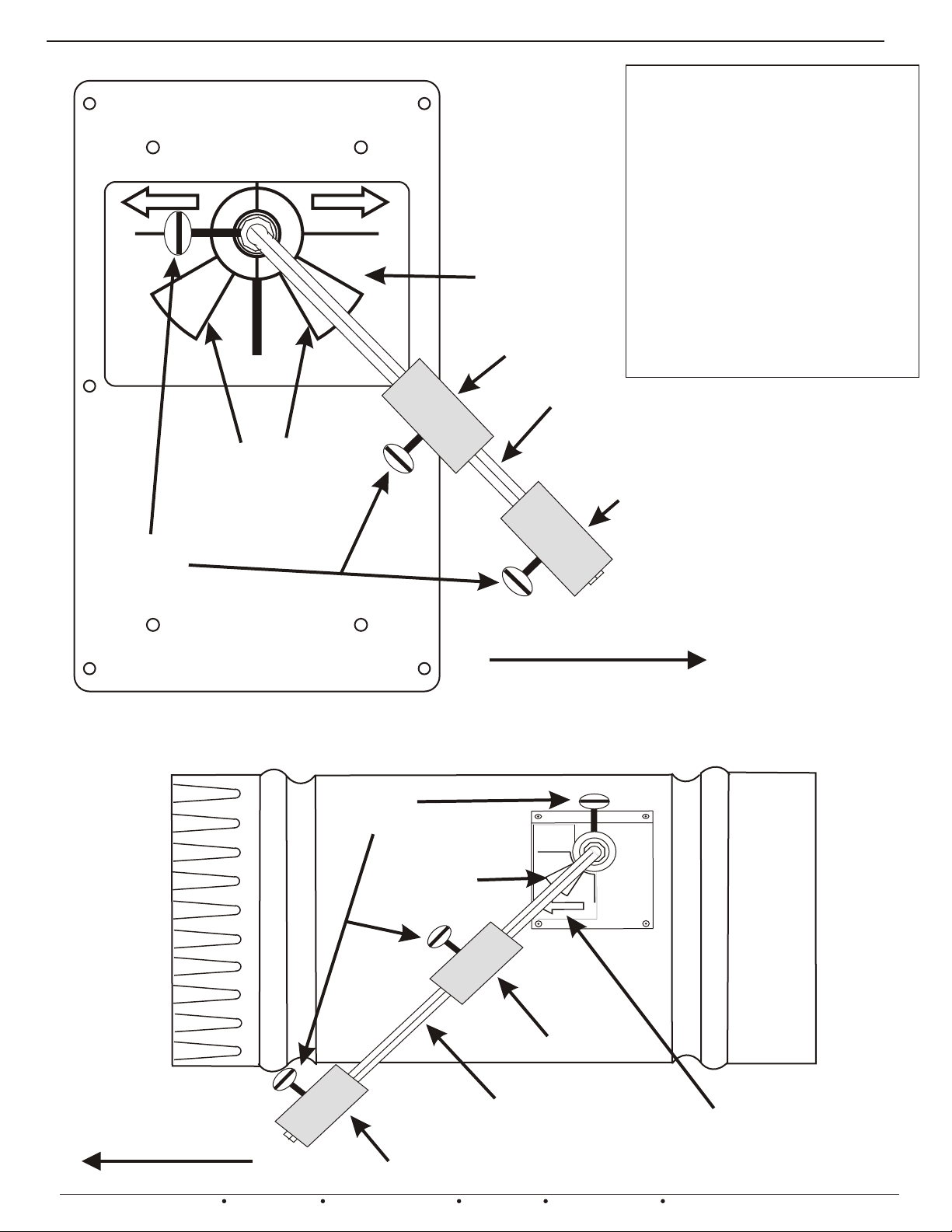
BAROMETRIC BY-PASS DAMPERBAROMETRIC BY-PASS DAMPER
ASSEMBLY OF PRD & PRD-RD BY-PASS DAMPER
1 - INSTALL BY-PASS DAMPER PER INSTRUCTIONS ON PAGE 2.
2 - SLIDE LOCKING-COLLAR OVER DAMPER SHAFT.
3 - INSERT HEX ARM INTO DAMPER SHAFT.
4 - ALIGN LOCKING-COLLAR THUMB SCREW WITH ONE OF THE 4 HOLES ON THE DAMPER
SHAFT WHILE HOLDING ARM AT THE DESIRED ANGLE.
5 - TIGHTEN THUMB SCREW TO SECURE HEX ARM IN PLACE.
6 - POSITION WEIGHT ON HEX ARM AND TIGHTEN THUMB SCREW TO SECURE IN PLACE.
7 - REFER TO PAGE 2 FOR SET-UP PROCEDURE.
THUMB SCREW
LOCKING-COLLAR
DAMPER SHAFT
HEX-ARM
FIGURE 3 -- CUT AWAY VIEW OF ASSEMBLY
FIGURE 4 -- CLOSE-UP VIEWS OF ASSEMBLY
This manual suits for next models
1
Popular Fire And Smoke Damper manuals by other brands


Greenheck
Greenheck EHH-401 Installation, operation and maintenance manual

Krantz
Krantz RK-F10 manual

Trox Technik
Trox Technik FKA2-EU Installation and operating manual

Gryfit
Gryfit LX-5 Installation and usage manual

Tamco
Tamco AIR-IQ Installation guidelines

Schako
Schako BSK-EN Installation, mounting and operating instructions