Gryfit CX-5C Setup guide

IMU-BPP-030-C-2017.08.17 - 1/6
CIAT Sp. z o.o. – ul. Langiewicza 62 – 95-050 Konstantynów Łódzki – POLAND
tel.: (48) 91 432 35 20 – fax: (48) 91 432 35 36 – e-mail: [email protected] – www.gryfit.com
INSTALLATION AND USAGE MANUAL
Manufacturer: CIAT Sp. z o. o. – ul. Langiewicza 62 – 95-050 Konstantynów Łódzki, POLAND
CX
-
5C SMOKE CONTROL DAMPER
EI 120 (vew – how – io) S1500C10000 AAmulti
CERTIFICATE OF CONSTANCY OF PERFORMANCE No.
1391-CPR-0104/2014-O1
1 – INSTALLATION
Installation should be done by a professional who has been trained in the installation of fire safety elements.
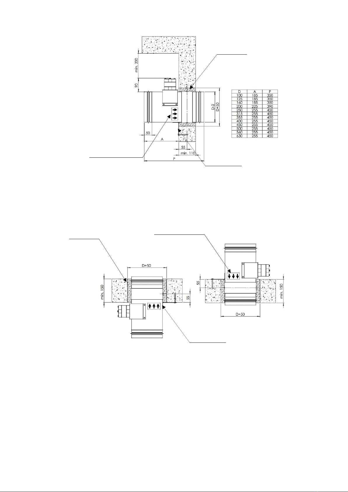
1.1 – OVERALL DIMENSION
To install the damper properly in vertical partition of brick or concrete the required overall dimension is D+50 mm.
1.2 – FIXING AND INSTALLATION
Place the damper axially in the opening. In order to provide partition with fire resistance, it is absolutely necessary
to respect damper installation border line which is clearly marked on the label to be found on the damper casing. In
case of installation in the brick or concrete walls, filling should be made of masonry mortar or non-shrink grout.
NOTE:
- While installing damper it is inadmissible to grime a control mechanism of the damper with mortar, glue or
paints. The control mechanism of the damper has to be absolutely protected until the masonry and painting
works are completed.
- The damper blade has to remain closed during installation and until mortar is hardened. The damper casing
cannot be burdened during installation in partition wall. It can result in deformation of the casing and damage of
the damper blade.
- Minimum clearance of 200 mm should be left for service between the nearest element of the building and the
mechanism.
1.3 – INSTALLATION METHOD
CX-5C can be installed in the following vertical and horizontal spaces:
- concrete walls thickness min. 110 mm,
- wall from full bricks thickness min. 110 mm,
- walls from aerated concrete thickness min. 110 mm,
- concrete ceilings thickness min. 150 mm.
1.3.1 – VERTICAL PARTITION
Minimum thickness of concrete, aerated concrete or brick vertical partition is 110 mm. It is recommended to use
optional UM installation brackets to facilitate installation. Installation brackets are delivered flat and have to be
bended before installation of the product.

IMU-BPP-030-C-2017.08.17 - 2/6
CIAT Sp. z o.o. – ul. Langiewicza 62 – 95-050 Konstantynów Łódzki – POLAND
tel.: (48) 91 432 35 20 – fax: (48) 91 432 35 36 – e-mail: [email protected] – www.gryfit.com
1.3.2 – HORIZONTAL PARTITION
Minimum thickness of concrete ceilings horizontal partition is 150 mm. It is compulsory to use UM installation
brackets. Installation brackets are delivered flat and have to be bended before installation of the product.
1.4 – CONNECTION TO VENTILATION DUCT
During the installation, the damper casing cannot be damaged, in particular, can not take place deformation or
ovalisation. When the damper is connected to the ventilation duct, it is necessary to carry out a test of closing and
opening.
NOTE: Connection of the damper to ventilation or air-conditioning duct has to be done coaxially in order to avoid
knocking the damper blade against the duct’s walls during rotation. This is the necessary condition for the
appropriate working of the damper. The damper should be installed firmly. Mechanical tightening and free
vibrations of ventilation system cannot be transferred onto the damper casing.
1.5 – ELECTRICAL CONNECTION
Connect power supply cable and microswitches cables according to the table and electrical wiring diagram. Perform
the test of power connections.
Label indictaing the border
line of damper installation
Masonry mortar
Installation bracekts
Label indictaing the border
line of damper installation
Masonry mortar
Installation bracekts

IMU-BPP-030-C-2017.08.17 - 3/6
CIAT Sp. z o.o. – ul. Langiewicza 62 – 95-050 Konstantynów Łódzki – POLAND
tel.: (48) 91 432 35 20 – fax: (48) 91 432 35 36 – e-mail: [email protected] – www.gryfit.com
1.5.1 – CX-5C SMOKE CONTROL DAMPER with electromagnet and FDG-8 actuator
1.5.2 –CX-5C SMOKE CONTROL DAMPER with electromagnet, FDG-8 actuator and EMS
1.5.3 – CX-5C SMOKE CONTROL DAMPER with SDG actuator

IMU-BPP-030-C-2017.08.17 - 4/6
CIAT Sp. z o.o. – ul. Langiewicza 62 – 95-050 Konstantynów Łódzki – POLAND
tel.: (48) 91 432 35 20 – fax: (48) 91 432 35 36 – e-mail: [email protected] – www.gryfit.com
1.5.4 – CX-5C SMOKE CONTROL DAMPER with SDG actuator and EMS
1.6 – ELECTROMAGNETS AND ACTUATORS CHARACTERISTICS
E
LECTROMAGNET CHARACTERISTICS
Supply voltage 24 or 48V impulse 230 V AC impulse
Power input 3,5 W 5,5 VA
2 – USAGE INSTRUCTION
2.1 – REMOTE CLOSING AND OPENING OF CX-5C SMOKE CONTROL DAMPER
2.1.1 – CX-5C WITH ELECTROMAGNET AND FDG-8 ACTUATOR OR WITH OPTIONAL EMS MODULE
To close smoke control damper CX-5C make sure the electromagnet is de-energised and apply voltage to the
actuator. The damper will close in less then 71s. Once it is closed remove the voltage supply from the actuator.
To open smoke control damper CX-5C apply impulse to the electromagnet (recommended from 1s up to 3s), which
will trigger the mechanism and close the damper within not longer than 30s. Once the mechanism was triggered it is
necessary to fully close the damper in order to re-arm the mechanism.
ACTUATOR CHARACTERISTICS
Actuator type FDG-8-24 FDG-8-230 SDG-15-24 SDG-15-230
Supply voltage 24 V AC or DC 230 V AC 24 V AC/DC 230 V AC/DC
Power input during
tensioning the spring 3,5 W 9,2 VA 7 W 7 W
Power input during
stand-by 0,5 W 6,9 VA 1,5 W 1,5 W
Time of movement –
engine 55 - 71 s <30s
Time of movement –
spring 20s N/A N/A
Protection class II III II
Protection level IP 54 IP 54
Sound power level <52 dB(A) <55 dB(A)
Working temperature
range -20 ... +50oC -30 ... +50oC
Tolerance of voltage is –10% + 10%

IMU-BPP-030-C-2017.08.17 - 5/6
CIAT Sp. z o.o. – ul. Langiewicza 62 – 95-050 Konstantynów Łódzki – POLAND
tel.: (48) 91 432 35 20 – fax: (48) 91 432 35 36 – e-mail: [email protected] – www.gryfit.com
2.1.2 – CX-5C WITH SDG ACTUATOR OR WITH OPTIONAL EMS MODULE
To close smoke control damper CX-5C apply voltage at actuator wires marked as 1 and 2. The damper will close
after less then 30s. To open smoke control damper CX-5C apply voltage at actuator wires marked as 1 and 3. The
damper will open after less then 30s.
NOTE:
- If the damper has been exposed to fire, it should be replaced with a new one.
- While returning the damper to the closed position, it is recommended to switch off the smoke extraction system
fans.
3 – MAINTENANCE AND SERVICE
The damper does not required special maintenance. However, it is advisable to control the proper working of the
damper and make a written report once a year. Maintenance and service should be carried out by authorized
personnel who have been trained in maintenance by Manufacturer or its local Distributor.
4 – STORAGE
The damper is delivered in the closed position, with the complete control mechanism installed and blocked by the
mechanical lock (in case of FDG actuator) that has to be removed before commissioning. While installing the
damper on the building site, the industrial safety regulations should be respected and this manual should be
followed in order to avoid damage of the damper.
The dampers should be protected from moisture and mechanical shock or impact. It is forbidden to store more than
two dampers one on top of the other. In case of storage on the ground, the dampers should be put on protective
pads in order to avoid damage or deformation of the casing.
During the transport, the damper should be always in the closed postion and in case of FDG actuator it should be
blocked. To do it, use the hex key in slot (1) and rotate it in the direction indicated by the arrow below the slot until
display under the main indicator (3) of the actuator reaches 90 degrees position i.e. damper in closed position. To
block the actuator in this position, turn the screw (2) using screwdriver in the direction indicated by the arrow below.
Now you can release the hex key.
Label of the FDG-8-230 actuator.
3
2
1

IMU-BPP-030-C-2017.08.17 - 6/6
CIAT Sp. z o.o. – ul. Langiewicza 62 – 95-050 Konstantynów Łódzki – POLAND
tel.: (48) 91 432 35 20 – fax: (48) 91 432 35 36 – e-mail: [email protected] – www.gryfit.com
To unblock the FDG actuator, rotate the hex key with 10° in the direction indicated by the arrow below the socket
and then let the actuator rotate freely until the indicator shows the -5 degrees position – damper in open position.
5 – GUARANTEE
The product is subject to a three-year guarantee from the date of sale, provided that product was checked and
necessary maintenance was carried out by personnel authorized by the Manufacturer at least once in the year and
it is documented by the written report delivered to Manufacturer or its local Distributor without delay after product
check. If this condition was not met, a guarantee period would be limited to one year. Distributor is allowed to
extend guarantee conditions to its own risk.
Warranty does not apply to claims for malfunction resulting from non-compliance with this Installation and Usage
Manual. The Manufacturer is not responsible for the components that are installed outdoors and exposed to
weather conditions.
Distributor is the sole responsible entity for execution of guarantee to customers.
Table of contents
Other Gryfit Fire And Smoke Damper manuals
Popular Fire And Smoke Damper manuals by other brands

System air
System air OCWATERLOO PKIR3G ORIGINAL INSTALLATION, OPERATION AND INSPECTION MANUAL

Rf-t
Rf-t CA2 installation manual

Greenheck
Greenheck MBD-15 Installation, operation and maintenance manual

KNF
KNF FPD 06 Operating and installation instructions

VPro
VPro MA Series instruction manual

Mandik
Mandik SEDM-L manual

Nailor
Nailor 1290F quick start guide

Mandik
Mandik FDMD manual

Mandik
Mandik SEDS-L Technical specifications

Schako
Schako BSK-RPR Installation, mounting and operating instructions

TAKACHIHO
TAKACHIHO FYN-M 1 Series manual

Valmet
Valmet Flowrox Expulse Series Installation, operation and maintenance instructions