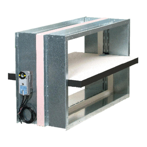
Madel FMC-EIS-120 User manual

1 09/15
•The casing is made of galvanised steel, and joined by
welding.
•The housing is made from galvanized steel. It has a
symmetrical design that allows wall mounting regardless
of air flow.
•The blade is made of ceramic material resistant to high
temperaturesand abrasion.
•These dampers meet the conditions required for the
symbol (S) to cold smoke seal. In case of fire, smoke
poisoning is the leading cause of death.
•The airtightness to the passage of cold smoke is
achieved through a joint between the perimeter of the
housing and the blade. This design, together with the low
thickness of the blade, allow to minimize the pressure
loss..
•For high temperatures,the damper is equipped with an
expanding intumescent seal, forming a paste that prevents
the passage of hot air and smoke from one side of the
damper to another.
•A rubber sealing ring at both ends of the casing ensures
an airtightness between the damper and the ducts.
•The operating devices of the dampers is automatic
shooting by means of a thermal fuse calibrated at 72 °C to
activate the closure when reaches that temperature. Reset
is manual except for motorized dampers.
•The fire dampers FMC-EIS-120 work as a separator
between two sectors of fire and ensure the same fire
resistance that the structural elements of
compartmentalisation,which limits the risk of spreading
of fire by interior of the building.
•FMC-EIS-120 fire dampers are according with the
following standards:
FMC-EIS-120 fire dampers EIS-120
EN 15650:2010
M A
D
E
L
â
European Test Standard, EN 1366-2
(Fire resistance tests for service installations –
Part 2: Fire dampers)
European Classification Standard, EN 13501-3
(Fire classification of construction products and building
elements –
Part 3: Classification using data from fire resistance tests on
products and elements used in building service installations:
fire resisting ducts and fire dampers)
European Standard for CE Marking, EN 15650
(Ventilation for buildings. Fire dampers)
European Test Standard, EN 60529:1991
(Degrees of protection provided by enclosures (IP Code))
European Test Standard EN 1751
(Ventilation for buildings –
Air terminal devices –
Aerodynamic testing of dampers and valves)
International Test Standard ISO 10294-4
(Fire resistance tests –Fire dampers for air distribution systems
Part 4: Test of thermal release mechanism)

2
M A
D
E
L
â
09/15
DECLARATION OF PERFORMANCE
V15-09
Fire damper “FMC-EIS-120”
Madel Air Technical Diffusion S.A,
C/ Pont de les Bruixes P-5, P.I. La Gavarra, 08540 CENTELLES (Barcelona)
To prevent fire and reduce smoke spreadingfrom onefire compartment to
another throughthe air ductworksystem which maypenetrate fire separating
vertical compartments, according to StandardEN 15650:2010(annex ZA.1).
System 1, according to Construction Products Regulation nº305/2011
APPLUS - 0370
Performed tasks:
- Determination of the product type on the basis of type testing (including
sampling), type calculation, tabulated values or descriptive documentationof
the
product;
- Initialinspection of the manufacturing plantand offactory production control;
- Continuous surveillance, assessment andevaluation of factory production
control.
System 1
Certification number: 0370 –CPR –3178
Test report:
15/10323-820
15/10323-819
15/10702-2171
6. Performances (EN 15650 :2010):
Performances
Dimensions Type Wall Type of
installation Mechanism
orientation Class
Rigid wall Reinforced
concrete
≥110 mm Built-in 0-360º EI 120 (vei↔o) S (500Pa)
Rigid wall Brick wall
≥110 mm Built-in 0-360º EI 120 (vei↔o) S (500Pa)
Rigid floor Reinforced
concrete
≥150 mm Built-in 0-360º EI 120 (hoi↔o) S (500Pa)
Sensing element load bearing capacity
Sensing element response temperature
Closure time
50 cycles
…- /MA/ - 300 cycles
…- /M7F…V/ - 10.200 cycles
Sensing element response temperature and load bearing capacity
Opening and Closing cycle
1. Product and identificationname:
Ø100 - 315 mm
Essential characteristics
Cycling (opening and closing) on fire test.
Cycling (opening and closing) according to Standard for CE Marking
5.Certificationbody:
DECLARATION OF PERFORMANCE (Nº 0370-CPR-2178)
Approved
Approved
Approved
Joan Arcarons Alibés
(Technical Director)
Durability of operational reliability according to 15650:
7. The performances of the product identified inpoint1, are inline withthe declared performance in point 6.
This declarationofperformance is issued under the responsibility ofthe
manufacturer listed inpoint 2.
Signed for and on behalfof the manufacturer:
Centelles,09/09/2015
Nominal activation conditions/ sensitivity:
Response delay according to EN 1366-2: Approved
Durability of response delay according to EN1366-2:
4. Assessment of conformitysystem:
Operational reliability according to EN 1366-2
3.Uses to:
2. Name and address of manufacturer:

3
M A
D
E
L
â
PARTS
09/15
FMC-EIS-120 Circular damper with direct connectionto the ducts.
…-MA Manual resetting damper. Is not necessary to open the box device.
…-M7F…Damper operated by an actuator with switch off device at 24 or 230V.
CLASSIFICATION
DIMENSIONS
FMC-EIS-120-M7F…V
Ø
35
H1
65
155
236
Ø
35
H1
70
163
345
345
177
177
100
FMC-EIS-120-MA
-
125
Dn
100
150
160
200
250
300
(mm) Ø
(mm)
98
123
148
158
198
248
298
H1
(mm)
315 313
-
-
-
-
6
31
38
-
125
Dn
100
150
160
200
250
300
(mm) Ø
(mm)
98
123
148
158
198
248
298
H1
(mm)
315 313
-
-
-
-
6
31
38
1. Casing
2. Rubber sealing ring
3. Blade
4. Airtightness seal
5. Cold bridging
6. Manual device /MA/
7. Position indicator
8. Test button
9. Thermal fuse 72ºC
1. Casing
2. Rubber sealing ring
3. Blade
4. Airtightness seal
5. Cold bridging
6. Actuator /M7F…V/
7. Position indicator
8. Test switch
9. Thermoelectrical fuse 72ºC
FMC-EIS-120-MA FMC-EIS-120-M7F…V
1
2
6
7
3
4
5
89
1
2
3
4
5
9
8
7
6

4
M A
D
E
L
â
09/15
OPERATING DEVICES
…-/MA/ Manual resetting damper. Automatic shooting by
means of a thermal fuse calibrated at 72 °C.
Standard:
- Thermal fuse 72ºC
- Manual test button
- Manual resetting
- Position indicator
- IP42 protection
Optional:
…- /PIFR/ Closed switches device
1. Plastic command cover
2. Screws for cover attachment
3. Manual test button
4. Position indicator
5. Manual resetting axe.
6. Thermal fuse 72ºC
…- /M7F…V/ Damper operatedby remote control by means
of an actuator with switch off device at 24 or
230V or a thermal fuse calibrated at 72 °C.
Standard: - Internal and external thermoelectrical
fuse 72ºC
- Automaticresetting
- Automaticclosing by fuse 72ºC
- Remote closing by interruption of power
supply
- Manual test switch
- LED status fusible indicator
- Position damper indicator
- Closed switches
- IP54 Protection 1. Actuator
2. Position damper indicator
3. Manual resetting
4. Manual lock
5. Plug closed switches cable
6. Thermoelectrical fuse cable
7. Power supply cable
8. Thermoelectrical fuse 72ºC
9. Manual test switch
10. LED status fusible indicator
1
2
23
4
5
6
fig. MA
2
1
8
4
3
5
7
6
10
9
fig. M7F…V
fig. PIFR
90s / 15s7Nm
CC 24V/ 48V
CA 24V
M7F24V
90s / 15s7NmCA 230VM7F230V
Time to
Open / Close
Voltage
90s / 15s
3.5W
7Nm
CC 24V/ 48V
CA 24V
M7F24V
90s / 15s
4.5W
7NmCA 230VM7F230V
Torque
Reference Consumption

5
M A
D
E
L
â
09/15
MOUNTING PRECAUTIONS
- Fire damper placement in the floor or wall
Beginning and direction of wall/
floor Placement in wall/ floor Device position
•Wall
•Floor
•Device position
0 - 360º
- The minimum distance between fire dampers
and construction elements will be 75mm.
-The minimum distance between fire dampers will be
200mm.
200
75
200
-Distribution between fire dampers and construction elements:

INSTALLATION AND COMMISSIONING
6
M A
D
E
L
â
09/15
1. DAMPER RECEPTION
Unpack the damper and visually check that has not been damaged during transport.
Do a test at the damper (open / close) to verify that it works correctly .
3. PLACEMENT IN THE CONSTRUCTION SUPPORT
2. WALL OPENING
A. CONSTRUCTION SUPPORT
Place the damper next the construction support
indicated line which is painted on the label. The
arrows show the constructionsupport direction.
B. TEST MEASUREMENTS
After placing the damper in the correct position
(A ) we measure two perpendicular diagonals of
the front and make sure they are equal. Now you
can lock the damper.
[ES] FIJACIÓN: INICIO DE MURO
[GB] FIXING: WALL SITUATION
[FR] FIXATION: DÉBUT DE MUR
[IT] FISSAGIO: INIZIO DEL MURO
Circular opening
Ønominal + 80mm
Ønominal + 15mm

7
M A
D
E
L
â
INSTALLATION AND COMMISSIONING
09/15
6. ELECTRICAL CONNECTION
4. FIRE DAMPER –CONSTRUCTION SUPPORT ATTACHMENT
5. CONNECTION TO AIR DUCTS
FMC-EIS-120-MA+PIF FMC-EIS-120-M7F...V
1
2
3
1
2
3
CONSTRUCTION SUPPORT
SAND AND CEMENT MORTAR
FMC-EIS-120
•Set the damper filling with sand and cement mortar the space between the damper and the
opening.
•Check that the damper blade is not trapped against the housing.
•Avoid projecting mortar moving parts of damper (blade, actuator, manual device).
•Once dry the damper-to-wall assembly, open and close the damper to
check for proper operation.
•Take precautions to ensure that flow of air to get uniformly to the damper and prevent their
installationin the presence of vibrations.
•The inner dimension of the air ducts can not be smaller than inside dimension of the casing.
•Open and close the damper to check that the blade does not touch the duct.
*SWITCHES NORMALLY
CLOSED CONTACTS
COMNFNO COMNFNO
FC DC
Closed damper
signal
Open damper
signal
CONTACT "FC"
COM
NO NF
B. OPEN DAMPERA. CLOSED DAMPER
CONTACT "DC" CONTACT "FC" CONTACT "DC"
COM COM COM
NO NF NO NF NO NF
-5º
45º
90º
STOP
12
3
Nº
3
4
Nº
S1
S2
S3
S4
S5
S6
(SIEMENS GNA 326.1E, GGA 326.1E)
(SIEMENS GNA 126.1E, GGA 126.1E)
MOTOR 230V CA
MOTOR 24V CA/24...48V CC
Nº
1
2
MEANING COLOR
Switch A Input
Switch B Input
Switch A Normally closed
Switch A Normally open
Switch B Normally closed
Switch B Normally open
grey/ red
grey/ blue
grey/ pink
black/ red
black/ blue
black/ pink
MEANING COLOR
Potential system 24VAC/ 24…48VCC
Zero of the system black
red
blue
brown
COLOR
MEANING
Potentiel 230V
Neutral
1. Connection cable for auxiliary switches
2. Connection cable for thermal fuse
3. Connection cable for power
A. CLOSED DAMPER B. OPEN DAMPER
CONTACT “B”CONTACT “A”CONTACT “B”
•ContactA 5º •ContactB 80º
S1
S2 S3
S4
S5 S6
S1
S2 S3
S4
S5 S6
CONTACT “A”

8
M A
D
E
L
â
09/15
SPECIFICATION TEXT
Supply and mounting of fire damper classed
EIS 120, in accordance to the European
Standard EN 13501-3 and CE Marking
according to European Standard, series
FMC-EIS-120-M7F230V diam….
Operated by means of a servomotor at 230V
M7F230 with closed switches. Circular dampers
made from galvanized steel and non-
combustible board. Thermal fusible link at 72ºC.
An expanding joint together an airtightness joint,
as much prevent the propagation of smoke to
high as to low temperature.
Manufacturer MADEL.

9
M A
D
E
L
â
FMC-EIS-120
09/15
TECHNICAL DATA
FREE AREA FOR THE AIR PASS(m2)
Dpt(Pa)
Ønominal
(mm) Afree
(m2)Qmin
(m3/h) Qmax
(m3/h)
100 0,0045 47 235
125 0,008 76 382
150 0,0125 113 564
160 0,0146 129 646
200 0,0244 207 1034
250 0,0403 329 1645
300 0,0601 480 2398
315 0,0668 530 2651
PRESSURE DROP AND SOUND POWER LEVEL
Pa (Pa)
20
200
2000
2 3 4 5 6 7 8 9 10
3000
100
Ø315
Ø250
Ø200
Ø160
Ø125
Ø100
1000
Q (m3/h)
V(m/s)
0
5
10
15
20
25
30
35
40
45
50
55
60
65
70
2
3
4
5
6
7
8
9
10
DPt (Pa)
70
20
V(m/s)
This manual suits for next models
1
Table of contents
Other Madel Fire And Smoke Damper manuals
Popular Fire And Smoke Damper manuals by other brands

SOLID AIR
SOLID AIR FDC25 Technical manual

Trox Technik
Trox Technik AURASAFE mini TX-CTRL Series Guide

EKOVENT
EKOVENT EKO-SRB1 Installation, operating and maintenance instructions

Ace
Ace FYN-S1 Operating and mounting instructions

HVC
HVC NCA 700 Series manual

Trox Technik
Trox Technik FKR-EU Installation and operating manual