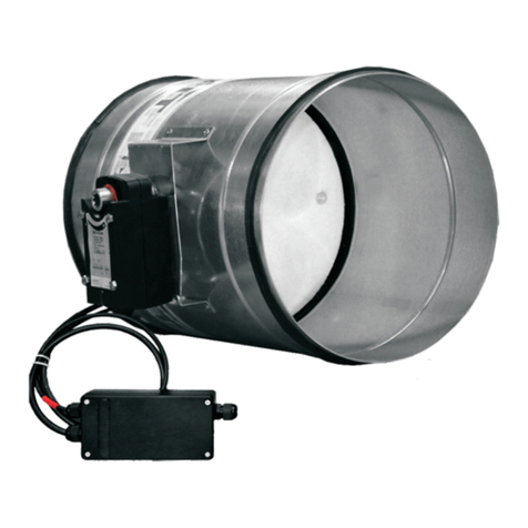
Gryfit LX-5 Setup guide

IMU-BPP-003-J-LX-5-2020.11.05-ENG-1/6
GRYFIT TECHNIK Sp. z o.o. – ul. Łąkowa 11 – 95-050 Konstantynów Łódzki – Polska – tel.: (48) 91 432 35 00 – fax: (48) 91 432 35 36 – e-mail: info@gryfit.com – www.gryfit.com
KRS 0000504565 – NIP 927-193-38-43 – REGON 081202373
INSTALLATION AND USAGE MANUAL
Manufacturer: GRYFIT TECHNIK Sp. z o.o. – ul. Łąkowa 11 – 95-050 Konstantynów Łódzki
LX-5 FIRE DAMPERS
WITH FDG-WT OR BELIMO ACTUATORS
EI (ve – ho – i o) S
CERTIFICATE OF CONSTANCY OF PERFORMANCE
n
o
1488
-
CPR
-
02
78
/
W
1- INSTALLATION
Installation should be carried out by professional who has been trained in GRYFIT components installation.
1.1- OVERALL DIMENSION OF THE INSTALLATION OPENING
To install the damper properly the recommended overall dimension of the installation opening is (L+90) x (H+90) mm if the
damper is installed in the brick, concrete wall or concrete horizontal partition and (L+70) x (H+70) mm if it is installed in the
light-weight wall. Smaller overall dimension of the installation opening is allowed however in that case installation should
be carried with particular care - the clearance between damper body and wall should be entirely filled with the grout or
heat resisting sealant or filler. The minimum overall dimension of the installation opening is determined by the damper
flange size.
1.2- FIXING AND INSTALLATION
Close the damper before installation. Place the damper axially in the installation opening. In order to provide partition walls
with fire resistance, it is absolutely necessary to observe the mortaring border line which is marked on the label on the
damper casing. In case of installation in the brick or concrete walls, facing should be made of masonry mortar or non-
shrink grout. In case of installation in the plaster-cardboard walls, the drawings on the next pages should be followed.
NOTES:
a) Damper mechanism must be always accessible for inspection and maintenance – keep free space of 200 mm
between damper mechanism and nearest building partition or any other obstacle which may restrict the
access to the damper mechanism.
b) It is highly recommended to use the UM optional installation brackets to facilitate installation. Installation
brackets are delivered flat and have to be bended before installation of the product.
c) It is absolutely necessary to respect damper installation mortaring border line which is clearly marked on the
label to be found on the damper casing.
d) While installing it is impermissible to grime a control mechanism of the damper with mortar, sealant, filler,
glue or paints. The control mechanism of the damper has to be protected until the masonry and completion
work is finished.
e) The damper blade has to be closed during installation and until mortar, sealant, filler or glue is hardened. The
damper casing cannot be burdened during installation otherwise it can result in deformation of the casing
and damage of the damper blade.
1.3- INSTALLATION METHOD
The dampers with dimensions up to LxH=1000x1000 can be installed both with their blade axis positioned horizontally and
vertically. As regards the larger dampers it is recommended to install them with their blade axis positioned horizontally, or
to consult with our service center about installation with the blade axis positioned vertically.
1.3.1- APPROVED BUIDLING PARTIONS IN WHICH THE GRYFIT LX-5 DAMPERS CAN BE INSTALLED
The dampers can be installed in the following vertical and horizontal building partitions:
Concrete wall with a thickness not smaller than 125 mm,
Hollow brick walls with a thickness not smaller than 125 mm,
Concrete masonry walls with a thickness not smaller than 125 mm,
Plasterboard walls installed with metal studs framing approved to fire resistance class not less than EI 120 with a
thickness not smaller than 125 mm,
Concrete floor with a thickness not smaller than 150 mm.

IMU-BPP-003-J-LX-5-2020.11.05-ENG-2/6
GRYFIT TECHNIK Sp. z o.o. – ul. Łąkowa 11 – 95-050 Konstantynów Łódzki – Polska – tel.: (48) 91 432 35 00 – fax: (48) 91 432 35 36 – e-mail: info@gryfit.com – www.gryfit.com
KRS 0000504565 – NIP 927-193-38-43 – REGON 081202373
1 - - Building partition
2 - - Masonry mortar
Lr x Hr = L + 90 x H + 90
Detail "A"
1
2
min. 200maks. 75
Label indicating
the fixing line of
the damper
Label indicating
the fixing line of
the damper
1
23 4
1
23 4
1.3.2- BRICK OR CONCRETE WALL
Note: Smaller overall dimension of the installation opening is allowed however in that case installation should be carried with particular care - the
clearance between damper body and wall should be entirely filled with the grout or heat resisting sealant or filler. The minimum overall dimension of
the installation opening is determined by the damper flange size.
1.3.3- PLASTER-CARDBOARD WALL
Schematic light-weight wall shown in the drawing is only an example
Note: Smaller overall dimension of the installation opening is allowed however in that case installation should be carried with particular care - the
clearance between damper body and wall should be entirely filled with the grout or heat resisting sealant or filler. The minimum overall dimension of
the installation opening is determined by the damper flange size.
1.3.4- FLOOR AND CEILING
Installation of the damper in the floor or in the ceiling should be carried out by means of proper elements designed for
installation.
FLOOR CEILING
1. Actuator 3. Mortar filling
2. Steel raw plugs* 4. Steel mounting brackets*

IMU-BPP-003-J-LX-5-2020.11.05-ENG-3/6
GRYFIT TECHNIK Sp. z o.o. – ul. Łąkowa 11 – 95-050 Konstantynów Łódzki – Polska – tel.: (48) 91 432 35 00 – fax: (48) 91 432 35 36 – e-mail: info@gryfit.com – www.gryfit.com
KRS 0000504565 – NIP 927-193-38-43 – REGON 081202373
Note: Smaller overall dimension of the installation opening is allowed however in that case installation should be carried with particular care - the
clearance between damper body and wall should be entirely filled with the grout or heat resisting sealant or filler. The minimum overall dimension of
the installation opening is determined by the damper flange size.
* The number of brackets and steel raw plugs depends on the damper dimensions. Minimum 1 pcs for up to 500 mm side, 2 pcs for up to 1000 mm
side, 3 pcs for over 1000 mm side. Under no circumstances the raw plugs („2”) can disturb the damper facing („3”). In case of installation of the
dampers with large dimensions it is recommended to make shuttering for mortar filling („3”).
1.4- CONNECTION TO VENTILATION DUCT
While installing the damper in the partition, the damper casing cannot be damaged and in particular tightening cannot
occur. When the damper is connected to ventilation duct, the operation test should be carried out.
NOTE: Connection of the damper to ventilation or air-conditioning duct has to be done coaxially in order to avoid
knocking the damper blade against the duct’s walls during rotation. This is the necessary condition for the right
working of the damper.
The damper should be installed firmly, because mechanical tightening and free vibration of ventilation system
cannot be transferred onto the damper casing.
1.5- ELECTRICAL CONNECTION
Connect power cable and microswitches’ cables according to the table and electrical wiring diagram. Run the test of power
connections.
1.5.1 – FDG-WT-5 AND FDG-WT-8 ACTUATORS
ACTUATOR CHARACTERISTICS ACTUATOR TYPE
Actuator type FDG-WT-5-24 FDG-WT-5-230 FDG-WT-8-24 FDG-WT-8-230
Supply voltage 24 V AC lub DC 230 V AC 24 V AC lub DC 230 V AC
Power input during tensioning the
spring 4 W 4 W 3,5 W 9,2 VA
Power input during stand-by 1 W 1 W 0,5 W 6,9 VA
Time of movement – engine <40 s 55 - 71 s
Time of movement – spring <20 s 21 s
Protection class II II
Protection level IP 54 IP 54
Sound power level <45 dB(A) motor,
<65 dB(A) spring
<47 dB(A) motor,
<52 dB(A) spring
Working temperature range -30 ... +50 oC -20 ... +50 oC
Electrical wiring diagram for actuators:
FDG-WT-5-24, FDG-WT-5-230,
FDG-WT-8-24, FDG-WT-8-230.
Electrical wiring diagram for actuators + EMS:
FDG-WT-5-24, FDG-WT-5-230,
FDG-WT-8-24, FDG-WT-8-230.

IMU-BPP-003-J-LX-5-2020.11.05-ENG-4/6
GRYFIT TECHNIK Sp. z o.o. – ul. Łąkowa 11 – 95-050 Konstantynów Łódzki – Polska – tel.: (48) 91 432 35 00 – fax: (48) 91 432 35 36 – e-mail: info@gryfit.com – www.gryfit.com
KRS 0000504565 – NIP 927-193-38-43 – REGON 081202373
Electrical wiring diagram for actuators: BF-24-T,
BF24-T-ST, BF230-T, BLF-24-T, BLF24-T-ST, BLF230-T.
1.5.2 - BELIMO ACTUATORS
BELIMO
Actuator type BF24-T
BF24-T-ST BF230-T BLF24-T
BLF24-T-ST BLF230-T BF24TL-T-ST
Supply voltage 24V
AC/DC
230V
AC
24V
AC/DC
230V
AC
24V
AC/DC
Power input during tensioning the
spring 7W 8W 5W 5W 7W
Power input during stand-by 2W 3W 2,5W 3W 2W
Time of movement - engine 140 s. 140 s. 40 - 75 s. 40 - 75 s. 140 s.
Time of movement - spring 16 s. 16 s. 20 s. 20 s. 16 s.
Protection class III II III II III
Protection level IP54
Sond Power level max. motor 45 dB(A), spring ~ 62 dB(A)
Working temperature - 30C do + 50C

IMU-BPP-003-J-LX-5-2020.11.05-ENG-5/6
GRYFIT TECHNIK Sp. z o.o. – ul. Łąkowa 11 – 95-050 Konstantynów Łódzki – Polska – tel.: (48) 91 432 35 00 – fax: (48) 91 432 35 36 – e-mail: info@gryfit.com – www.gryfit.com
KRS 0000504565 – NIP 927-193-38-43 – REGON 081202373
Electrical wiring diagram for actuators + EMS: BF-24-T,
BF24-T-ST, BF230-T, BLF-24-T, BLF24-T-ST, BLF230-T.
2- USAGE INSTRUCTION
In the stand-by position the damper blade is open.
2.1- OPEN DAMPER – THE STAND-BY POSITION
FDG-WT-5, FDG-WT-8, BLF, BF, actuator types: The damper blade is held in the stand-by position, because electrical
actuator puts constantly the integrated return spring under tension. The damper blade is held in the open position only
when the actuator is powered continuously in 1(-) and 2(+) electrical wires by current supply 24V AC/DC or 230V AC
(depending on the actuator version).
2.2- CLOSURE OF THE DAMPER – TURNING INTO THE SAFETY POSITION
FDG-WT-5, FDG-WT-8, BLF, BF, actuator types: Closure of the blade – turning into the safety position can result from:
activation of the fusible link when the temperature inside the damper casing rises above 70oC, or
pushing the control button on the fusible link (BF and BLF actuators), or
remote control of the damper with the use of current interruption signal (current decay in 1(-) and 2(+) electrical wires
of the actuator and activation of return spring).
2.3- OPENING OF THE DAMPER – RETURN TO THE STAND-BY POSITION
FDG-WT-5, FDG-WT-8, BLF, BF, actuator types: Opening of the blade – turning into the stand-by position can result
from:
current supply in 1(-) and 2(+) electrical wires once again, with continuous voltage 24V AC/DC or 230V AC
(depending on the actuator version), or
manual control, with the use of special spanner (crank) delivered with the actuator.
NOTE:
1. If the damper has been exposed to fire, it should be replaced with a new one.
2. In case of damage or activation of the fusible link (FDG-WT-8, BLF and BF actuator types with fusible links) it
has to be replaced with a new one before re-opening of the damper.
3. While returning the damper to the open position, it is necessary to switch off the fans or air-conditioning and
ventilation central units of ventilation duct which the damper is located in.
3- MAINTENANCE AND SERVICE
The damper does not required special maintenance. However, it is advisable to control the proper working of the damper
and make a written report once a year.
Maintenance and service should be carried out by the service staff of GRYFIT company or by specialists who have been
trained in maintenance of GRYFIT devices.

IMU-BPP-003-J-LX-5-2020.11.05-ENG-6/6
GRYFIT TECHNIK Sp. z o.o. – ul. Łąkowa 11 – 95-050 Konstantynów Łódzki – Polska – tel.: (48) 91 432 35 00 – fax: (48) 91 432 35 36 – e-mail: info@gryfit.com – www.gryfit.com
KRS 0000504565 – NIP 927-193-38-43 – REGON 081202373
4- STORAGE
The damper is delivered in the closed (safety) position, with the complete control mechanism installed. While installing the
damper on the building site, the industrial safety regulations should be observed and this instruction should be followed in
order to avoid damage of the damper.
The dampers should be protected from moisture and mechanical shock or impact. It is forbidden to store more than two
dampers one on top of the other. In case of storage on the ground, the dampers should be put on protective pads in order
to avoid damage or deformation of the casing.
5- GUARANTEE
The product is subject to a three-year guarantee from the date of sale, provided that product was checked and necessary
maintenance was carried out by personnel authorized by the Manufacturer at least once in the year and it is documented
by the written report delivered to Manufacturer or its local Distributor without delay after product check. If this condition
was not met, a guarantee period would be limited to one year. Distributor is allowed to extend guarantee conditions to its
own risk.
Warranty does not apply to claims for malfunction resulting from non-compliance with this Installation and Usage Manual.
The Manufacturer is not responsible for the components that are installed outdoors and exposed to weather conditions.
Distributor is the sole responsible entity for execution of guarantee to customers.
Table of contents
Other Gryfit Fire And Smoke Damper manuals
Popular Fire And Smoke Damper manuals by other brands

Greenheck
Greenheck FD150X Installation, operation and maintenance instructions

Schako
Schako BKA-EN Installation, mounting and operating instructions

Trox Technik
Trox Technik FKR-EU manual

eControls
eControls Comfort365 C365T11 Installation

eControls
eControls R80DV Installer manual

Rf-t
Rf-t CRS60 instruction manual

NuAire
NuAire NRG-IL125 Installation and Maintenance

Greenheck
Greenheck HBS Series Installation, operation and maintenance instructions

Greenheck
Greenheck FD Series Installation instruction supplement

Johnson Controls
Johnson Controls BD-1300 installation instructions

Mandik
Mandik alnor FDMD manual

Kilargo
Kilargo IFD44-LL Series installation instructions