Mandik FDMR Manual

www.mandik.com
MANDÍK, a. s. • Dobříšská 550 • 267 24 Hostomice • Czech Republic • Tel.: +420 311 706 742 • E-Mail: [email protected]
FDMR
Fire damper
Technical Documentation
Installation, Commissioning, Operation, Maintenance and Service Manual
TPM 140/19
Version 2023-06-15

Fire damper - FDMRPage 2 Version 2023-06-15
TPM 140/19
These technical specifications state a row of manufactured sizes and models of fire dampers FDMR
It is valid for production, designing, ordering, delivery, maintenance and operation.
CONTENT
I. GENERAL...........................................................................3
Description....................................................................3
II. DESIGN.............................................................................4
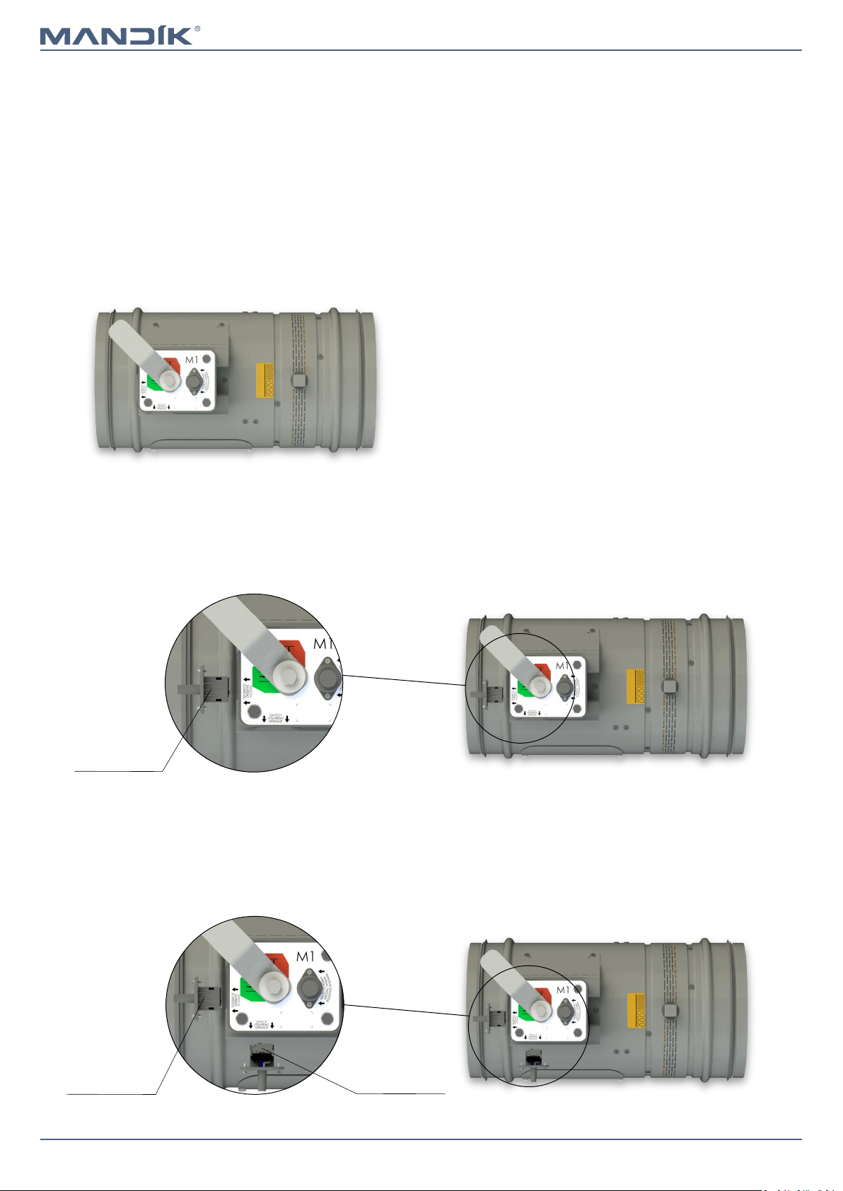
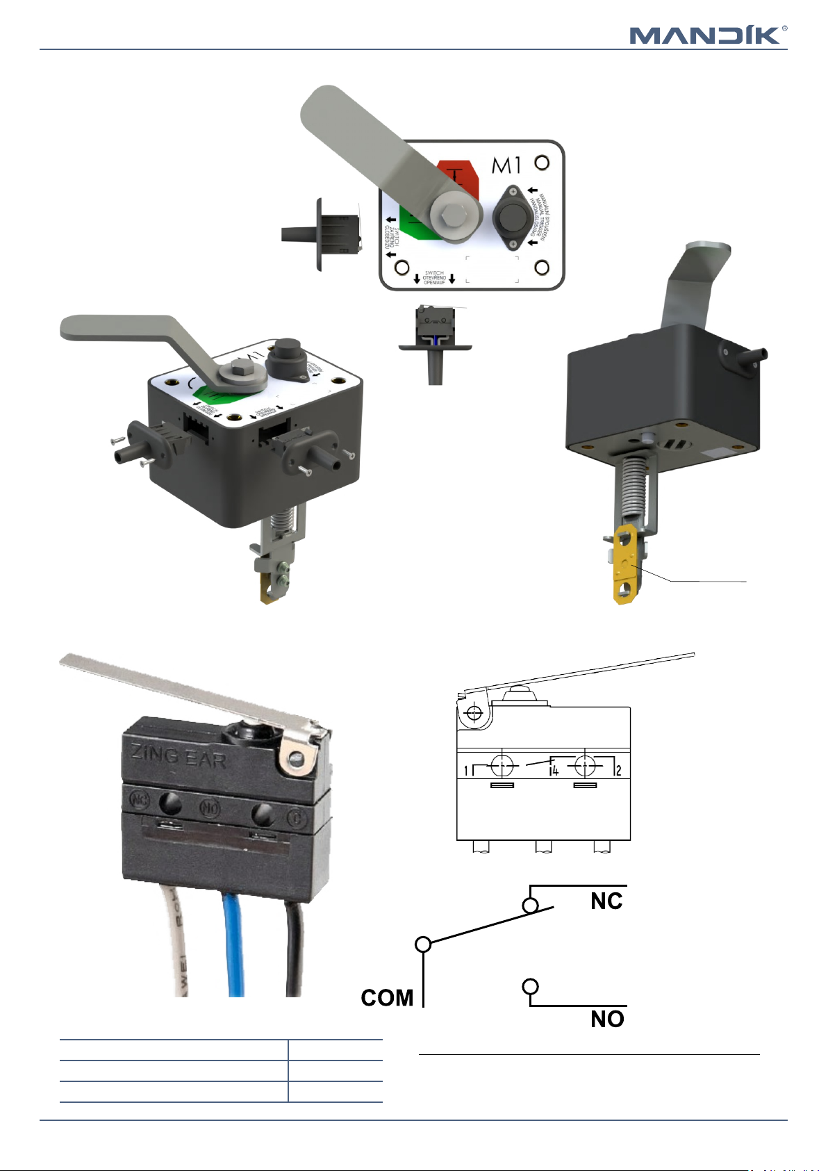
Design with manual control..........................................4
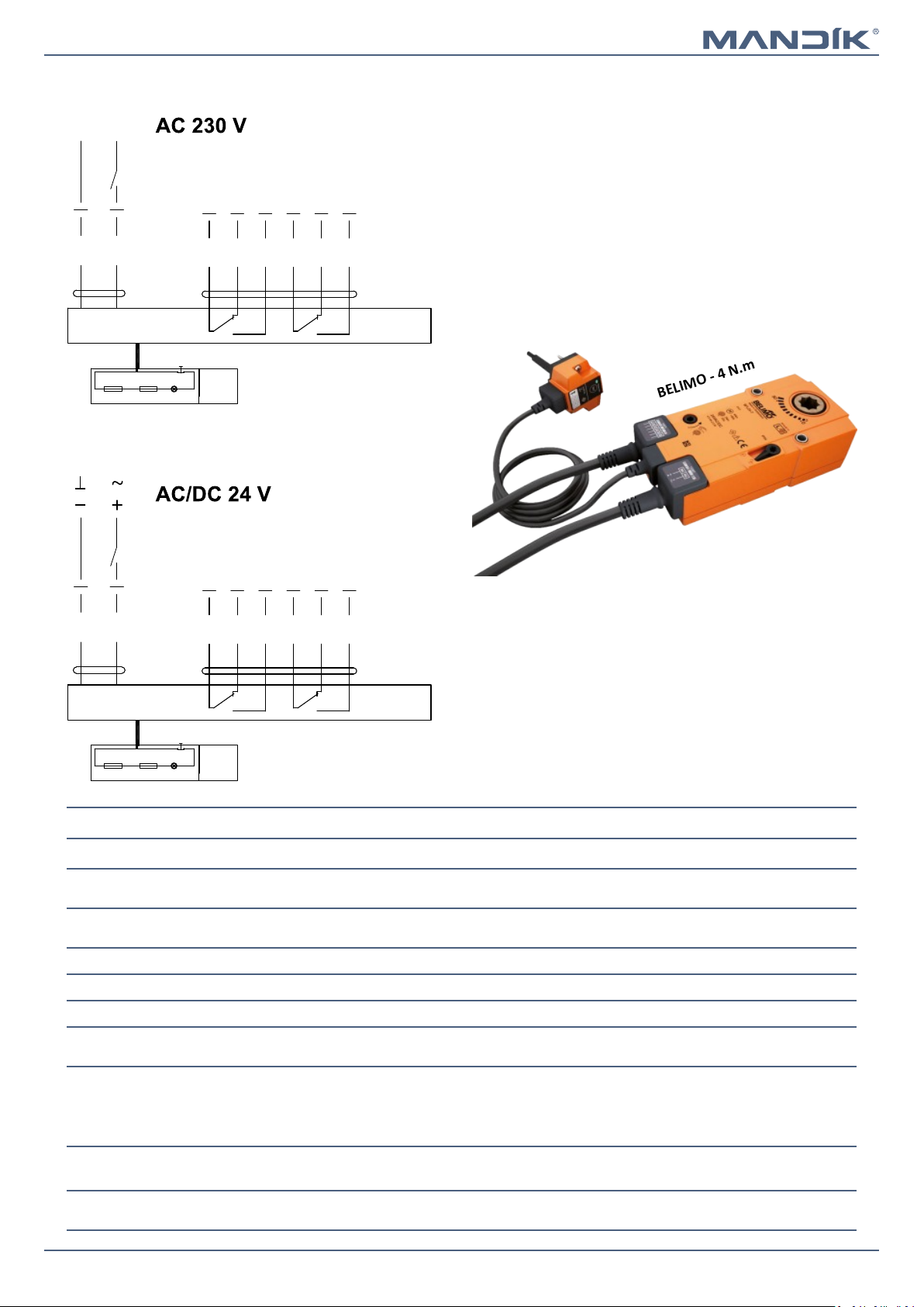
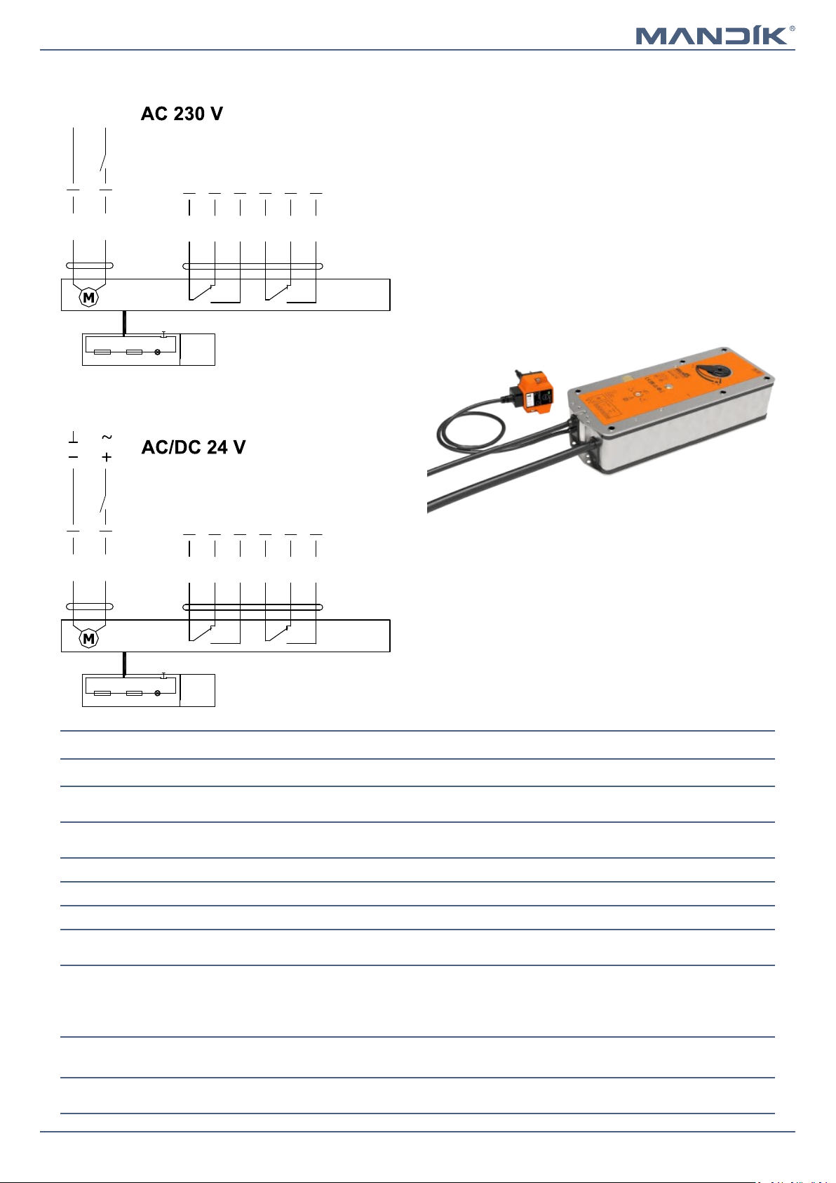
Design with spring return actuator...............................6
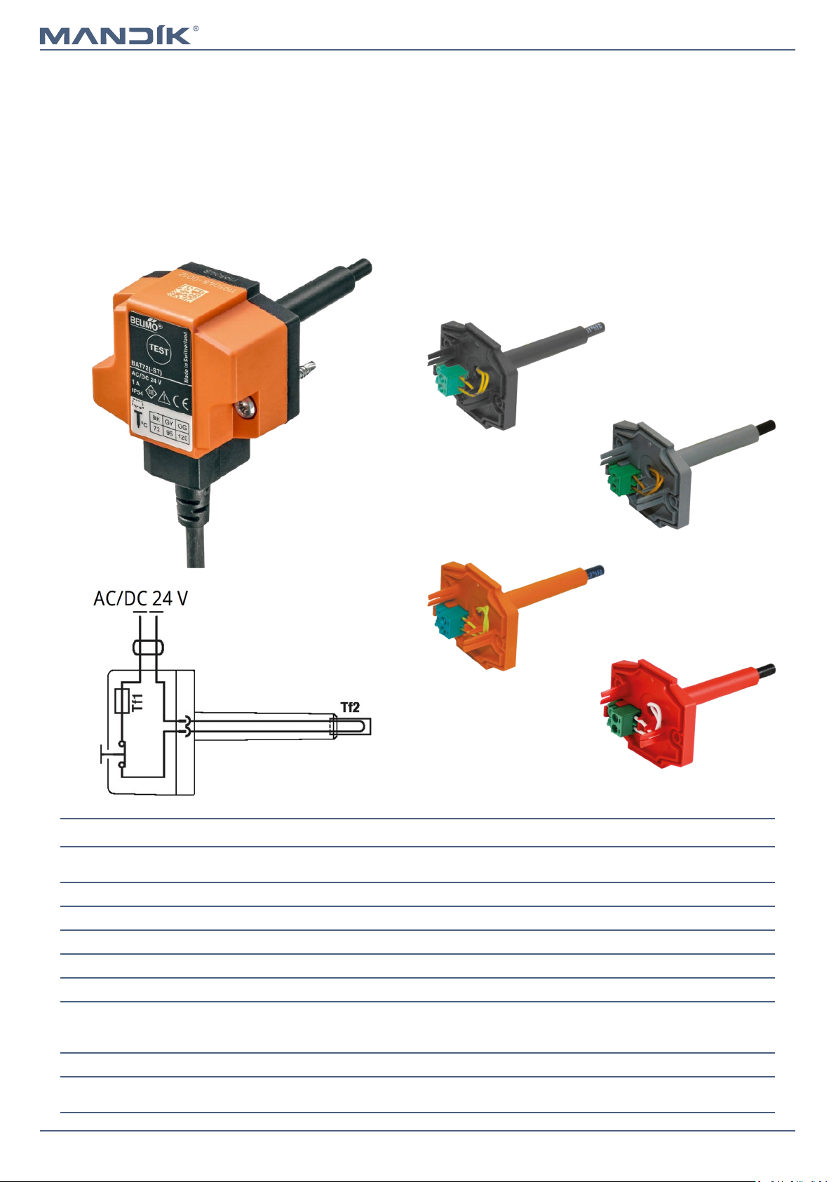
Design with the communication and supply device12
Communication and control device BKS 24-1B and
BKS 24-9A................................................................17
III. DIMENSIONS.................................................................19
Technical parameters.................................................24
IV. INSTALLATION..............................................................25
Placement and installation.........................................25
Statement of installations...........................................27
In solid wall construction.........................................28
Installation outside solid wall constrution..............35
In gypsum wall construction....................................38
Installation outside gypsum wall constrution.........46
Installation in sandwich wall construction..............49
Shaft walls...............................................................50
In solid ceiling construction.....................................53
Installation outside solid ceiling constrution...........57
Installation frames......................................................61
Installation frame R1, R2.........................................62
Installation frame R3, R4.........................................71
Installation frame R5...............................................74
Installation frame R6...............................................81
Installation frame R7...............................................84
V. SUSPENSION SYSTEMS..................................................87
Example of duct connection.......................................90
VI. TECHNICAL DATA..........................................................91
Pressure loss...............................................................91
Noise data...................................................................92
VII. MATERIAL, FINISHING.................................................93
VIII. TRANSPORTATION, STORAGE AND WARRANTY.........94
Logistic terms..............................................................94
Warranty.....................................................................94
IX. ASSEMBLY, ATTENDANCE AND MAINTENANCE...........95
Entry into service and revisions..................................97
X. ORDERING INFORMATIONS...........................................99
Ordering key...............................................................99
Data label..................................................................100

Page 3Version 2023-06-15 Fire damper - FDMR
TPM 140/19
I. GENERAL
Description
Fire dampers are shutters in ducts of air-conditioning devices
that prevent the spread of fire and combustion products from
one fire segment to the other one by means of closing the
duct in the points of fire separating constructions.
Damper blade automatically closes air duct using a closing
spring or a spring return actuator. The closing spring is
actuated by pressing a button on the manual control or by
melting a thermal fuse.
The return spring of the actuator is actuated when a
thermoelectric activation device BAT is activated, when a test
button on BAT is pressed or when power supply of the
actuator is interrupted.
After closing the blade, the damper is sealed with silicon
against smoke penetration. On request by customer, the
damper can be supplied silicon-free. In the closed position,
the damper is also sealed with material which increases its
volume due to increasing temperature and air proofs the air
duct.
Working conditions
■Exact damper function is provided under the following conditions:
■maximum air velocity 12 m/s
■maximum pressure difference 1200 Pa
■the air circulation in the whole damper section must be secured steady over the entire surface.
■Dampers can be installed in position with horizontal or vertical blade axis.
■Dampers can be installed in position with actuating mechanism on top or on the side of the damper.
■Dampers are suitable for systems without abrasive, chemical and adhesive particles.
■Dampers are designed for macroclimatic areas with mild climate according to EN IEC 60 721-3-3 ed.2., class 3K22.
(Environment 3K22 is typically protected place with regulated temperature)
■Temperature in the place of installation is permitted to range from -30°C to +50°C.
Damper characteristics
■CE certified acc. to EN 15650
■Tested in accordance with EN 1366-2
■Classified acc. to EN 13501-3+A1
■External Casing leakage class min. C acc. to EN 1751
■Internal leakage min. class 3 acc. to EN 1751
■Cycling test in class C10000 acc. to EN 15650
■Corrosion resistant acc. to EN 15650
■Certificate of constancy of performance No. 1391-CPR-2021/0145
■Declaration of Perfomance No. PM/FDMR/01/22/1
■Hygienic assessment of fire dampers - Report No. 1.6/pos/19/19b
FDMR with spring return actuator FDMR with manual control

Fire damper - FDMRPage 4 Version 2023-06-15
TPM 140/19
■Design .01 with manual control can be complemented
with a limit switch signaling of the damper blade position
"CLOSED".
■Cable is connected directly to limit switch.
■Limit switch detail → see page 5
Design .11
■Design .01 with manual control can be complemented
with two limit switches signaling of the damper blade
position "CLOSED" and "OPEN".
■Cables are connected directly to limit switches.
■Limit switch detail → see page 5
Design .80
■Design with manual control with a thermal fuse which
actuates the shutting device, after the nominal activation
temperature 72°C has been reached.
■Automatic initiation of the manual control is not activated
if the temperature does not exceed 70°C.
■In case that other activation temperatures are required,
thermal fuses with nominal activation temperature
+104°C or +147°C can be supplied (this requirement must
be specified in the order).
Design .01
ATTENTION:
■Manual controls are produced in five sizes M1 to M5,
difference is only in size of a closing spring, which closes
the fire damper.
■For the size of fire dampers is always assigned the size of
the manual control → see page 24
■It is not recommended to use different size of the manual
control than given by the manufacturer, otherwise there
is a risk of damaging the fire damper.
Design .01
Design .11
Limit switch
“CLOSED”
Design .80
Limit switch
“OPEN”
Limit switch
“CLOSED”
II. DESIGN
Design with manual control

Page 5Version 2023-06-15 Fire damper - FDMR
TPM 140/19
Nominal voltage and maximal current AC 230V / 5A
Class of protection IP 67
Working temperature
-25°C … +120°C
Limit switch G905-300E03W1
This limit switch is possible to connect in two following ways
■CUT-OFF if the arm is moving … connect wire 1+2
■SWITCH-ON if the arm is moving … connect wire 1+4
1(COM) - black wire
2(NC) - gray wire
4(NO) - blue wire
Manual control
Thermal fuse

Fire damper - FDMRPage 6 Version 2023-06-15
TPM 140/19
■The fire dampers are equipped with Belimo spring return
actuators with thermoelectric activation device BAT. The
spring return actuator types are BFL, BFN or BF depending
on the damper size. (Further mentioned as „actuator“).
■After being connected to power supply 230V or AC/DC
24V, the actuator rotates the damper blade to the
operating position "OPEN" and at the same time pre-
stretches its return spring.
■When the actuator is power supplied, the damper blade is
in the position "OPEN" and the return spring is pre-
stretched.
■Time needed for full opening of the damper blade from
the position "CLOSED" to the position "OPEN" is maximum
120 sec. If the actuator power supply is interrupted (due
to loss of supply voltage, or pressing a test button on the
thermoelectric activation device BAT), the actuator
rotates the damper blade to the breakdown position
"CLOSED".
■The time of closing the damper blade from the position
"OPEN" to the position "CLOSED" takes maximum 20 sec.
■In case that the power supply is restored again (the blade
can be in any position), the actuator starts to rotate the
damper blade back to the position "OPEN".
■A thermoelectric activation device BAT, which contains
two thermal fuses Tf1 and Tf2, is an integral part of the
actuator.
■These fuses are activated when temperature +72°C has
been reached (the fuse Tf1 due to temperature outside
the duct and the fuse Tf2 due to temperature inside the
duct). The thermoelectric activation device can also be
equipped with a Tf2 thermal fuse type ZBAT 95/120/140
(must be specified in the order). In this case, the activation
temperature inside the duct is +95°C, +120°C or +140°C
(depending on the type).
■After the thermal fuse Tf1 or Tf2 has been activated, the
power supply is permanently and irreversibly interrupted
and the actuator, by means of the pre-stretched spring,
rotates the damper blade into the breakdown position
"CLOSED".
■Signalisation of damper blade position "OPEN" and
"CLOSE" is provided by two microswitches.
Design .40 and .50
Design .40 and .50
Spring return actuator
Thermoelectric
activation device BAT
Design with spring return actuator

Page 7Version 2023-06-15 Fire damper - FDMR
TPM 140/19
Actuator BELIMO BFL 230-T
Actuator BELIMO BFL 24-T(-ST)
BELIMO - 4 N.m
Actuator BELIMO BFL 230-T(-ST), BFL 24-T(-ST)
Actuator BELIMO - 4 Nm/ 3 Nm Spring BFL 230-T(-ST) BFL 24-T(-ST)
Power voltage AC 230 V
50/60Hz
AC/DC 24 V
50/60Hz
Power consumption - in operation
- in rest position
3,5 W
1,1 W
2,5 W
0,8 W
Dimensioning 6,5 VA (Imax 4 A @ 5 ms) 4 VA (Imax 8,3 A @ 5 ms)
Protection class II III
Degree of protection IP 54
Running time - motor
- spring return
< 60 s
~ 20 s
Ambient temperature
- normal duty
- safety duty
- non-operating temperature
-30°C … +55°C
The safe position will be attained up to max. +75°C
-40°C … +55°C
Connection - supply/control
- auxiliary switch
cable 1 m, 2 x 0,75 mm² (BFL 2xx-T-ST) with 3-pin plug-in connectors
cable 1 m, 6 x 0,75 mm² (BFL 2xx-T-ST) with 6-pin plug-in connectors
Response temperature thermal fuse duct outside temperature +72°C
duct inside temperature +72°C
S2S1 S3 S5S4 S6
2
1
<5° <80°
N L1
BAT
Tf Tf LED
S2S1 S3 S5S4 S6
2
1
<5° <80°
BAT
Tf Tf LED

Fire damper - FDMRPage 8 Version 2023-06-15
TPM 140/19
Actuator BELIMO BFN 24-T(-ST)
BELIMO - 9 N.m
Actuator BELIMO BFN 230-T(-ST), BFN 24-T(-ST)
Actuator BELIMO - 9 Nm/ 7 Nm Spring BFN 230-T(-ST) BFN 24-T(-ST)
Power voltage AC 230 V
50/60Hz
AC/DC 24 V
50/60Hz
Power consumption - in operation
- in rest position
5 W
2,1 W
4 W
1,4 W
Dimensioning 10 VA (Imax 4 A @ 5 ms) 6 VA (Imax 8,3 A @ 5 ms)
Protection class II III
Degree of protection IP 54
Running time - motor
- spring return
< 60 s
~ 20 s
Ambient temperature
- normal duty
- safety duty
- non-operating temperature
-30°C … +55°C
The safe position will be attained up to max. +75°C
-40°C … +55°C
Connection - supply/control
- auxiliary switch
cable 1 m, 2 x 0,75 mm² (BFN 2xx-T-ST) with 3-pin plug-in connectors
cable 1 m, 6 x 0,75 mm² (BFN 2xx-T-ST) with 6-pin plug-in connectors
Response temperature thermal fuse duct outside temperature +72°C
duct inside temperature +72°C
Actuator BELIMO BFN 230-T
S2S1 S3 S5S4 S6
2
1
<5° <80°
N L1
BAT
Tf Tf LED
S2S1 S3 S5S4 S6
2
1
<5° <80°
BAT
Tf Tf LED

Page 9Version 2023-06-15 Fire damper - FDMR
TPM 140/19
Actuator BELIMO BF 230-TN
Actuator BELIMO BF 230-TN(-ST), BF 24-TN(-ST)
Actuator BELIMO - 18 Nm/ 12 Nm Spring BF 230-TN(-ST) BF 24-TN(-ST)
Power voltage AC 230 V
50/60Hz
AC/DC 24 V
50/60Hz
Power consumption - in operation
- in rest position
8,5 W
3 W
7 W
2 W
Dimensioning 11 VA (Imax 8,3 A @ 5 ms) 10 VA (Imax 8,3 A @ 5 ms)
Protection class II III
Degree of protection IP 54
Running time - motor
- spring return
120 s
~ 16 s
Ambient temperature
- normal duty
- safety duty
- non-operating temperature
-30°C … +50°C
The safe position will be attained up to max. +75°C
-40°C … +50°C
Connection - supply/control
- auxiliary switch
cable 1 m, 2 x 0,75 mm² (BF 2xx-TN-ST) with 3-pin plug-in connectors
cable 1 m, 6 x 0,75 mm² (BF 2xx-TN-ST) with 6-pin plug-in connectors
Response temperature thermal fuse duct outside temperature +72°C
duct inside temperature +72°C
BELIMO - 18 N.m
Actuator BELIMO BF 24-TN (-ST)
S2S1 S3 S5S4 S6
2
1
<5° <80°
N L1
BAT
Tf Tf LED
S2S1 S3 S5S4 S6
2
1
<5° <80°
BAT
Tf Tf LED

Fire damper - FDMRPage 10 Version 2023-06-15
TPM 140/19
Thermoelectric activation device BAT 72 (95/120/140)
Power voltage AC/DC 24 V
50/60Hz
Rated current 1 A
AC/DC throughput resistance <1 Ω
Protection class III
Degree of protection IP 54
Probe length 65 mm
Ambient temperature
Storage temperature
Ambient humidity
-30°C … +50°C
-40°C … +50°C
Max. 95% RH, non-condensing
Connection supply Cable 1 m, 2 x 0.5 mm², Betaflam cable heatresistant up to 145°C
Response temperature thermal fuse Duct inside temperature +72 (95/120/140)°C
Duct outside temperature +72 (95/120/140)°C
Thermoelectric activation device BAT
■If the thermal fuse Tf1 is interrupted (due to temperature
outside the duct), it is necessary to replace the spring
return actuator. Thermoelectric activation device BAT is
integral part of the actuator.
■If the thermal fuse Tf2 is interrupted (due to temperature
inside the duct) , only the spare part ZBAT 72
(95/120/140) needs to be replaced (acc.to the activation
temperature).
■When one of the thermal fuses responds, the supply
voltage is interrupted permanently and irreversibly.
■The function (interruption of the supply voltage) can be
checked by pressing the test button.
■Installation is carried out with the pre-assembled, self-
tapping screws.
BELIMO ZBAT 72
Black (BK) = 72°C (standard)
BELIMO ZBAT 95
Grey (GY) = 95°C
BELIMO ZBAT 120
Orange (OG) = 120°C
BELIMO ZBAT 140
Red (RD) = 140°C

Page 11Version 2023-06-15 Fire damper - FDMR
TPM 140/19
■Design .41 or .51 with actuator and smoke detector ORS
142 K. The voltage can be AC 230 V or 24 V DC. Design .41
with voltage AC 230 V is equipped with communication
and supply device BKN 230-24-MOD and with actuator BF
24-TN (BFL 24-T, BFN 24-T).
■The smoke detector is activated when smoke spreads in
air duct system. Deactivation of the smoke detector alarm
status is provided by interruption of supply voltage for
min. 2s.
■Signalisation of damper blade position "OPEN" and
"CLOSE" is provided by two microswitches.
■The smoke detector is not part of the damper in the case
of dampers in diameters from DN 100 mm to DN 200 mm
(including). The smoke detector is supplied separately.
Design .41 and .51
Design .41 with actuator BF 24-TN (BFL, BFN 24-T), with smoke detector ORS 142 K and with supply device BKN 230-24-MOD
(voltage AC 230 V)
1
2
3
4
5
6
7
1
2S2S1 S3 S5S4 S6
2
3
4
5
6
1
BAT
Tf Tf LED
Communication and supply device BKN 230-24-MOD
Nominal voltage AC 230 V 50/60Hz
Power consumption 3 W (operating position)
Dimensioning 14 VA (including actuator)
Protection Class II
Degree of protection IP 40
Ambient temperature
Non-operating temperature
-20°C … +50°C
-40°C … +80°C
Connection - net
- motor
- terminal board
cable 0,9 m with EURO plug type 26
6-pole connector, 3-pole connector
screw terminals for cable 2x1,5 mm²
Design .51 with actuator BF 24-TN (BFL, BFN 24-T), with smoke detector ORS 142 K (voltage 24 V DC)
1
2S2S1 S3 S5S4 S6
24 V DC
2
3
4
5
6
1
BAT
Tf Tf LED

Fire damper - FDMRPage 12 Version 2023-06-15
TPM 140/19
■Design with the communication and supply device BKN
230-24 and actuator BF 24-TN-ST (BFL 24-T-ST, BFN 24-T-
ST). It simplifies electrical wiring and interconnection of
fire dampers. It facilitates on site check and enables
central control and checks of fire dampers by means of a
simple 2-conductor wiring.
■BKN 230-24 functions as a decentralized network device
for supplying the actuator BF 24-TN-ST (BFL 24-T-ST, BFN
24-T-ST) further it transmits the signal informing about
the damper blade position OPERATION and FAILURE
through 2-conductor wiring to the central.
■Control command SWITCHED ON - SWITCHED OFF from
the central through BKN 230-24 goes through the same
wiring to the actuator.
■To simplify the connection, the actuator BF 24-TN-ST (BFL
24-T-ST, BFN 24-T-ST) is equipped with connecting plugs
that are inserted directly to BKN 230-24. BKN 230-24 is
supplied with a conductor and an EURO plug to be
connected to the 230V mains. 2-conductor wiring is
connected to BKN 230-24 by means of terminals 6 and 7.
If the actuator is supposed to be controlled without any
signal from the central, it can be switched on by means of
a bridge between the terminals 3 and 4.
■A green LED on BKN 230-24 is on when voltage is present
in the drive (AC 24V).
■If the test button on BAT is pressed or if the power supply
(e.g. by a signal from ELECTRICAL FIRE SIGNALISATION ) is
disconnected, the damper blade position will be
"FAILURE".
Design .60
Communication and supply device BKN 230-24
Nominal voltage AC 230 V 50/60Hz
Power consumption 3,5 W (operating position)
Dimensioning 11 VA (including actuator)
Protection Class II
Degree of protection IP 40
Ambient temperature
Non-operating temperature
-20°C … +50°C
-40°C … +80°C
Connection - net
- motor
- terminal board
cable 0,9 m with EURO plug type 26
6-pole connector, 3-pole connector
screw terminals for cable 2x1,5 mm²
Communication and supply device BKN 230-24, with actuator BF 24-TN-ST (BFL 24-T-ST, BFN 24-T-ST)
1
2
3
4
5
6
7b
a
1)1)
2)
BAT
1) Bridge has been installed by the manufacturer. If needed, it can be removed ad re-
placed with a thermoelectric activation device. If terminals 1 and 2 are not intercon-
nected, safety function is initiated.
2) Bridge can be used only for starting and without BKS24… !
Two conductor wiring to BKS24
Design with the communication and supply device

Page 13Version 2023-06-15 Fire damper - FDMR
TPM 140/19
Design .61, 61S
■Design with the communication and supply device BKN 230-
24-C-MP, and actuator BF 24-TN-ST (BFL 24-T-ST, BFN 24-T-
ST). It simplifies electrical wiring and interconnection of fire
dampers. Enables central control and checks of fire dampers
by means of a simple 2-conductor wiring and it also allows
connection to the system via MP-BUS communication.
Design 61. can be extended with an optical smoke detector
ORS 142 K (design .61S).
■BKN 230-24-C-MP functions as a decentralized network
device for supplying the actuator BF 24-TN-ST (BFL 24-T-ST,
BFN 24-T-ST) further it transmits the signal informing about
the damper blade position OPERATION and FAILURE through
2-conductor wiring to the central.
■Control command SWITCHED ON - SWITCHED OFF from the
central through BKN 230-24-C-MP goes through the same
wiring to the actuator.
■To simplify the connection, the actuator BF 24-TN-ST (BFL
24-T-ST, BFN 24-T-ST) is equipped with connecting plugs that
are inserted directly to BKN 230-24-C-MP. BKN 230-24-C-MP
is supplied with a conductor and an EURO plug to be
connected to the 230V mains. 2- conductor wiring is
connected to BKN 230-24-C-MP by means of terminals 6 and
7. If the actuator is supposed to be controlled without any
signal from the central, it can be switched on by means of a
bridge between the terminals 3 and 4.
■A green LED on BKN 230-24-C-MP is on when voltage is
present in the drive (AC 24V).
■If the test button on BAT is pressed or if the power supply
(e.g. by a signal from ELECTRICAL FIRE SIGNALISATION ) is
disconnected, the damper blade position will be "FAILURE".
■For design 61S the smoke detector is activated when smoke
spreads in air duct system. Deactivation of the smoke
detector alarm status is provided by interruption of supply
voltage for min. 2s.
■The smoke detector is not part of the damper in the case of
dampers in diameters from DN 100 mm to DN 200 mm
(including). The smoke detector is supplied separately.
Communication and supply device BKN 230-24-C-MP
Nominal voltage AC 230 V 50/60Hz
Power consumption 3,5 W (operating position)
Dimensioning 10 VA (including actuator)
Protection Class II
Degree of protection IP 40
Ambient temperature
Non-operating temperature
-20°C … +50°C
-40°C … +80°C
Connection - net
- motor
- terminal board
cable 0,9 m with EURO plug type 26
6-pole connector, 3-pole connector
screw terminals for cable 2x1,5 mm²
1
2
3
4
5
6
7
2
3
4
5
6
1
12 S2
S1 S3 S5S4 S6
BAT
Tf Tf LED
Design with communication and supply device BKN 230-24-C-MP, with actuator BF 24-TN-ST (BFL 24-T-ST, BFN 24-T-ST) and
smoke detector ORS 142 K
External smoke detector, +24 V, max. 50 mA
External smoke detector, control input
Connection of more BKN devices as slaves
GND
a
b
MP-BUS

Fire damper - FDMRPage 14 Version 2023-06-15
TPM 140/19
Design .63, 63S
■Design with the communication and supply device BKN
230-24-MOD and actuator BF 24-TN-ST (BFL 24-T-ST, BFN
24-T-ST) for communication with control systems using
the Modbus RTU or BACnet MS / TP. Design 63. can be
extended with an optical smoke detector ORS 142 K
(design .63S).
■The wiring of the line is to be carried out in accordance
with applicable RS485 regulations.
■Parameterization of the communication is done using DIL
switches.
■BKN 230-24-MOD can be installed separately, without a
connection to a master control system, in which case the
connection bridge between the terminals 1 and 4 must be
installed.
■If the test button on BAT is pressed or if the power supply
(e.g. by a signal from ELECTRICAL FIRE SIGNALISATION ) is
disconnected, the damper blade position will be
"FAILURE".
■For design 63S the smoke detector is activated when
smoke spreads in air duct system. Deactivation of the
smoke detector alarm status is provided by interruption
of supply voltage for min. 2s.
■The smoke detector is not part of the damper in the case
of dampers in diameters from DN 100 mm to DN 200 mm
(including). The smoke detector is supplied separately.
Communication and supply device BKN 230-24-MOD
Nominal voltage AC 230 V 50/60Hz
Power consumption 3 W (operating position)
Dimensioning 14 VA (including actuator)
Protection Class II
Degree of protection IP 40
Ambient temperature
Non-operating temperature
-20°C … +50°C
-40°C … +80°C
Connection - net
- motor
- terminal board
cable 0,9 m with EURO plug type 26
6-pole connector, 3-pole connector
screw terminals for cable 2x1,5 mm²
Design with communication and supply device BKN 230-24-MOD, with actuator BF 24-TN-ST (BFL 24-T-ST, BFN 24-T-ST) and
smoke detector ORS 142 K
1
2
3
4
5
6
7
2
3
4
5
6
1
12 S2
S1 S3 S5S4 S6
BAT
Tf Tf LED
External smoke detector, +24 V, max. 50 mA
External smoke detector, control input
GND
BKN Direct Control, override control input
D+
D-
GND

Page 15Version 2023-06-15 Fire damper - FDMR
TPM 140/19
■Design with the communication and supply device BKN
230-24MP and actuator BF 24TL-TN-ST for connection to
MP-Bus.
■BKN 230-24MP supplies to the intelligent actuators of fire
dampers BF 24TL-TN-ST decentrally needed power supply.
■In this way can be realize long MP-Bus communications
(up to 800 m).
■Up to 8 Bus nodes can be parallel connected and
controlled by Master device (DDC with interface).
■Device can be equipped with an external smoke detector.
Design .62
Communication and supply device BKN 230-24MP
Nominal voltage AC 230 V 50/60Hz
Power consumption 8 W (including actuator)
Dimensioning 10 VA (including actuator)
Protection Class II
Degree of protection IP 40
Ambient temperature
Non-operating temperature
-30°C … +50°C
-40°C … +80°C
Connection - net
- motor (BF ...-Top)
- net MP
- actuating mechanism (variable)
- Top-Line PC-Tool (via ZIP-RS232)
cable 1 m with EURO plug
4-pole connector
screw terminals 2-pole
3-pole connector
Communication and supply device BKN 230-24MP
PC Tool
17
Ya
24VGND
MP
1) 2)
24V
AC230 V
GND
MP
net MP-Bus additional external conntact,
e.g. fire smoke detector

Fire damper - FDMRPage 16 Version 2023-06-15
TPM 140/19
Optical smoke detector ORS 142 K with the socket 143A
■The smoke detector ORS 142 K is used for early smoke detection
in rooms or inside the ventilation system.
■The sensor operates on the light scatter principle. Inside the
scanning chamber is a light source and a light sensor, in the
normal state the light from the source does not fall on the
senzor. Only when smoke enters the scanning chamber the light
is scattered and falls on the senzor.
■The smoke detector can be connected directly to the actuator
(design .41 and .51) which, in case of smoke detection, passes to
the safety position, or to the BKN communication and supply
device (design .61, .63).
■By early detection of smoke, it can be effectively prevented from
spreading of smoke through the ventilation system. In addition
to smoke detection, the sensor can distinguish and signal slight
and heavy contamination, e.g. the presence of large amounts of
dust.
■The ORS 142 K smoke detector has an alarm memory, i.e. if the
alarm is triggered, the safety relay opens and stays in this state
even if the smoke disappears from the scanning chamber. The
sensor remains in the alarm state until the power supply is
briefly reset.
■On the pin 3, an external device can be connected via RS-Bus
communication to report the status of the sensor.
■Pin 6 has no connection to the detector and is designed as a
load-bearing structure in the base.
ORS 142 K
2
3
4
5
6
1
RS-Bus communication
relay contact
relay contact
Optical smoke detector ORS 142 K with the socket 143A
Operating voltage 18 … 28 V DC
Residual ripple ≤ 200 mV
Power Consumption Socket (without actuator) max. 22 mA
Degree of protection IP 42
Ambient temperature -20°C … +75°C
Aditional temperature senzor +70°C
Connection - net
- motor
- communication and supply device BKN
Cabel 1m, connected to terminals 1, 2 and 4
Actuator connected on the terminals 2 and 5
Cabel 1m, connected to terminals 1, 2, 4 and 5
Socket 143A
Relay contact LED
In operation Green Shines
Slight contamination Green / Yellow Flashes
Heavy contamination Green / Yellow
Flashes
Fault Yellow Shines
Alarm Red Shines
Power Off Off –
4
5
4
5
1 ORS 142 K
2 Socket 143A
3Side cable entries Ø 9mm
4Rear cable entries Ø 9mm
5Fixing hole Ø 4,5 mm
6Fixing hole Ø 3,7 mm
Ø 80
33
33
Ø 80
33
50
59,5

Page 17Version 2023-06-15 Fire damper - FDMR
TPM 140/19
Communication and control device BKS 24-1B
4
7
8
2
10
1
5
9
an insulation
transformer
~
damper position
breakdown
Notice: Relay contacts are drawn
without power
11
b
a
2-conductor wiring
to BKN230-24
Control
on /off
Reset
Test
External buton
optional
be interchanged
6
3
AC
24V
damper position
operation
Reset
Test
open
closed
alarm
failure
Connection through
conection can
not available
, starting with switching AC 24 on or pressing
«Reset/Test» button
possible cause: • short circuit or interruption of 2-conductor wiring
or damper failure (at BKN..) • Power supply AC 230V missing • defective
thermoelectrical starting • smoke detector activated • exceeded operation time
• Fault in system signalled, system check should be
done
Damper (drive) turning into of breakdown position
Damper (drive) in
Damper (drive) turning into of operating position
Damper (drive) in
light diodes contacts Description
Cause/Course
state
open closed alarm
closed
flashing
63
63
67
64
64
63
63
67
switched
closed closed
closed closed
closed closed
closed
closed
closed
closed
closed
closed
closed
closed
open open open
open
open
open
flashing
flashing
• damper blocked
Communication and control device BKS 24-1B
Nominal voltage AC 24 V 50/60Hz
Power consumption 2,5 W (operating position)
Dimensioning 5 VA
Protection Class III
Degree of protection IP 30
Ambient temperature 0°C … +50°C
Connection 11-pole connector ZSO-11, it is not part of BKS24-1B,
ZSO-11 is 11-pole screw terminal 11 x 1,5 mm2
■BKS 24-1B communication and control device is used for control
and checks of fire dampers with the BF 24-TN-ST (BFL 24-T-ST, BFN
24-T-ST) actuator in conjunction with the BKN 230-24 supply and
communication device.
■BKS 24-1B receives information about the situation of the fire
damper through BKN 230-24 supply and communication device
and issues controlling commands.
■The device is intended for building in into the distribution board.
■Light diodes on the front side of the device signalise the operating
situations of the damper and breakdowns of the whole system.
■Potentialless auxiliary contacts enable connection to the master
control system (signaling of the damper position, failure reports,
release of the ventilators etc.).
■While a flashing green LED pilot light signalises damper blade
motion towards the given position, the same pilot light reports
reaching the required position when shining constantly.
■If the damper blade, with respect to the given time, does not
reach the required position, then a red LED pilot light starts to
flash and at the same time, the failure contact is active.
■Once the damper blade reaches the given position, this contact is
deactivated.
■The LED pilot light keeps flashing unless the failure is unblocked
by means of the RESET button.
■Except for reporting failures, other three auxiliary contacts are
available. Contacts showing operating and failure position of the
damper are active when the damper is in the given position.
Function check can be done by pressing and holding the button
"RESET/TEST" for longer time. While holding the button, the
damper blade rotates in the direction of the failure position. Fault
function is indicated by the LED pilot light.
■BKS 24-1B can be connected by means of ZSO-11 11 pole
connector for DIN 35 mm panel.
Communication and control device BKS 24-1B and BKS 24-9A

Fire damper - FDMRPage 18 Version 2023-06-15
TPM 140/19
Function contact K1 Programming K2 Auxiliary Contact
situation state function interconnection state
current failure K2 contact is on if all dampers are open
no failure
K2 contact is on if damper No. 1 is open
K2 contact is on if all dampers are closed
17 18
14 11
15 16
14 12
15 16
14 open
Communication and control device BKS 24-9A
Nominal voltage AC 24 V 50/60Hz
Power consumption 3,5 W
Dimensioning 5,5 VA
Protection Class III
Degree of protection IP 30
Ambient temperature 0°C … +50°C
Connection terminal 2 x 1,5 mm2
■BKS 24-9A communication and control device is used for group
control and checks of 1 to 9 fire dampers with the actuator BF
24-TN-ST (BFL 24-T-ST, BFN 24-T-ST) in connection with the supply
and communication device BKN 230-24.
■Signalisation of the damper position is individual; the damper can
be controlled and tested only as a group.
■BKS 24-9A is intended for use in the distribution board and
displays the operation situations and failure reports of the
connected fire dampers.
■It is possible to signalise functions such as the damper position
and failure reports or to transmit them further to the system by
means of integrated auxiliary switches.
■BKS 24-9A receives signals from BKN 230-24 through the two-
conductor wiring and issues control commands.
Proper damper operation is indicated by two light LED diodes:
■Control ON = position OPERATION
■Control OFF = position FAILURE
■If the fire damper do not reach the given position in time tolerable
for displacing, the appropriate light diode FAILURE starts to flash
and K1 contact is opened (current failure).
■In case that the faulty damper finally reaches its given position, K1
is closed and the failure report light shines (the failure is saved in
memory).
■K2 - the auxiliary contact - is used for signaling of the damper
blade position to the master device.
■Function of this auxiliary contact can be programmed through the
terminal 14.
■Function check can be done in the position OPERATION by means
of pressing the TEST button.
■While the test button is pressed, damper blade is rotating into the
position FAILURE.
■Fault function is indicated by a report "FAILURE".
■Assembly and connection BKS 24-9A can be made by DIN 35 mm
panel. It is connected by two 9-pole plug-in connectors.

Page 19Version 2023-06-15 Fire damper - FDMR
TPM 140/19
SPIRO design with manual control
1 Damper casing
2 Manual control
3 Damper blade
4
Inspection opening cover
5 Sensor sticker
6 Hole for camera
300
50
120
110
400
180
50
ØD-2
120
300
50 50
130
130
110
400
ØD-2
300
50
120
50
110 136
400
39
ØD-2
III. DIMENSIONS

Fire damper - FDMRPage 20 Version 2023-06-15
TPM 140/19
400
130
130
110
ØD
120
400
ØD
110 136
39
120
400
110 180
ØD
120
FLANGE design with manual control
1 Damper casing
2 Manual control
3 Damper blade
4
Inspection opening cover
5 Sensor sticker
6 Hole for camera
Ød
[mm]
Ød1
[mm]
Ød2
[mm]
n
number of holes
in the flange
100 130 10 4
125 155 10 8
160 195 10 8
180 215 10 8
200 235 10 8
225 260 10 8
250 285 10 8
280 315 10 8
300 335 10 8
315 350 10 12
355 390 10 12
400 445 12 12
450 495 12 12
500 545 12 16
560 605 12 16
600 650 12 16
630 680 12 16
710 760 12 20
800 860 12 20
Ød
Ød1
Ød2/n
Other manuals for FDMR
3
Table of contents
Other Mandik Fire And Smoke Damper manuals

Mandik
Mandik FDMQ User manual

Mandik
Mandik SEDS-L User manual

Mandik
Mandik FDMR User manual

Mandik
Mandik FDMB Series User manual

Mandik
Mandik FDMR 60 User manual

Mandik
Mandik SEDM Guide

Mandik
Mandik FDMQ 120 Manual

Mandik
Mandik alnor FDMD User manual

Mandik
Mandik MSD Square Configuration guide

Mandik
Mandik FDMC Series User manual