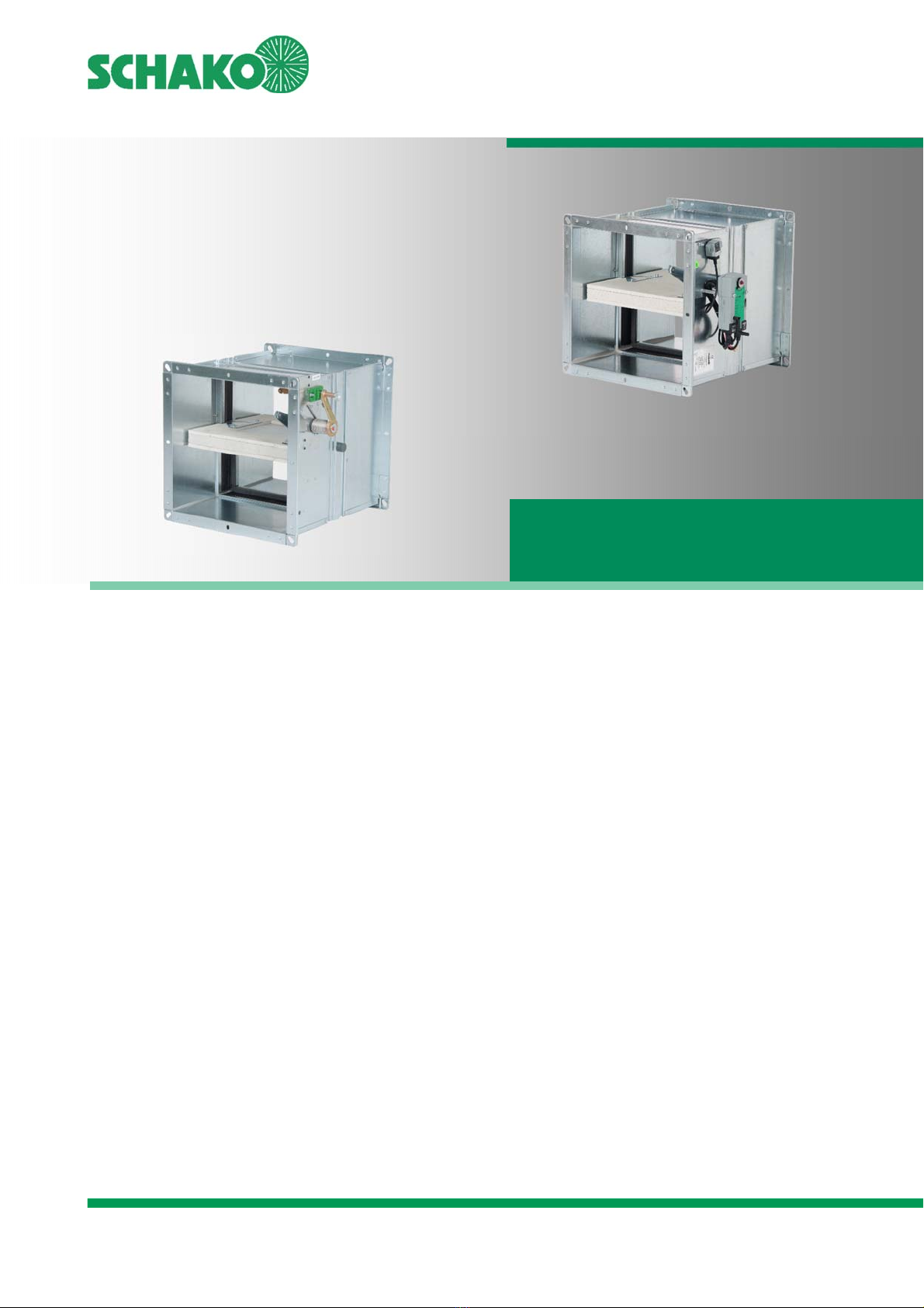
Schako BSK-EN Service manual

SCHAKO | Ferdinand Schad KG Phone +49 (0) 7463-980-0
Steigstraße 25-27 Fax +49 (0) 7463-980-200
D-78600 Kolbingen www.SCHAKO.de | [email protected]
Contents
Description ........................................................................... 2
Models and dimensions ........................................................ 3
Mounting information .......................................................... 5
Installation information ........................................................ 6
Technical data ...................................................................... 7
Accessories ........................................................................... 9
Legend ................................................................................ 14
Specification text ................................................................ 15
Identification label .............................................................. 17
Maintenance or functional test .......................................... 18
Certificate of consistency of performance
1035-CPR-ES054987
Declaration of performance
01-01- DoP-BSK-EN-2014-10-29
BSK-EN
Fire damper
INSTALLATION, MOUNTING AND
OPERATING INSTRUCTIONS

BSK-EN fire damper
INSTALLATION, MOUNTING AND OPERATING INSTRUCTIONS
Description
Construction subject to change
No return possible Version: 2018-11-14 | Page 2
DESCRIPTION
Fire dampers, installed in ventilation ducts (air conditioning
systems), serve for the automatic locking of fire lobbies.
The fire damper BSK-EN complies with EN 15650, EN 13501-3
and EN 1366-2.
BSK-EN is tested according to EN 1366-2 in connection with
Declaration of performance (DoP) no. 01-01- DoP- BSK-EN-
2014-10-29.
It has the certificate of consistency of performance no. 1035-
CPR-ES054987 according to EU-BauPVO.
Category according to EN 13501-3 is EI 120 (v
e
, h
o
i↔o) S.
The national standards and directives must be observed in
connection with the technical documentation Installation,
mounting and operating instructions. For maintenance, ser-
vice, retrofitting, etc., maintenance openings must be provi-
ded on site in suspended ceilings, shaft walls, connected ven-
tilation ducts etc., if necessary. They must be built in in suffi-
cient numbers and sizes and must not impair the functioning
of the fire dampers. The fire dampers must be connected to
the ventilation system by means of ventilation ducts either on
one or on both sides. When connected on one side, finishing
protective gratings made of non-flammable building materials
(EN13501-1) must be provided on the opposite side. The fire
dampers can be connected both on non-combustible and com-
bustible ventilation ducts.
MODELS
• Housing made of galvanised sheet steel, cold and hot
leakage requirements according to EN 1366-2 are met u-
sing circumferential PUR sealings and intumescent seals.
Optionally (at an extra charge) with DD coating (two-com-
ponent paint, PU-based), inside/outside.
• Moulded connecting flanges with centre hole, corner angle
with long hole for simple channel mounting and high sta-
bility.
• Shut-off damper made of fibre-silicate board.
• Thermal release via fusible link 72°C or 98°C.
• Optimum integration in the building control system using
SCHAKO signalling and switching bus system EasyBus (see
technical documentation EasyBus).
• Application: operating pressure max. 1000 Pa at v
stirn
≤ 10
m/s.
• The installation position does not depend on the air flow
direction.
MAINTENANCE INFORMATION
We would like to point out that only suitable cleaning materi-
als may be used to clean the stainless steel version of fire dam-
pers!
ATTENTION
Building systems have to be arranged, installed and maintai-
ned in such a way that they prevent fire and propagation of
fire and smoke (fire propagation) and allow evacuation of per-
sons and animals as well as efficient fire extinguishing work.
Spreading of smoke through the ventilation and air condition-
ing systems can be efficiently prevented only with suitable
electrical triggering device in combination with a smoke detec-
tion system.
Therefore, we recommend to equip fire dampers, for example
with spring return actuators that can be triggered by the
smoke detector.

BSK-EN fire damper
INSTALLATION, MOUNTING AND OPERATING INSTRUCTIONS
Models and dimensions
Construction subject to change
No return possible Version: 2018-11-14 | Page 3
MODELS AND DIMENSIONS
DIMENSIONS
Figure 1: Dimension BSK-EN
FRAME BORE
Figure 2: Frame bores
Available sizes
B
[mm]
H
[mm]
200 200
225 225
250 250
275 275
300 300
325 325
350 350
375 375
400 400
450 450
500 500
550 550
600 600
650 650
700 700
750 750
800 800
900
1000
1100
1200
1300
1400
1500
Table 1: Available sizes
Housing length L= 500 mm.
A
ll width and height dimensions can
be combined.
Release device always on H side.
On request, the width and height di-
mensions are available in steps of 10
mm.
1 Housing
2 Damper blade
3 Hand lever
4 Locking profile
5 Trigger device
6 Fusible link
7 Actuator unit
Corner angle with long
hole
suitable for screws
M8 - M12
The fire damper type BSK-EN is delivered with corner angles for
M8 - M12 screws fitted on the front side.
Connection flange with additional
long holes 9.5 x 16 mm

BSK-EN fire damper
INSTALLATION, MOUNTING AND OPERATING INSTRUCTIONS
Models and dimensions
Construction subject to change
No return possible Version: 2018-11-14 | Page 4
DAMPER LEAF PROJECTING ENDS
Figure 3: Damper leaf projecting ends
BS: Operating side
NBS Non-operating side
ASG Finishing protective grating
VT Extension part
FS Flexible connecting piece
RS Pipe connecting piece
"a" = 50 mm: Minimum distance between the front
edge of the open damper leaf and the fi-
nishing protective grating (ASG), flexible
connecting piece (FS) or pipe connecting
piece (RS).
H [mm] Operating side (BS)
Non-operating side (NBS) [mm]
200 160
x
225 148
250 135
275 123
300 110
325 98
350 85
375 73
400 60
(1)
450 35
(2)
500 10
(2)
550 15
(2)
x1
600 40
(2)
650 65
(2)
700 90
(2)
750 115
(2)
800 140
(2)
T
able 2: Damper leaf projecting ends
(1)
Extension part (VT) on the operating side (BS) necessary
(2)
Extension part (VT) on both sides necessary

BSK-EN fire damper
INSTALLATION, MOUNTING AND OPERATING INSTRUCTIONS
Mounting information
Construction subject to change
No return possible Version: 2018-11-14 | Page 5
MOUNTING INFORMATION
INSTALLATION IN SOLID WALLS
• Installation in solid walls (shaft walls, shafts, ducts and fire
walls) made of, for example concrete, masonry according
to EN 1996 or DIN 1053; solid plaster board walls according
to EN 12859 or DIN 18163; apparent density ≥ 450 kg/m³
and wall thickness W ≥ 150 mm.
• Installation with horizontal damper leaf.
• Circumferential gaps "s" must be filled completely with
mortar of categories M2.5 to M15 according to EN 998-2,
NM II to III DIN V 18580 (previously: MG II to III according
to DIN 1053) or fire protection mortar of the correspon-
ding grade or with concrete suitable for the wall type. The
minimum gap size s
min
is 50 mm. If the fire damper is in-
stalled during the construction of the wall, the gaps "s" can
be omitted. The mortar bed depth has to be designed ac-
cording to the minimum wall thickness and may not be less
than this thickness.
• The distance between the fire dampers must be min. 200
mm.
• Distance to the bearing adjacent components (wall / solid
ceiling) is minimum 75 mm.
INSTALLATION IN SOLID CEILINGS
• Installation in solid ceilings, for example made of concrete,
foam mortar; apparent density ≥ 500 kg/m³ and ceiling
thickness D ≥ 150 mm.
• Installation with full mortar lining (circumferential gaps "s"
must be filled completely with mortar of category M15 ac-
cording to EN 998-2, NM II DIN V 18580 (previously: MG III
according to DIN 1053) or fire protection mortar of the cor-
responding grade. The minimum gap size smin is 50 mm. If
the fire damper is installed during the construction of the
ceiling, the gaps "s" can be omitted. The mortar bed depth
has to be designed according to the minimum ceiling thick-
ness and may not be less than this thickness.
• The distance between the fire dampers must be min. 200
mm.
• Distance to the bearing adjacent components (wall) is mi-
nimum 75 mm.
Installation in solid wall
Installation in solid ceilings
Figure 4: Installation in solid walls and ceilings
CONNECTION OF VENTILATION DUCTS
The fire dampers must be connected to the ventilation ducts
of the ventilation system either on one or on both sides. For
one-sided connections, finishing protective grating made of
non-combustible material (EN 13501-1) must be provided on
the respective opposite sides. The fire dampers can be
connected both to non-combustible and combustible
ventilation ducts.
The local regulations or national standards on ventilation
systems (in Germany e.g. LüAR) apply.
No inadmissible forces may affect the fire damper and space-
enclosing components especially in case of fire and impair
their fire resistance time. The required expansion joints
(flexible connecting pieces) must be designed as flammable,
elastic connecting pieces made of at least standard
inflammable materials (EN 13501-1) and installed between the
fire damper and ventilation duct. Flexible part of the
connecting piece (polyester fabric) must have the minimum
length of l
min
= 100 mm in the mounted state, this gives a
mounting dimension of approx. L = 160 mm. As an alternative,
instead of installing flexible connecting pieces, flexible
ventilation ducts made of aluminium can be connected.
Ventilation ducts must be suspended separately.

BSK-EN fire damper
INSTALLATION, MOUNTING AND OPERATING INSTRUCTIONS
Mounting information | Installation information
Construction subject to change
No return possible Version: 2018-11-14 | Page 6
WITH VENTILATION DUCT ARRANGED ON ONE
SIDE AND FINISHING PROTECTIVE GRATING
Figure 5: Connection example of a ventilation duct arranged on one
side and a finishing protective grating
ON BOTH SIDES WITH VENTILATION DUCTS
Figure 6: Connection example of ventilation ducts on both sides
INSTALLATION INFORMATION
MINIMUM DISTANCES
The specified dimensions should be considered as installation
recommendation for BSK-EN and can deviate depending on
the location. The fire damper must be installed to ensure fire
protection according to the technical documentation Installa-
tion, mounting and operating instructions. Inspection ope-
nings are not available, therefore, they must be created in the
direct vicinity in the connected ventilation ducts. Inspection o-
penings are not available, therefore, they must be created in
the direct vicinity in the connected ventilation ducts. Inspec-
tion openings must be freely accessible, ensure this especially
when installing minimum 2 fire dampers next to each other or
below each other or when installing them in the direct vicinity
of bearing adjacent components.
Minimum distances
1.)
1.) Minimum distances recommended by SCHAKO for better access
during subsequent maintenance.
Figure 7: Minimum distances to adjacent components and BSK-EN to
each other
BSK-EN: Fire damper BSK-EN
ASG Finishing protective grating type ASG
1.)
VT Extension part type VT
FS Flexible connecting piece type FS
2.)
LL Ventilation duct
1.)
made of non-combustible building materials
(EN 13501-1)
2.)
min. standard flammable according to EN
13501-1
a= 50 mm: Minimum distance between the front edge of
the open damper leaf and the finishing protec-
tive grating (ASG), flexible connecting piece (FS)
or pipe connecting piece (RS).

BSK-EN fire damper
INSTALLATION, MOUNTING AND OPERATING INSTRUCTIONS
Technical data
Construction subject to change
No return possible Version: 2018-11-14 | Page 7
TECHNICAL DATA
PRESSURE LOSS AND NOISE LEVEL
Flow generated noise, damper width B = 600 mm
Diagram 1: Damper width B=600 mm
Flow generated noise L
WA
[dB(A)] Radiated noise L
WA Abst
[dB(A)] Pressure loss Δp[Pa]
Without
finishing
protective gra-
ting
With finishing
protective grating
(ASG)
Without
finishing
protective grating
With finishing
protective grating
(ASG)
Without
finishing
protective
grating
With finishing
protective grating
(ASG)
B
[mm]
L
WA1
[dB(A)] =
L
WA
[dB(A)] + KF
1
L
WA2
[dB(A)] =
L
WA1
[dB(A)] x KF
2
L
WA Abst1
[dB(A)] =
L
WA1
[dB(A)] +KF
3
L
WA1 Abst2
[dB(A)] =
L
WA2
[dB(A)] +KF
3
Δp
1
=
Δp x KF
4
Δp
2
=
Δp
1
x KF
5
200 -3 1.05 -7 2.15 1.66
250 -3 1.07 -7 1.8 1.69
300 -2 1.09 -7 1.55 1.72
350 -2 1.10 -7 1.4 2.85
400 -2 1.11 -8 1.3 2.85
450 -1 1.11 -8 1.2 2.85
500 -1 1.11 -8 1.15 2.85
550 -1 1.11 -8 1.05 2.85
600 0 1.11 -8 1 2.85
650 1 1.11 -9 1 2.85
700 1 1.11 -9 0.95 2.85
750 1 1.11 -9 0.9 2.85
800 1 1.11 -9 0.9 2.85
900 1 1.11 -9 0.85 2.85
1000 2 1.11 -9 0.85 2.85
1100 3 1.11 -9 0.85 2.85
1200 4 1.11 -9 0.85 2.85
1300 4 1.11 -9 0.8 2.85
1400 4 1.11 -9 0.8 2.85
1500 5 1.11 -9 0.8 2.85
Table 3: Correction factor for pressure loss and noise level depending on different widths B [mm], at the same flow rate
Correction values B = 600 mm
with finishing protective grating
L
WA
x 1.11
Δp x 2.85
Radiated noise:
L
WA
- 8 [dB(A)]

BSK-EN fire damper
INSTALLATION, MOUNTING AND OPERATING
INSTRUCTIONS
Accessories |
Construction subject to change
No return possible Version: 2018-11-14 | Page 8
WEIGHTS
L= 500 mm, with manual triggering (added weight for actuators: max. 4 kg)
Weight table [kg]
Width (mm)
200 250 300 350 400 450 500 550 600 650 700 750 800 900 1000 1100 1200 1300 1400 1500
Height (mm)
200 9.5 10.4 11.3 12.2 13.1 14.1 15.0 15.9 16.8 17.7 18.7 19.6 20.5 22.3 24.2 26.0 27.9 29.7 31.5 33.4
250 10.4 11.4 12.4 13.4 14.4 15.3 16.3 17.3 18.3 19.3 20.3 21.3 22.3 24.3 26.3 28.2 30.2 32.2 34.2 36.2
300 11.3 12.4 13.4 14.5 15.5 16.6 17.7 18.7 19.8 20.9 21.9 23.0 24.1 26.2 28.3 30.4 32.6 34.7 36.8 38.9
350 12.2 13.4 14.5 15.6 16.8 17.9 19.0 20.2 21.3 22.4 23.6 24.7 25.8 28.1 30.4 32.6 34.9 37.2 39.4 41.7
400 13.1 14.4 15.5 16.8 18.0 19.2 20.4 21.6 22.8 24.0 25.2 26.4 27.6 30.0 32.4 34.9 37.3 39.7 42.1 44.5
450 14.1 15.3 16.6 17.9 19.2 20.5 21.7 23.0 24.3 25.6 26.8 28.1 29.4 31.9 34.5 37.1 39.6 42.2 44.7 47.3
500 15.0 16.3 17.7 19.0 20.4 21.7 23.1 24.4 25.8 27.1 28.5 29.8 31.2 33.9 36.6 39.3 42.0 44.7 47.3 50.1
550 15.9 17.3 18.7 20.2 21.6 23.0 24.4 25.8 27.3 28.7 30.1 31.5 32.9 35.8 38.6 41.5 44.3 47.2 50.0 52.8
600 16.8 18.3 19.8 21.3 22.8 24.3 25.8 27.3 28.8 30.3 31.7 33.2 34.7 37.7 40.7 43.7 46.7 49.6 52.6 55.6
650 17.7 19.3 20.9 22.4 24.0 25.6 27.1 28.7 30.3 31.8 33.4 34.9 36.5 39.6 42.8 45.9 49.0 52.1 55.3 58.4
700 18.7 20.3 21.9 23.6 25.2 26.8 28.5 30.1 31.7 33.4 35.0 36.7 38.3 41.5 44.8 48.1 51.4 54.6 57.9 61.2
750 19.6 21.3 23.0 24.7 26.4 28.1 29.8 31.5 33.2 34.9 36.7 38.4 40.1 43.5 46.9 50.3 53.7 57.1 60.5 64.0
800 20.5 22.3 24.1 25.8 27.6 29.4 31.2 32.9 34.7 36.5 38.3 40.1 41.8 45.4 49.0 52.5 56.1 59.6 63.2 66.7
Table 4: Weight table [kg]
FREE CROSS-SECTION
Free cross-section [m2]
Width [mm]
200 250 300 350 400 450 500 550 600 650 700 750 800 900 1000 1100 1200 1300 1400 1500
Height (mm)
200 0.018 0.023 0.029 0.034 0.040 0.045 0.051 0.056 0.062 0.067 0.073 0.078 0.084 0.095 0.106 0.117 0.128 0.139 0.150 0.161
250 0.026 0.034 0.042 0.050 0.058 0.066 0.074 0.082 0.090 0.098 0.106 0.114 0.122 0.138 0.154 0.170 0.186 0.202 0.218 0.234
300 0.034 0.044 0.055 0.065 0.076 0.086 0.097 0.107 0.118 0.128 0.139 0.149 0.160 0.181 0.202 0.223 0.244 0.265 0.286 0.307
350 0.042 0.055 0.068 0.081 0.094 0.107 0.120 0.133 0.146 0.159 0.172 0.185 0.198 0.224 0.250 0.276 0.302 0.328 0.354 0.380
400 0.050 0.065 0.081 0.096 0.112 0.127 0.143 0.158 0.174 0.189 0.205 0.220 0.236 0.267 0.298 0.329 0.360 0.391 0.422 0.453
450 0.058 0.076 0.094 0.112 0.130 0.148 0.166 0.184 0.202 0.220 0.238 0.256 0.274 0.310 0.346 0.382 0.418 0.454 0.490 0.526
500 0.066 0.086 0.107 0.127 0.148 0.168 0.189 0.209 0.230 0.250 0.271 0.291 0.312 0.353 0.394 0.435 0.476 0.517 0.558 0.599
550 0.074 0.097 0.120 0.143 0.166 0.189 0.212 0.235 0.258 0.281 0.304 0.327 0.350 0.396 0.442 0.488 0.534 0.580 0.626 0.672
600 0.082 0.107 0.133 0.158 0.184 0.209 0.235 0.260 0.286 0.311 0.337 0.362 0.388 0.439 0.490 0.541 0.592 0.643 0.694 0.745
650 0.090 0.118 0.146 0.174 0.202 0.230 0.258 0.286 0.314 0.342 0.370 0.398 0.426 0.482 0.538 0.594 0.650 0.706 0.762 0.818
700 0.098 0.128 0.159 0.189 0.220 0.250 0.281 0.311 0.342 0.372 0.403 0.433 0.464 0.525 0.586 0.647 0.708 0.769 0.830 0.891
750 0.106 0.139 0.172 0.205 0.238 0.271 0.304 0.337 0.370 0.403 0.436 0.469 0.502 0.568 0.634 0.700 0.766 0.832 0.898 0.964
800 0.114 0.149 0.185 0.220 0.256 0.291 0.327 0.362 0.398 0.433 0.469 0.504 0.540 0.611 0.682 0.753 0.824 0.895 0.966 1.037
Table 5: Free cross-section [m²]

BSK-EN fire damper
INSTALLATION, MOUNTING AND OPERATING INSTRUCTIONS
Accessories
Construction subject to change
No return possible Version: 2018-11-14 | Page 9
ACCESSORIES
Available at an extra charge:
• Model with additional DD coating (solvent-based two-
component paint, PU-based - RAL 7035 / light grey) in-
side/outside.
• Thermal release via fusible link 98°C.
• Electric spring return actuators B10/B11, B20/B21, B30/
B31, B40.
• Signalling and switching bus system type EasyBus.
• Finishing protective grating type ASG
1.)
.
• Extension part type VT
1.)
.
• Pipe connecting piece type RS
1.)
.
1.)
Standard model galvanised sheet steel, powder-coated
(RAL 9010 / pure white) and DD coating (RAL 7035 / light
grey) possible.
LIMIT SWITCH TYPE ES
Electric limit switch for position indicators "OPEN" and/or
"CLOSED". Switching element including one NC and one NO
contact each, 4 connections for M3.5 screw terminals for max.
2 mm². 250 V AC, I
e
6A, IP67 using suitable cable glands M20
(on-site).
ES circuit diagram
Damper positions that can
be displayed:
Type ES 1 Z : "CLOSED"
Type ES 1 A : "OPEN"
Type ES 2 : "OPEN"
and "CLOSED"
Figure 8: Circuit diagram Limit switch type ES
Limit switch type Easy-Eco-Tx
Technical description and documents: see technical documen-
tation signalling and switching bus system EasyBus.

BSK-EN fire damper
INSTALLATION, MOUNTING AND OPERATING INSTRUCTIONS
Accessories
Construction subject to change
No return possible Version: 2018-11-14 | Page 10
ELECTRIC SPRING RETURN ACTUATOR
B10/B11/B20/B21
B10 (BFL24-T-ST SO), B11 (BFL230-T SO)
B20 (BFN24-T-ST SO), B21 (BFN230-T SO)
Connection diagram
B10/B11/B20/B21
Figure 9: Connection diagram B10/B11/B20/B21
ELECTRIC SPRING RETURN ACTUATOR B30/B31
B30 (BF24-T-ST SO), B31 (BF230-T SO)
Connection diagram
B30/B31
Figure 10: Connection diagram B30/B31
ELECTRIC SPRING RETURN ACTUATOR B40
B40 (BF24TL-T-ST SO)
Connection diagram
B40
Figure 11: Connection diagram B40
Electric spring return actuator with thermoelectric release
device BAT or BAE72B-S.
• Release temperature 72°C optional 95°C and 120°C (for
hot-air heating).
• Operating position (damper "OPEN") and tensioning of the
return spring by applying the supply voltage.
• 24V actuators with connectors that can be removed on site
if required.
• Safety position (damper "CLOSED") through spring force
when supply voltage is interrupted or the temperature fu-
ses (ambient temperature or internal duct temperature)
respond. Reaction of the thermal fuses interrupts the
supply voltage permanently.
• Display of the damper end positions is possible by means
of integrated micro switches via potential-free changeover
contacts (S1 – S3 "CLOSED" indicates the closed position;
S4 – S6 "OPEN" indicates the opened position).
• Manual actuation and fixing in any position is possible in
the de-energised state. It is unlocked manually.
• On-site function control is possible by means of the control
key of BAT or BAE72B-S.
• Spare parts: Temperature fuse for temperature inside the
duct 72°C/95°C/120°C (ZBAT72 or ZBAE72 and ZBAT95 or
ZBAE95 and ZBAT120). Exchange takes place by unscre-
wing the two screws of the thermoelectric release device.
Remove the thermoelectric trigger device from the actua-
tor unit. Remove the internal duct temperature fuse from
the thermoelectric release device and replace it with a new
internal duct temperature fuse (ZBAT... or ZBAE...). Screw
the thermoelectric trigger device back onto the actuator
unit. For any other damage, the entire "actuator/thermal
release device" unit must be replaced completely.
Electric spring return actuator with thermoelectric
trigger device BAE72TL.
• Trigger temperature 72°C optionally 95°C (for hot-air hea-
ting).
• Supply voltage 24V AC/DC including connector.
• Connection to LON or Belimo MP bus systems is possible
via communication and power supply units BKN230-24LON
or BKN230-24MP.
Further technical data are available on request.
The safety function is only guaranteed if the
drive has been connected to the supply vol-
tage in accordance with regulations.
Parallel connection of further drives is
possible. Observe performance data.
B10 (BFL24-T-ST SO) or
B20 (BFN24-T-ST SO):
Plug-in version for con-
nection to the communi-
cation and power supply
unit BKN230-24
B30 (BF24-T-ST SO):
Plug-in version for con-
nection to the communi-
cation and power supply
unit BKN230-24
Parallel connection of further drives is
possible. Observe performance data.

BSK-EN fire damper
INSTALLATION, MOUNTING AND OPERATING INSTRUCTIONS
Accessories
Construction subject to change
No return possible Version: 2018-11-14 | Page 11
Motor graduation and damper dimensions
Motor graduation
Table 6: Motor graduation
Damper dimensions
* BSK- EN with B10/B11 approx. 102 mm
* BSK- EN with B20/B21 approx. 106 mm
* BSK- EN with B30/B31 approx. 120 mm
Figure 12: Damper dimensions
200 225 250 275 300 325 350 375 400 450 500 550 600 650 700 750 800 900 1000 1100 1200 1300 1400 1500
200
225
250
275
300
325
350
375
400
450
500
550
600
650
700
750
800
B30 (BF24-T-ST SO) bzw. B31 (BF230-T SO)
Breite (B) [mm]
Höhe (H) [mm]
B10 (BFL24-T-ST SO) bzw. B11 (BFL230-T SO)
B20 (BFN24-T-ST SO) bzw. B21 (BFN230-T SO)

BSK-EN fire damper
INSTALLATION, MOUNTING AND OPERATING INSTRUCTIONS
Accessories
Construction subject to change
No return possible Version: 2018-11-14 | Page 12
Technical data of spring return actuators
24 V actuators B10 (BFL24-T-ST-SO) B20 (BFN24-T-ST-SO) B30 (BF24-T-ST-SO)
Nominal voltage AC/DC 24 V
Rated voltage frequency 50/60 Hz
Functional range AC 19.2...28.8 V/DC 21.6...28.8 V
Power consumption during operation 2.5 W 4 W 7 W
Power consumption in idle position 0.8 W 1.4 W 2 W
Power consumption/dimensioning 4 VA/Imax 8.3 A @ 5 ms 6 VA/Imax 8.3 A @ 5 ms 10 VA/Imax 8.3 A @ 5 ms
Auxiliary switch 2 x EPU
Switching capacity of auxiliary switch 1 mA…3 (0.5 inductive) A, AC 250 V 1 mA…6 (3) A, DC 5 V…AC 250 V
Connection of supply / control Cable 1 m, 2 x 0.75 mm² (halogen-free), with 3-pin connector
Auxiliary switch connection Cable 1 m, 6 x 0.75 mm² (halogen-free), with 6-pin connector
Motor runtime <60 s / 90° < 120 s/90°
Spring return runtime 20s @ -10...55°C / <60s @ -30...-10°C ~ 16 s @ -20°C
Protection class IEC/EN Safety extra low voltage III
Protection class auxiliary switch IEC/EN II protective insulation
Degree of protection IEC/EN IP54
Ambient temperature Normal operation -30 ... 55°C -30 ... 50°C
Storage temperature -40 ... 55°C -40 ... 50°C
Ambient humidity 95% r.H., non-condensing
Table 7: Technical data 24 V actuators
230 V actuators B11 (BFL230-T SO) B21 (BFN230-T SO) B31 (BF230-T SO)
Nominal voltage AC 230 V
Rated voltage frequency 50/60 Hz
Functional range AC 198 ... 264 V
Power consumption during operation 3.5 W 5 W 8.5 W
Power consumption in idle position 1.1 W 2.1 W 3 W
Power consumption/dimensioning 6.5 VA/Imax 4A @ 5 ms 10 VA/Imax 4A @ 5 ms 11 VA/Imax 500 mA @ 5 ms
Auxiliary switch 2 x EPU
Switching capacity of auxiliary switch 1 mA…3 (0.5 inductive) A, AC 250 V 1 mA…3 (0.5 inductive) A, AC 250 V
Connection of supply / control Cable 1 m, 2 x 0.75 mm² (halogen-free)
Auxiliary switch connection Cable 1 m, 6 x 0.75 mm² (halogen-free)
Motor runtime <60 s / 90° < 120 s/90°
Spring return runtime 20s @ -10...55°C / <60s @ -30...-10°C ~ 16 s @ -20°C
Protection class IEC/EN II protective insulation
Protection class auxiliary switch IEC/EN II protective insulation
Degree of protection IEC/EN IP54
Ambient temperature Normal operation -30 ... 55°C -30 ... 50°C
Storage temperature -40 ... 55°C -40 ... 50°C
Ambient humidity 95% r.H., non-condensing
Table 8: Technical data 24 V actuators

BSK-EN fire damper
INSTALLATION, MOUNTING AND OPERATING INSTRUCTIONS
Accessories
Construction subject to change
No return possible Version: 2018-11-14 | Page 13
EXTENSION PART TYPE VT
Figure 13: Extension part type VT
• Extension part made of profiled sheet steel fitted with
connecting flanges.
• Intended use: for large wall/ceiling thicknesses, in order to
maintain a minimum distance a
min
= 50 mm from the open
damper blade when fitting protective finishing grating type
ASG, flexible connecting pieces type FS or connecting pipes
type RS
H
[mm]
L
[mm]
The L dimension depends on the height.
200
180
250
300
350
400
450
500
550
600
650
700
750
800 210
Table 9: Length of the extension part type VT depending on the fire
damper height
FLEXIBLE CONNECTING PIECE TYPE FS
Figure 14: Flexible connecting piece type FS
• Flexible connecting piece consisting of profiled connection
flanges (galvanised sheet steel) with elastic intermediate
piece made of polyester fabric PVC-coated on both sides,
standard flammable according to EN 13501-1, with welded
lip seals (sealing degree C according to EN 13180 / EN
1507; temperature-resistant from -20° to 80°C). Flexible
part of the connecting piece (polyester fabric) must have a
length l
min
of 100 mm when mounted, this gives an instal-
lation dimension of approx. L=160 mm.
• The required equipotential bonding must be carried out
on-site according to the VDE or local regulations. The fire
dampers must not be subject to mechanical stress under
any circumstances.
• Flexible ventilation ducts made of steel or aluminium can
be used instead of the flexible connection pieces.
• Flexible spigot must be installed in the scrapped state. This
may reduce the free cross section. An extension piece may
be necessary.
• For H ≥ 400, observe table 2 page 4.
DUCT CONNECTION SPIGOT TYPE RS
W x H
[mm]
øD
[mm]
200x200 198
250x250 248
400x400 398
450x450 448
500x500 498
600x600 558
650x650 628
750x750 708
800x800 798
Figure 15: Pipe connecting piece type RS
• Pipe connecting pieces with joining plate, galvanised sheet
steel.
• Intended use: connection/transition fire damper to round
ducts.
• Other dimensions on request.
• For H ≥ 400, observe table 2 page 4.
Equipotential bonding
(on site)

BSK-EN fire damper
INSTALLATION, MOUNTING AND OPERATING INSTRUCTIONS
Accessories | Legend
Construction subject to change
No return possible Version: 2018-11-14 | Page 14
SECURITY GRILLE TYPE ASG
Figure 16: Finishing protective grating type ASG
• Wire or punch grid with a mesh size of ≤ 20 mm.
• Intended use: mounting for one-sided connection.
• Minimum distance a
min
= 50 mm from open damper blade
must be considered; if necessary, use extension part type
VT.
• For H≥400, observe table 2 page 4.
LEGEND
V
ZU
[m³/h] [l/s] = Supply air volume
Δp
st
[Pa] = Static pressure
L
WA
[dB(A)] = A-weighted sound power level
v
stirn
[m/s] = Face velocity
ρ[kg/m³]=Density
B [mm] = Width
H [mm] = Height
L
WA1
[dB(A)] = A-weighted sound power level of the
flow-generated noise, adjusted for diffe-
rent values of B [mm]
KF
1
[dB(A)] = Correction factor of sound power le-
vel,,,,, of the flow generated noise,
adjusted for different values of B [mm]
L
WA2
[dB(A)] = A-weighted sound power level of the
flow-generated noise, adjusted for diffe-
rent values of B [mm], in the model with
finishing protective grating (ASG)
KF
2
[dB(A)] = A-weighted sound power level of the
flow-generated noise, adjusted for diffe-
rent values of B [mm], in the model with
finishing protective grating (ASG)
L
WA Abst1
[dB(A)] = A-weighted sound power level of the ra-
diated noise, adjusted for different va-
lues of B [mm]
L
WA Abst2
[dB(A)] = A-weighted sound power level of the ra-
diated noise, adjusted for different va-
lues of B [mm], in the model with protec-
tive grating (ASG)
KF
3
[dB(A)] = Correction factor of sound power level o
f
the radiated noise, adjusted for different
values of B [mm], in the model with and
without protective grating (ASG)
Δp [kPa] = Static pressure loss
Δp
1
[kPa] =
Static pressure loss, adjusted for diffe-
rent values of B [mm]
KF
4
[dB(A)] = Correction factor of the static pressure
loss, for different values of B [mm]
Δp
2
[kPa] =
Static pressure loss, adjusted for diffe-
rent values of B [mm], in the model with
protective grating (ASG)
KF
5
[dB(A)] = Correction factor of the static pressure
loss, for different values of B [mm], in the
model with protective grating (ASG)

BSK-EN fire damper
INSTALLATION, MOUNTING AND OPERATING INSTRUCTIONS
Tender text
Construction subject to change
No return possible Version: 2018-11-14 | Page 15
SPECIFICATION TEXT
BSK-EN is tested according to EN 1366-2 in connection with
Declaration of performance (DoP) no. 01-01- DoP- BSK-EN-
2014-10-29.
It has the certificate of consistency of performance according
to EU-BauPVO 1035-CPR-ES054987. The category according to
EN 13501-3 is EI 120 (v
e
, h
o
i↔o) S.
• Housing made of galvanised sheet steel, cold and hot
leakage requirements according to EN 1366-2 are met u-
sing circumferential PUR sealings and intumescent seals.
Optionally (at an extra charge) with DD coating (two-com-
ponent paint, PU-based), inside/outside.
• Moulded connecting flanges with centre hole, corner angle
with long hole for simple channel mounting and high sta-
bility.
• Shut-off damper made of fibre-silicate board.
For connection to ventilation ducts (one- or two-sided), air
flow direction optional.
Installation:
• with horizontal damper leaf axle
• in solid walls and solid ceilings
Product: SCHAKO type BSK-EN
CE marking: 1035-CPR-ES054987
Dimensions:
Width (B): .................... mm
Height (H): .................... mm
Length (L): 500 mm
Model: right / left
(Unless specified otherwise in the order details, the mechani-
cal model "Right" and fusible link with trigger temperature
72°C is supplied).
Alternative models or accessories (at an extra charge)
("select as required").
• Housing with DD coating (solvent-based two-component
paint, PU-based - RAL 7035 / light grey).
• Electric limit switch type ES for position indicators "OPEN"
or/and "CLOSED", switching element with an NC and NO
contact respectively:
• Type ES 1 Z : "CLOSED"
• Type ES 1 A : "OPEN"
• Type ES 2: "OPEN" and "CLOSED"
• Electric spring return actuator with thermoelectric release
device BAT or BAE72B-S.
• Releases at a duct inside temperature of 72°C (opti-
onally: 95°C and 120°C) containing integrated micro
switches for indication of damper end positions (24
V drive with connector).
• Type B10 (BFL24-T-ST SO)
B11 (BFL130-T SO)
B20 (BFN24-T-ST SO)
B21 (BFN230-T SO)
B30 (BF24-T-ST SO)
B31 (BF230-T SO)
• Electrical spring return drive with thermoelectric release
device BAE72TL
• Releases at a duct inside temperature of 72°C (opti-
onally: 95°C) containing integrated micro switches
for indication of damper end positions, connection
to LON or Belimo MP bus systems possible via com-
munication devices. Available for all dimensions.
• Type B40 (BF24TL-T-ST SO; 24V AC/DC)
• Communication device BKN230-24LON for connec-
tion to LON bus system
• Communication device BKN230-24MP for connec-
tion to Belimo MP bus system

BSK-EN fire damper
INSTALLATION, MOUNTING AND OPERATING INSTRUCTIONS
Tender text
Construction subject to change
No return possible Version: 2018-11-14 | Page 16
Extension part type VT, for installation with large wall/cei-
ling thicknesses; to maintain the minimum distance a
min
= 50
mm from the open damper leaf when mounting the finishing
protective grating type ASG, flexible connecting piece type
FS or pipe connecting piece type RS. Extension part made of
galvanised profiled sheet steel fitted with connecting flan-
ges, L=180 mm (damper height 200 to 750 mm), L=210 mm
(damper height 800 mm).
Product: SCHAKO type VT
Dimensions:
Width (B): .................... mm
Height (H): .................... mm
• Extra charge for anticorrosive paint - inside/outside -
DD coating (two-component paint, PU-based - RAL
7035 / light grey)
• Extra charge for powder coating, inside/outside (RAL
9010 / pure white)
Flexible connecting piece type FS consisting of profiled
connection flanges (galvanised sheet steel) with elastic in-
termediate piece made of polyester fabric PVC-coated on
both sides, standard flammable according to EN 13501-1,
with welded lip seals (sealing degree C according to EN
13180 / EN 1507; temperature-resistant from -20° to 80°C).
Flexible part of the connecting piece (polyester fabric) must
have a length l
min
of 100 mm when mounted, this gives an
installation dimension of approx. L=160 mm.
The required equipotential bonding must be implemented
on-site according to the VDE or local regulations. The fire
dampers must not be subject to mechanical stress under any
circumstances.
Product: SCHAKO type FS
Dimensions:
Width (B): .................... mm
Height (H): .................... mm
Finishing protective grating ASG,
for mounting with ventila-
tion duct connection only one side, galvanised sheet steel,
mesh size ≤ 20 mm, minimum distance a
min
= 50 mm from the
open damper blade must be taken into account, if necessary,
use extension part type VT.
Product: SCHAKO type ASG
Dimensions:
Width (B): .................... mm
Height (H): ..................... mm
• Extra charge for anticorrosive paint - inside/outside -
DD coating (two-component paint, PU-based - RAL
7035 / light grey)
• Extra charge for powder coating (RAL 9010 / pure
white)
Pipe connecting pieces type RS, for connecting round ventila-
tion ducts to BSK-EN, consisting of joining plate with bores and
pipe connecting piece, galvanised sheet steel.
Product: SCHAKO type RS
Dimensions (W;H according to damper size):
Width (B): .................... mm
Height (H): ......................mm
Duct connecting piece ø (øD):.......mm
• Extra charge for anticorrosive paint - inside/outside -
DD coating (two-component paint, PU-based - RAL
7035 / light grey)
• Extra charge for powder coating, inside/outside (RAL
9010 / pure white)

BSK-EN fire damper
INSTALLATION, MOUNTING AND OPERATING INSTRUCTIONS
Identification label
Construction subject to change
No return possible Version: 2018-11-14 | Page 17
IDENTIFICATION LABEL
1035
13
SCHAKO Iberia S.L.
Pol. Ind. Río Gállego, Calle B, nave 3
E-50840 San Mateo de Gállego (Zaragoza)
14
ESPAÑA
01-01-DoP-BSK-EN-2014-10-29
EN 15650:2010
Fire damper
BSK-EN
EI 120 (v
e
i↔o) S
EI 120 (h
o
i↔o) S
Figure 17: Identification label

BSK-EN fire damper
INSTALLATION, MOUNTING AND OPERATING INSTRUCTIONS
Maintenance or functional test
Construction subject to change
No return possible Version: 2018-11-14 | Page 18
MAINTENANCE OR FUNCTIONAL TEST
Unclean and humid air can impair the continuous operational
safety. Therefore, after commissioning of the ventilation in-
stallation, the function of all fire dampers must be checked
semi-annually.
If two consecutive functional checks do not show any defects,
the fire dampers only have to be tested once a year. If mainte-
nance agreements are made, for example for ventilation in-
stallations, it is recommended to include the functional tests
of the fire dampers in these maintenance agreements.
1. Manual trigger device
1.1 External check
1.1.1 Visual inspection
• Check the fire damper for damage and contamination.
• Perform necessary cleaning work.
1.1.2 Manual triggering – Closing the fire damper
• Pull the disc (pos. 1) at the hand lever (pos. 2), this releases
the locking (in the open position) of the locking bolt (pos.
4) in the trigger device (pos. 3).
• The hand lever is released and is moved by spring force in
the direction of the closed position.
ATTENTION! Do not reach into the swivelling range of the
damper leaf and hand lever. There is a risk of injury.
• The fire damper must close automatically.
1.1.3 Test of the snap-in locking device
• Pull the disc (pos. 1) at the hand lever (pos. 2) in the closed
position and release it again.
• The return must be performed automatically.
1.1.4 Fire damper open
• Pull the disc (pos. 1) at the hand lever (pos. 2) and move it
in the direction of the trigger device (pos. 3).
• The locking pin (pos. 4) must engage in the trigger device
(pos. 3).
• The fire damper is ready for operation again.
• After successful manual triggering, repeat the process se-
veral times as described in section 1.1.2.
1.2 Internal check
1.2.1 Visual inspection
• Check the fire damper for damage and contamination.
• Perform necessary cleaning work.
1.2.2 Check of the trigger device
• Perform manual triggering as described in section 1.1.2.
• Remove the fastening screws (2 pieces) (pos.5), pull the
trigger device out of the housing.
• Contract the fusible link holder (pos. 6) by means of a sui-
table tool (pliers, vice etc.) and removed the fusible link
(pos. 7).
• Check the fusible link; if no damage is visible, insert the
fusible link again.
• Install the trigger device again and tighten it by means of
screws.
BSK-EN with manual trigger
Figure. 1.1: Side view
S= moving parts (storage), lubricate only if not running
smoothly
Figure 1.2: Front view
Figure 1.3: Trigger device

BSK-EN fire damper
INSTALLATION, MOUNTING AND OPERATING INSTRUCTIONS
Maintenance or functional test
Construction subject to change
No return possible Version: 2018-11-14 | Page 19
2. Trigger device with electric spring re-
turn actuator
2.1 External check
2.1.1 Visual inspection
• Check the fire damper for damage and contamination.
• Perform necessary cleaning work.
2.1.2 Thermoelectric triggering – Closing the fire dam-
per
• Press switch (pos. 1) on the thermoelectric trigger device
(pos. 2), thus, the spring return actuator is disconnected
from the power supply (pos. 3) (alternatively: interrupt on-
site power supply).
• Fire damper must close automatically, locking is perfor-
med by blocking the spring return actuator.
After successful thermoelectric triggering, repeat the process
several times as described in section 2.1.2.
2.2 Internal check
2.2.1 Visual inspection
• Check the fire damper for damage and contamination.
• Perform necessary cleaning work.
BSK-EN with electric spring return actuator
Figure 2.1: Side view
Figure 2.2: Front view
3 2 1
2
3

BSK-EN fire damper
INSTALLATION, MOUNTING AND OPERATING INSTRUCTIONS
Maintenance or functional test
Construction subject to change
No return possible Version: 2018-11-14 | Page 20
SAMPLE OF FUNCTIONAL TEST PROTOCOL
Functional test protocol for fire dampers
Cons. no.
____________________
Fire damper no. :____________________________
Declaration of performance no. :____________________________
Series :____________________________
Release device :____________________________
The following function steps have
been carried out according to the
documents Installation,
mounting and operating instruc-
tions
before
commissioning
Next
functional check
in:
_________________
Next
functional check
in:
_________________
Next
functional check
in:
_________________
Next
functional check
in:
_________________
External check:
Sys-
tem:_____________________
Item:
_______________________
Internal check:
Sys-
tem:_____________________
Item:
_______________________
Additional check:
Sys-
tem:_____________________
Item:
_______________________
without defects
Date / Tester
with defects (see back)
Date / Tester
without defects
Date / Tester
Table of contents
Other Schako Fire And Smoke Damper manuals

Schako
Schako ERK-MB Series Guide

Schako
Schako BSK-RPR-EU Service manual

Schako
Schako BSK-RPR Guide

Schako
Schako BKA-EN Operating instructions

Schako
Schako ERK-SO Guide

Schako
Schako BSK-RPR Series Operating instructions

Schako
Schako BSK-RPR Operating instructions

Schako
Schako BKA-EN Service manual

Schako
Schako BSK-RPR Service manual

Schako
Schako BKP-EN Operating instructions