ETS NORD NORDfire FDMS User manual

Round dampers Ø 100-630 mm
CE certified acc. to EN 15650
Tested in accordance with EN 1366-2
Classified acc. to EN 13501-3+A1
Fire resistance EIS 45, EIS 60, EIS 90
External casing leakage class min. C, internal leakage class 2 acc. EN 1751
Corrosion resistant acc. to EN 15650
Max. air speed 12 m/s, max. pressure dierence 2500 Pa
NORDfire
FDMS / FDMS-VAV Fire Damper

www.etsnord.com
2RDT-048-0423
®NORDfire |FDMS
Contents
1. Description 3
2. Damper Design FDMS 4
3. Damper Design FDMS-VAV 9
4. Dimensions and Weights of FDMS 13
5. Dimensions and Weights of FDMS-VAV 14
6. Material, Finishing 15
7. Technical Data of FDMS and FDMS-VAV 16
8. Product Marking 24
9. Placement and Assembly 26
10. Installation Opening 26
11. Statement of Installation 27
12. Descriptions of Particular Installations 28
13. Inspection, Testing 40
14. Transport and Storage 40
15. Assembly, Attendance, Maintenance and Revisions 40
16. Entry Into Service and Revisions 40

Images are for illustrative purposes.
We reserve the right to make changes. RDT-048-0423 3
®NORDfire |FDMS
1. Description
Fire dampers are shutters in ventilation duct systems that preventing spreading the fire and combustion gases
from one fire compartment to the other one by shutting of closing the air duct in the positions of fire separating
constructions. In the case of FDMS the fire dampers blade closes automatically air duct using a shutting spring
or an return spring of its actuating mechanism in case of fire. In the case of FDMS-VAV the fire damper has an
additional function of the variable air flow controller. The return spring of the actuator is started when the thermal
fuse is activated or the actuator is without power supply. In the case of thermal electrical fuse the activation
(closing) procedure starts, when a reset button on fuse is pushed or when a power supply of the actuating
mechanism is stopped. In case FDMS of mechanical control with thermal fuse, the return spring is activated
after the moment, when thermal fuse is melted. The damper´s blade is sealed with a silicon gasket/packing
preventing smoke penetration after closing the blade. At the same time, the damper´s blade will be tighten by
intumescent tape, which will be expanding in the case of fire. Dampers have no inspection door. For inspection
of the damper, there is an inspection hole for camera. For others service works there must by installed inspection
door externally on the duct, next to the fire damper. The damper is equipped with additional collar, around the
position of the blade. On the collar, there are positioned several metallic plates (fixtures for easy installation on
the wall or ceiling construction.
1.1 Damper Characteristic
• CE certified acc. to EN 15650
• Tested in accordance with EN 1366-2
• Classified acc. to EN 13501-3+A1
• Fire resistance EIS 45, EIS 60, EIS 90
• External casing leakage class min. C, internal leakage class 2 acc. EN 1751
• In case of FDMS cycling test in class C 10 000 acc. to EN 15650
• In case of FDMS-VAV cycling test in class C 20 000 acc. to EN 15650 - CMOD classification
• Corrosion resistant acc. to EN 15650
• ES Certificate of conformity No. 1391-CPR-2020/0131
• Declaration of performance No. PM/FDMS/01/20/2, PM/FDMS-VAV/01/20/2
• Hygienic assessment of fire dampers - Report No. 1.6/pos/19/19b
General Information
FDMS-VAV only with actuatorFDMS with mechanical control FDMS with actuating mechanism

www.etsnord.com
4RDT-048-0423
®NORDfire |FDMS
1.2 Working Conditions
Fire damper´s proper functioning is determined by the following working conditions:
• Maximum air speed: 12m/s.
• Maximum pressure dierence: 2500 Pa.
• Operation of the dampers does not depend on the direction of air-flow (circulation). In case of
FDM-VAV the direction of air-flow is strictly given.
• FDMS can be located in any (arbitrary) position.
• Dampers are suitable for ventilation air systems not containing any abrasive, chemical and adhesive
particles.
• Dampers are designed for macroclimatic areas with mild climate according to EN 60721-3-3.
• Temperature in the place of installation is permitted to be in the range from -30°C to +50°C.
2. Damper Design FDMS
2.1 Design .01 - Damper with Mechanical Control
Design with mechanical control with a thermal protective fuse which actuates the shutting device within 120
seconds, when the nominal temperature reaches 72°C. Automatic initiation of the shutting device is not activated
if the temperature does not exceed 70°C.
2.2 Design .11 - Damper with Mechanical Control and Limit Switch “CLOSED”
Design with mechanical control can be complemented with a limit switch signaling the damper´s blade position
“CLOSED”. Limit switch is possible connect to the building management system or superordinate control system
by wires, which are mounted to the switch.
Thermal fuse Thermal fuse
Limit switch “CLOSED”

Images are for illustrative purposes.
We reserve the right to make changes. RDT-048-0423 5
®NORDfire |FDMS
2.3 Design .80 - Damper with Mechanical Control, Limit Switches “CLOSED” and “OPEN”
Design with mechanical control can be complemented
with a limit switch signaling the damper´s blade posi-
tion “CLOSED”. Limit switch is possible connect to the
building management system or superordinate control
system by wires, which are mounted to the switch.
2.4 Design .40 and .50 - Damper with Electrical Actuator
The damper can be equipped with electric actuating mechanism. There are several actuators: BELIMO BFL,
BFN 230-T (version .40) or BFL, BFN 24-T (version .50). After connection to the power supply AC/DC 24V or
AC230V, the actuating mechanism displaces the damper blade into operation position “OPEN”. At the same
time is pre-stretched back spring inside the actuator. When the actuator is under voltage (on power supply), the
damper´s blade is in the position “OPEN”. The back spring is pre-stretched. Time needed for full opening of the
damper blade from the position “CLOSED” to the position “OPEN” is maximum 60s. If the power supply of the
actuator is cut o (due to disconnection of power supply, or pressing the reset button on the thermo-electrical
starting mechanism BAT (thermal fuse), the back spring displaces the damper´s blade into the safety position
“CLOSED”. The time needed for displacing of the blade from the position “OPEN” to the position “CLOSE” takes
maximal 20s. In the case that the power supply is restored again (the blade can be in arbitrary position), the
actuator starts re-displacing the damper´s blade position into the emergency position “OPEN”. The thermos-
electrical mechanism BAT, which contains two thermal fuses Tf1 and Tf2, is a part of actuator. These fuses are
activated when temperature +72°C has been exceeded. The fuse Tf1 measures the temperature in the outside
of the damper and Tf2 measure the temperature inside the air duct. Both fuses, they are in serial connection. It
means in fact, that when one of them is activated, the power supply of the actuator is cut-o and the actuator
displaces the blade in safety position “CLOSED”. The signalization of damper position “OPEN” or “CLOSED” is
provided by two limit switches, which are built-in inside the actuator. The thermal fuse BAT can be also installed
separately, into the spiral air duct, outside of the fire damper (order code for this option is .4V or .5V - see the
product code).
Type
G905-300E05W1
Nominal voltage and maximal current AC 230V /5A
Class of protection IP 67
Working temperature -25°C … +120°C
1(COM) - black wire
2(NC) - gray wire
4(NO) - blue wire
The limit switch is possible to connect in following two
versions:
a) CUT-OFF if the arm is moving ... connect wire 1+2
b) SWITCH-ON if the arm is moving ... connect wire 1+4
Limit switch “CLOSED” Limit switch “OPEN”
Design .40 and .50 Design .4V and .5V
BAT
BAT

www.etsnord.com
6RDT-048-0423
®NORDfire |FDMS
Electrical data for actuators BFL 24-T(-ST), BFN 24-T(-ST), BFL 230-T, BFN 230-T
Actuating Mechanism Belimo BFL, BFN 230-T BFL, BFN 24-T(-ST)
Nominal voltage AC 230 V 50/60 Hz AC 24 V 50/60 Hz
DC 24 V
Power consumption - monitoring
- holding
3,5/5 W
1,1/2,1 W
2,5/4 W
0,8/1,4 W
Dimensioning 6,5/10 VA (Imax 4 A @ 5 ms) 4/6 VA (Imax 8,3 A @ 5 ms)
Protection class II III
Degree of production IP 54
Running time - motor
- spring return
<60 s
~ 20 s
Ambient temperature
- normal duty
- safety duty
- non-operating temperature
-30 °C … 55 °C
The safe position will be attained up to max. 75°C
-40 °C … 55 °C
Connecting - motor
- auxiliary switch
cable 1 m, 2 x 0,75 mm² (BFL/BFN 24-T-ST) with 3-pin plug-in connectors
cable 1 m, 6 x 0,75 mm² (BFL/BFN 24-T-ST) with 6-pin plug-in connectors
Thermal trips duct outside temperature 72 °C
duct inside temperature 72 °C
12S3
S1 S2 S5S4 S6
NL1
<5° <80°
BAT
Tf Tf LED
12 S3
S1 S2 S5S4 S6
<5° <80°
BAT
Tf Tf LED
~
- +
Wiring diagram of BFL 230-T, BFN 230-T
12 S3
S1 S2 S5S4 S6
NL1
<5° <80°
BAT
Tf Tf LED
12S3
S1 S2 S5S4 S6
<5° <80°
BAT
Tf Tf LED
~
- +
Wiring diagram of BFL 24-T, BFN 24-T

Images are for illustrative purposes.
We reserve the right to make changes. RDT-048-0423 7
®NORDfire |FDMS
2.5 Design .60 - Damper with Electrical Actuator and Communication and Supply Device
This is design with the communication and supply device
BKN230-24 and the actuator BFL (BFN) 24-T-ST. It simplifies
electrical wiring and interconnection of fire damper. This design
facilitates checking of the damper on site and enables central
control and check of fire damper during by a simple “2-wire”
wiring with superordinate control unit. BKN230-24 is working
as a decentralized network device for supplying of the actua-
tor BFL (BFN) 24-T-ST on one hand and on the other hand it
transmits the signal information about the fire damper position
and failure. Control command SWITCH-ON and SWITCH-OFF
from superordinate system controls via the same wiring to the
actuating mechanism. To allow more simple connection, the
actuator BFL (BFN) 24-T-ST is equipped with two connecting
plugs (one with three jacks and one plug with six jacks). They
are inserted directly to BKN230-24. BKN230-24 is supplied with
a conductor and EURO-plug for connecting to the 230V mains. Two wire cable from superordinate system is
connected to BKN230-24 by means of clamps 6 and 7 in BKN. If the drive is supposed to be controlled without
any signal from the superordinate, it can be switch-on by means of a bridge between clamps 3 and 4 in BKN.
A green LED diode on BKN230-24 is lighting in case the voltage 24V is present in the drive. If the TEST button
on BAT is switched-on or if the power supply (e.g. by a signal from ELECTRICAL FIRE SIGNALISATION) is
disconnected, the fire damper position will be “FAILURE”. It means damper blade goes in position “CLOSED”.
Communication and supply device BKN230-24 has to be placed near the damper (BKN isn´t mounted on damper
body). It is necessary for easy connection of actuator equipped by BKN230-24 device.
Technical data of the device BKN230-24
Communication and Supply Device BKN230-24
Nominal voltage AC 230V 50/60Hz
Power consumption 3,5 W (operating position)
Dimensioning 11 VA (including actuating mechanism)
Protection class II
Degree of protection IP 42
Ambient temperature
Storage temperature
- 30 °C … + 50 °C
- 40 °C … + 50 °C
Connection - mains
- drive
- terminal board
Cable 0,9 m with EURO plug of 26 type
6 pole plug, 3 pole plug
screw terminals for conductor 2×1,5 mm²
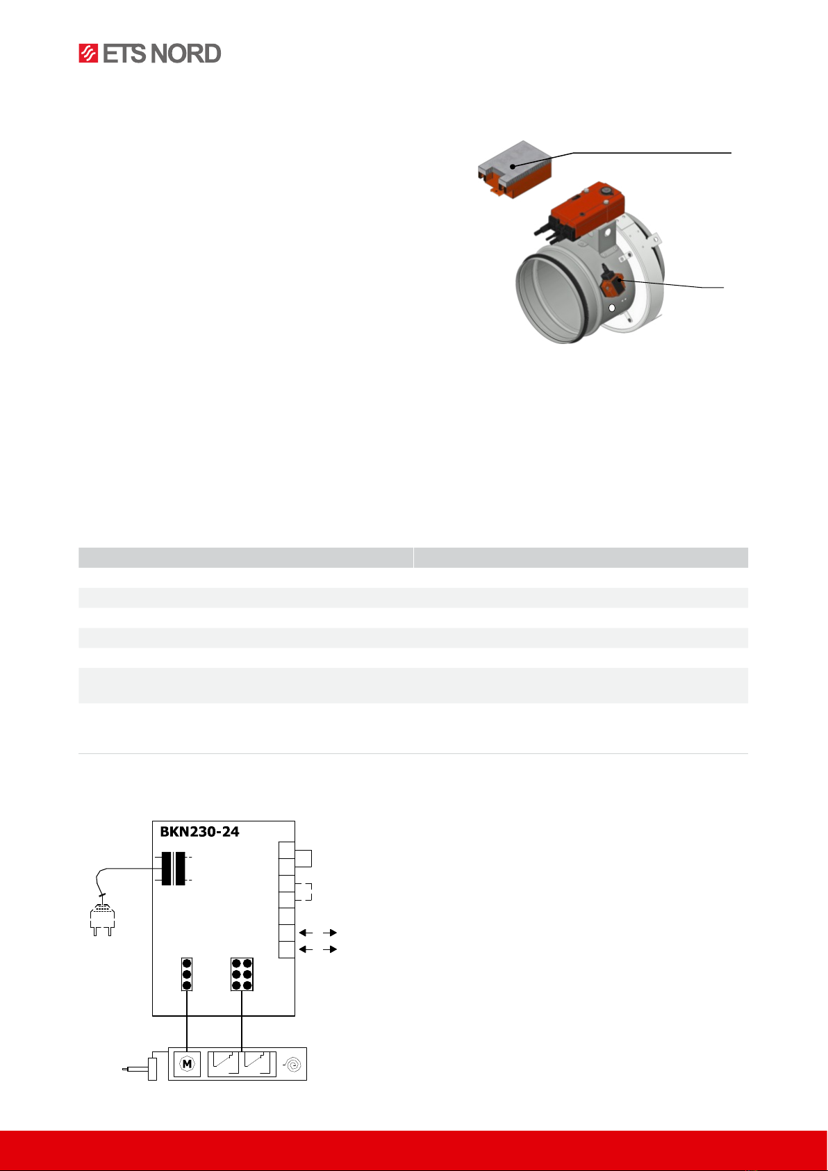
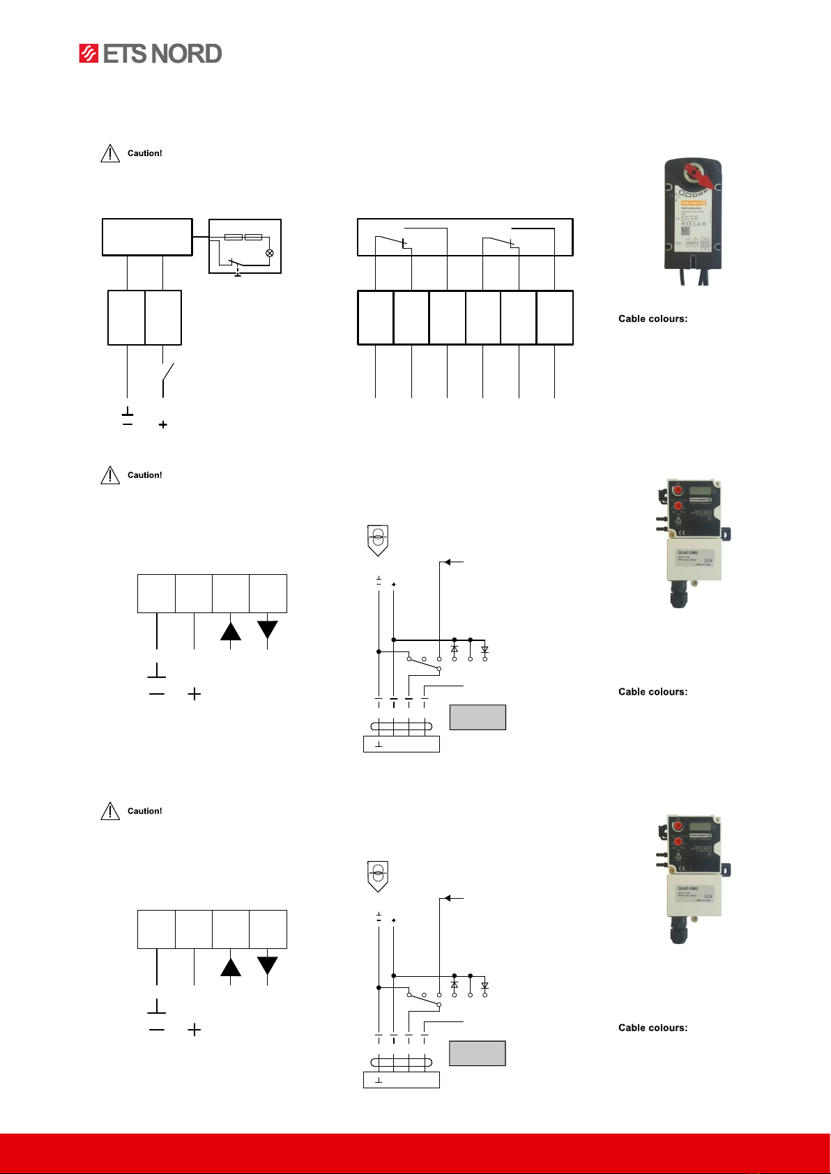
Wiring diagram of the BKN device with actuator, with act. mechanism BFL 24-T-ST, BFN 24-T-ST
1
2
3
4
5
6
7b
a
1)1)
2)
BAT
1) Bridge has been installed by the manufacturer. If needed, it can be removed ad
replaced with a thermoelectric starting mechanism. If terminals 1 and 2 are not
interconnected, safety function is initiated.
2) Bridge can be used only for starting and without BKS24… !
Two conductor wiring to BKS24
Communication unit BKN230-24
BAT

www.etsnord.com
8RDT-048-0423
®NORDfire |FDMS
2.6 Communication and Control Devices
BKS24-9A communication and control device is used for group control and checks of 1 to 9 fire dampers with the
actuator BFL (BFN)24-T-ST in connection with the supply and communication device BKN230-24. Signalization
of the damper blade position is individual for each damper (9 LED diodes), but the dampers can be controlled
and tested only as a group. BKS24-9A is intended for use in superordinate control system, which can display
operation mode and failure reports of the connected fire dampers. BKS24-9A receives signals from BKN230-24
through two wire cable. Proper damper operation is indicated by two light LED diodes:
Control LED “OPEN” = damper blade in emergency position OPEN
Control LED “CLOSE” = damper blade in safety position CLOSED
If the damper does not reach the required position within the preset time, the appropriate on-board FAULT LED
flashes and, at the same time, the fault contact K1 is activated (K1 is group alarm for all 9 dampers). This contact
is overridden as soon the defective damper reaches the required position. The on-board FAULT LED remains
on, until the fault is reset. Auxiliary contact K2 is provided for signaling the positions of dampers to a supreme
communication controlling system. The function of the auxiliary contact can be programmed via terminal 14
according the next table.
BKS24-9A contacts K1 and K2
K1 Function Contact Programming K2 Auxiliary Contact
Situation State Function Interconnection State
Current Failure K2 contact is on if all the
dampers are open
No Failure K2 contact is on if the
damper No. 1 is open
K2 contact is on if all the
dampers are closed
The BKS24-9A unit can be clipped directly onto a 35mm DIN mounting rail and external wiring is connected by
two 9-pin terminal connectors.
Functional testing can be performed by pressing the TEST pushbutton. While this button is held depressed, the
dampers run to the safe position. Any malfunctions are indicated by the internal FAULT LED´s.
15 16
14 11
17 18
15 16
14 12
14 open
15 16 14 11
17 18
15 16
14 12
14 open
15 16
14 11
17 18
15 16
14 12
14 open
15 16 14 11
17 18
15 16
14 12
14 open
15 16 14 11
17 18
15 16
14 12
14 open
15 16 14 11
17 18
15 16
14 12
14 open

Images are for illustrative purposes.
We reserve the right to make changes. RDT-048-0423 9
®NORDfire |FDMS
Technical data of the device BKS24-9A
Communication and Control Device BKS24-9A
Nominal voltage AC 24 V 50/60Hz
Power consumption 3,5 W (operating position)
Dimensioning 5,5 VA
Protection class III (safe small voltage)
Degree of protection IP 30
Ambient temperature 0 … +50 °C
Connection Terminals for conductor 2 × 1,5 mm2
3. Damper Design FDMS-VAV
3.1 Design .50 - Damper with Electrical Actuator
The damper is equipped with electric actuating mechanism. There are several actuators depending on the
damper size: GRUNER 340CTA-024D-XX-S2-V/8F12/ST06/BP8. To ensure the VAV function there is an Gruner
universal actuator controller GUAC-DM3 for air flow control and GUAC-PM3 for pressure control. After connec-
tion to the power supply AC/DC 24V, the actuating mechanism displaces the damper blade into operation
position given by the required air volume flow. At the same time is pre-stretched back spring inside the actuator.
When the actuator is under voltage (on power supply), the damper´s blade is in the position given by the required
air volume flow. The back spring is pre-stretched. If the power supply of the actuator is cut o (due to discon-
nection of power supply, or pressing the reset button on the thermo-electrical starting mechanism BAT (thermal
fuse), the back spring displaces the damper´s blade into the safety position “CLOSED”. The time needed for
displacing of the blade from the position “OPEN” to the position “CLOSE” takes maximal 20s. In the case that
the power supply is restored again (the blade can be in arbitrary position), the actuator starts re-displacing the
damper´s blade position given by the required air volume flow. The thermos-electrical mechanism BAT, which
contains two thermal fuses Tf1 and Tf2, is a part of actuator. These fuses are activated when temperature +72°C
has been exceeded. The fuse Tf1 measures the temperature in the outside of the damper and Tf2 measure the
temperature inside the air duct. Both fuses, they are in serial connection. It means in fact, that when one of them
is activated, the power supply of the actuator is cut-o and the actuator displaces the blade in safety position
“CLOSED”. The signalization of damper position “OPEN” or “CLOSED” is provided by two limit switches, which
are built-in inside the actuator. The fire damper has a part with controller consists of the body of the controller
with a control blade and pressure probes for determining the through-flow of air. A controller is axed to the
body for controlling the control blade, which is in this case the blade of the fire damper.
8
Wiring diagram BKS24-9A

www.etsnord.com
10 RDT-048-0423
®NORDfire |FDMS
3.2 GRUNER Actuator and Controller
GRUNER actuators 340CTA-024D-XX-S2-V/8F12/ST06/BP8 wiring diagram for mains voltage 24 VAC/DC
GRUNER controller GUAC-DM3 / GUAC-PM3 wiring diagram for mains voltage 24 VAC/DC
GRUNER controller GUAC-PM3 wiring diagram for mains voltage 24 VAC/DC
●Connect via safety isolation transformer!
●The device is not allowed to be used outside the specified field of application.
●It may only be installed by suitably trained personnel. Any legal regulations or
regulations issued by authorities must be observed during assembly.
BU = blue
BN = brown
BK = black
GY = Gray
~
YU
safety transformer
AC 24 V
DC 24 V
~
~
Y/Z U/PP
CAV-modes
(Default)
BU BN BK GY
U
DC 0...10 V
DC 2...10 V
open*
Vmax
closed*
Y
DC 0...10 V
DC 2...10 V
Vmin
2...10 V-close
0...10 V-close if Vmin=0
●Connect via safety isolation transformer!
●The device is not allowed to be used outside the specified field of application.
●It may only be installed by suitably trained personnel. Any legal regulations or
regulations issued by authorities must be observed during assembly.
BU = blue
BN = brown
BK = black
GY = Gray
~
YU
safety transformer
AC 24 V
DC 24 V
~
~
Y/Z U/PP
CAP-modes
(Default)
BU BN BK GY
U
DC 0...10 V
DC 2...10 V
open*
Pmax
closed*
Y
DC 0...10 V
DC 2...10 V
Pmin
2...10 V-close
0...10 V-close if Vmin=0
~
12
TA 72
TF1 TF2
LED
test
>80°
>5°
123456
S1 S2
WH WH WH WH WH WH
BU BN
●Connect through separating transformer!
●Parallel connection of other servo drives is possible. Respect power input data.
●Combination of mains voltage and use of signals from limit switches by very
low voltage is not allowed.
BU1 = blue
BN2 = brown
WH1 = white
WH2 = white
WH3 = white
WH4 = white
WH5 = white
WH6 = white
●Connect via safety isolation transformer!
●The device is not allowed to be used outside the specified field of application.
●It may only be installed by suitably trained personnel. Any legal regulations or
regulations issued by authorities must be observed during assembly.
BU = blue
BN = brown
BK = black
GY = Gray
~
YU
safety transformer
AC 24 V
DC 24 V
~
~
Y/Z U/PP
CAV-modes
(Default)
BU BN BK GY
U
DC 0...10 V
DC 2...10 V
open*
Vmax
closed*
Y
DC 0...10 V
DC 2...10 V
Vmin
2...10 V-close
0...10 V-close if Vmin=0
●Connect via safety isolation transformer!
●The device is not allowed to be used outside the specified field of application.
●It may only be installed by suitably trained personnel. Any legal regulations or
regulations issued by authorities must be observed during assembly.
BU = blue
BN = brown
BK = black
GY = Gray
~
YU
safety transformer
AC 24 V
DC 24 V
~
~
Y/Z U/PP
CAP-modes
(Default)
BU BN BK GY
U
DC 0...10 V
DC 2...10 V
open*
Pmax
closed*
Y
DC 0...10 V
DC 2...10 V
Pmin
2...10 V-close
0...10 V-close if Vmin=0
~
12
TA 72
TF1 TF2
LED
test
>80°
>5°
123456
S1 S2
WH WH WH WH WH WH
BU BN
●Connect through separating transformer!
●Parallel connection of other servo drives is possible. Respect power input data.
●Combination of mains voltage and use of signals from limit switches by very
low voltage is not allowed.
BU1 = blue
BN2 = brown
WH1 = white
WH2 = white
WH3 = white
WH4 = white
WH5 = white
WH6 = white

Images are for illustrative purposes.
We reserve the right to make changes. RDT-048-0423 11
®NORDfire |FDMS
Electrical parameters of GRUNER actuators 340CTA-024D-XX-S2-V/8F12/ST06/BP8
Actuating mechanism GRUNER 340CTA-024D-XX-S2-V/8F12/ST06/BP8
Nominal voltage 24V AC/DC 50/60 Hz
Power consumption - motoring
- holding
6,5 W
2,0 W
Dimensioning 7,5 VA
Protection class III
Degree of protection IP 54
Running time - motor
- spring return
< 100 s
< 20 s
Ambient Temperature
- normal duty
- safety futy
- non-operating temperature
-30 °C … +50 °C
> +75°C
-30 °C … +50 °C
Connecting - motor
- auxiliary switch
cable 1 m, 2 x 0,75 mm²
cable 1 m, 6 x 0,75 mm²
Thermal trips TF1 temperature inside Duct +72 °C
TF2 temperature outside Duct +71 °C
Electrical parameters of GRUNER controller GUAC-DM3
Controller GRUNER GUAC-DM3
Nominal voltage 24V AC/DC 50/60 Hz
Power consumption 0,6 W
Dimensioning 1,3 VA
Protection class III
Degree of protection IP 42
Control (0)2...10 VDC / Ri > (100 kΩ) 50 kΩ
(0)4...20 mA / Rext. = 500 Ω
Feedback signal (0)2...10 VDC, max. 0,5 mA
Priority control closed / Vmin / Vmax / open
Ambient Temperature
- normal duty
- storage temperature
0 °C … +50 °C
-20 °C … +80 °C
Connecting - controller
- actuators
screw terminals, 4-pin, 0,5...2,5 mm²
cable 1000 mm with Lumberg connector
Connection GUIV via diagnostic connector and feedback signal U/PP
Sensor 300 Pa (dynamic)
Communication PP-Bus (1200 Bd, max. 15 VDC)

www.etsnord.com
12 RDT-048-0423
®NORDfire |FDMS
Electrical parameters of Gruner controller GUAC-PM3
Controller GRUNER GUAC-PM3
Nominal voltage 24V AC/DC 50/60 Hz
Power consumption 0,6 W
Dimensioning 1,3 VA
Protection class III
Degree of protection IP 42
Control (0)2...10 VDC / Ri > (100 kΩ) 50 kΩ
(0)4...20 mA / Rext. = 500 Ω
Feedback signal (0)2...10 VDC, max. 0,5 mA
Priority control closed / Pmin / Pmax / open
Ambient Temperature
- normal duty
- storage temperature
0 °C … +50 °C
-20 °C … +80 °C
Connecting - controller
- actuators
screw terminals, 4-pin, 0,5...2,5 mm²
cable 1000 mm with Lumberg connector
Connection GUIV via diagnostic connector and feedback signal U/PP
Sensor 300 Pa (static)
Communication PP-Bus (1200 Bd, max. 15 VDC)
3.3 Types of Regulation FDMS-VAV
Now has the damper a given flow direction - important for the installation - AIRFLOW CONTROL
Pressure control - DUCT
Actuating mechanism
flow direction
∆p [ Pa ] - controller pressure loss
∆p
GUAC-DM3
Actuating mechanism
flow direction
Controller GUAC-PM3
∆p [ Pa ] - Static pressure difference between
∆p
duct and surrounding environment
s
s
air outlet
Room
Actuating mechanism
Controller GUAC-PM3
∆
p [ Pa ] - Static pressure difference between
room and surrounding environment
s
∆
p
s
Actuating mechanism
flow direction
∆p [ Pa ] - controller pressure loss
∆p
GUAC-DM3
Actuating mechanism
flow direction
Controller GUAC-PM3
∆p [ Pa ] - Static pressure difference between
∆p
duct and surrounding environment
s
s
air outlet
Room
Actuating mechanism
Controller GUAC-PM3
∆
p [ Pa ] - Static pressure difference between
room and surrounding environment
s
∆
p
s

Images are for illustrative purposes.
We reserve the right to make changes. RDT-048-0423 13
®NORDfire |FDMS
Pressure control - ROOM
4. Dimensions and Weights of FDMS
Actuating mechanism
flow direction
∆p [ Pa ] - controller pressure loss
∆p
GUAC-DM3
Actuating mechanism
flow direction
Controller GUAC-PM3
∆p [ Pa ] - Static pressure difference between
∆p
duct and surrounding environment
s
s
air outlet
Room
Actuating mechanism
Controller GUAC-PM3
∆
p [ Pa ] - Static pressure difference between
room and surrounding environment
s
∆
p
s
= for the actuator - BFL 86mm, BFN 110mm
= the height of the actuator - BFL 48mm, BFN 52mm
øD
p
222
50 5041
øD 69
øD1
70
øD
146
250
50 5041
øD 54
øD1
A
B 7
ca
M
ca
S
Blade overlaps - FDMS manual and thermal
= for the actuator - BFL 86mm, BFN 110mm
= the height of the actuator - BFL 48mm, BFN 52mm
øD
p
222
50 5041
øD 69
øD1
70
øD
146
250
50 5041
øD 54
øD1
A
B 7
ca
M
ca
S
Blade overlaps - FDMS with actuating mechanism
FDMS with mechanical control
øD
p
222
50 5041
øD 69
øD1
70
øD
146
250
50 5041
øD 54
øD1
A
B7
ca
M
ca
S
150
122
FDMS with actuating mechanism
øD
p
222
50 5041
øD 69
øD1
70
øD
146
250
50 5041
øD 54
øD1
A
B7
ca
M
ca
S
150
122

www.etsnord.com
14 RDT-048-0423
®NORDfire |FDMS
Size D
(mm)
D1
(mm)
c
(mm)
p
(mm) asaM
A
(mm)
B
(mm)
Design
.01, .11,
.80 (kg)
Design
.40, .50
(kg)
Actuator type
100 98 190 - 113 - - 86 48 2,2 3,3 BFL24-T(-ST), BFL230-T
125 123 215 - 113 - - 86 48 2,6 3,7 BFL24-T(-ST), BFL230-T
160 158 250 - 113 - - 86 48 3,2 4,3 BFL24-T(-ST), BFL230-T
180 178 270 2,5 113 - - 86 48 3,6 4,7 BFL24-T(-ST), BFL230-T
200 198 290 12,5 113 - - 86 48 4 5,1 BFL24-T(-ST), BFL230-T
225 223 315 25 163 - - 86 48 4,5 5,6 BFL24-T(-ST), BFL230-T
250 248 340 37,5 163 - - 86 48 5,1 6,2 BFL24-T(-ST), BFL230-T
280 278 370 52,5 163 - - 86 48 5,8 6,9 BFL24-T(-ST), BFL230-T
315 313 405 70 163 - 12 86 48 6,7 7,8 BFL24-T(-ST), BFL230-T
355 353 445 90 163 2 32 86 48 7,7 8,8 BFL24-T(-ST), BFL230-T
400 398 490 112,5 163 24,5 54,5 86 48 9 10,1 BFL24-T(-ST), BFL230-T
450 448 540 137,5 163 49,5 79,5 86 48 10,4 11,5 BFL24-T(-ST), BFL230-T
500 498 590 162,5 163 74,5 104,5 110 52 12 13,4 BFN24-T(-ST), BFN230-T
560 558 650 192,5 163 104,5 134,5 110 52 14,1 15,5 BFN24-T(-ST), BFN230-T
630 628 720 227,5 163 139,5 169,5 110 52 16,7 18,1 BFN24-T(-ST), BFN230-T
Weight of the communication unit BKN230-24 is 0,55 kg (used in design .60).
5. Dimensions and Weights of FDMS-VAV
14
50
50
41
575
146
125
D
D1
Ø
Ø
2 x D
Ø
min.
2 x D
Ø
min.
C
Blade overlaps - FDMS-VAV with actuating mechanism
14
50
50
41
575
146
125
D
D1
Ø
Ø
2 x D
Ø
min
.
2 x D
Ø
min
.
C
FDMS-VAV with actuating mechanism

Images are for illustrative purposes.
We reserve the right to make changes. RDT-048-0423 15
®NORDfire |FDMS
Size D
(mm)
D1
(mm)
c
(mm)
p
(mm) asaMDesign .50 (kg)
100 98 190 - 113 - - 4,3
125 123 215 - 113 - - 4,8
160 158 250 - 113 - - 5,6
180 178 270 2,5 113 - - 6,1
200 198 290 12,5 113 - - 6,6
225 223 315 25 163 - - 7,3
250 248 340 37,5 163 - - 8,1
280 278 370 52,5 163 - - 9,1
315 313 405 70 163 - 12 10,9
355 353 445 90 163 2 32 11,5
400 398 490 112,5 163 24,5 54,5 14,1
450 448 540 137,5 163 49,5 79,5 17,3
500 498 590 162,5 163 74,5 104,5 20,1
560 558 650 192,5 163 104,5 134,5 23,5
630 628 720 227,5 163 139,5 169,5 28,9
6. Material, Finishing
Damper bodies are supplied in the design made of galvanized steel plate without any other surface finishing.
The round duct joint is made of galvanized steel and boards from mineral fibers. Damper blades are made of fire
resistant asbestos free boards made of mineral fibers. Damper controls are made of galvanized materials with
no other surface finish. Springs are galvanized. Thermal protective fuses are made of sheet brass, thickness
=0.5 mm. Fasteners are made of galvanized steel.
According to the customer’s requirements, damper can be made of stainless material.
Specifications for stainless-steel models – classification of stainless steel:
• Class A2 – Food-grade stainless steel (AISI 304 – EN 17240)
• Class A4 – Chemistry-grade stainless steel (AISI 316, 316L – EN 17346, 17349)
The respective stainless steel is the material for all components present or accessing the damper interior;
components outside the damper body are typically from galvanised sheet metal (fasteners for mounting the
servo drive or mechanics, mechanics components except Item 4), frame components.
14
50
50
41
575
146
125
D
D1
Ø
Ø
2 x D
Ø
min.
2 x D
Ø
min.
C
Reccomended distance from double branch joint
14
50
50
41
575
146
125
D
D1
Ø
Ø
2 x D
Ø
min.
2 x D
Ø
min.
C
Reccomended distance from bend

www.etsnord.com
16 RDT-048-0423
®NORDfire |FDMS
The following components, including the fasteners, are made from stainless steel at all times:
• Damper body and all components permanently attached
• Leaf holders, including pins, metal parts of leaf
• Control components inside the damper (leaf angle selector, pin with lever)
• Mechanical components entering the interior of damper body (lower sheet of mechanics, lock holder
“1”, lock lever “2”, lock spring, 8 dia. stopper pin, mechanics pin)
• Inspection hole cover including the clip and fasteners (if they are parts of the cover)
• Bearing for torque transfer from the lever with pin on the angle selector at the leaf (made from
AISI440C)
The leaf of the damper is made from two Promatect-H sheets, thickness 15 mm, connected with stainless-steel
fasteners of corresponding class.
Plastic, rubber and silicon components, sealants, foaming bands, glass-ceramic seals, housings, brass bearings
of the leaf, servo drives, and end switches are identical for all material variants of the dampers.
The thermal link is identical for all material variants of the dampers. Upon specification by customer, the thermal
link may be made from A4 from stainless steel sheet metal.
The temperature-dependent initiator of the servo drive (sensor) is modified for stainless-steel variants of the
dampers; the standard galvanised screws are replaced with stainless-steel M4 screws of corresponding class
the counterpart has stainless-steel riveting M4 nuts.
Some fasteners and components are available in one class of stainless steel; the type will be used in all stain-
less-steel variants.
The leaf in the variants for chemical environments (Class A4) is always treated with a coating of chemically
resistant Promat SR.
Any other requirements for the design shall be considered atypical and shall be addressed on an individual basis.
7. Technical Data of FDMS and FDMS-VAV
7.1 Pressure Loss
Caution:
All the data is valid for dampers
in the full “OPEN” position!
1,0
10,0
100,0
10 100 1000 10000
Air flow (m
3
/h)
Pressure drop (Pa)
200
14000
Air flow (m
3
/h)
Pressure drop (Pa)
200
14000
FDMS

Images are for illustrative purposes.
We reserve the right to make changes. RDT-048-0423 17
®NORDfire |FDMS
Caution:
All the data is valid for dampers
in the full “OPEN” position!
7.2 Air Volume Flow
Size
Air volume (m3/h) Vnom
Minimum (w=1 m/s) Maximum (w=7 m/s)
m3/h l/s m3/h l/s m3/h l/s
100 30 8 200 56 200 56
125 45 13 310 86 310 86
140 55 15 400 111 400 111
160 70 19 500 139 500 139
180 90 25 650 181 650 181
200 115 32 800 222 800 222
225 145 40 1000 278 1000 278
250 180 50 1250 347 1250 347
280 220 61 1550 431 1550 431
315 280 78 2000 556 2000 556
355 355 99 2500 694 2500 694
400 455 126 3200 889 3200 889
500 710 197 5000 1389 5000 1389
630 1120 311 7900 2194 7900 2194
7.3 Operating Mode and Setup
GUAC-DM3
Operating mode
Through connecting the power supply to BU+BN (1+2) and a reference signal Y to BK (3) in the range of (0)2…10
VDC, the connected actuator regulates to the set point. The current flow in % of Vnom is provided as a feedback
signal U on GY (4) for other actuators and can be communicated via PP-Bus.
CAP modes / override controls: AC*/DC signal to terminal BK (3)
The controller is overload-proof.
Edit
The selector allows the changing of values. The position of the arrow shows the value set. The changes are
displayed as soon as the selector is moved ±10° from the position.
1,0
10,0
100,0
10 100 1000 10000
Air flow (m
3
/h)
Pressure drop (Pa)
200
14000
Air flow (m
3
/h)
Pressure drop (Pa)
200
14000
FDMS-VAV

www.etsnord.com
18 RDT-048-0423
®NORDfire |FDMS
Flow/Unit
Setting the desired actual volume flow unit in m³/h and l/s.
Vmin
Adjust the desired flow Vmin (setpoint Y = 0 / 2 VDC).
Vmax
Adjust the desired flow Vmax (setpoint Y = 10 VDC).
Diag
Diagnostic menu:
o - diagnostic mode is o
on - diagnostic mode is on
oP - opens the damper
cL - closes the damper
Lo - activated Vmin
Hi - activated Vmax
123 - software version
Mode
Setting the direction of rotation:
0-n...0-10 VDC normal
2-n...2-10 VDC normal
0-i ...0-10 VDC invers
2-i ...2-10 VDC invers
Vnom
Setting the nominal volumetric flow depending on the VAV-box.
GUAC-PM3
Operating mode
Through connecting the power supply to BU+BN (1+2) and a reference signal Y to BK (3) in the range of (0)2…10
VDC, the connected actuator regulates to the specified set point. The current pressure in % of Pnom is provided
as a feedback signal U on GY (4) for other actuators and can be communicated via PP-Bus.
CAP modes / override controls: AC*/DC signal to terminal BK (3)
The controller is overload-proof.
Edit
The selector allows the changing of values. The position of the arrow shows the value set. The changes are
displayed as soon as the selector is moved ±10° from the position.
Pres / Unit
Setting the desired actual pressure unit to Pa and H2O.
Pmin
Adjust the desired flow Pmin (setpoint Y = 0 / 2 VDC).
Pmax
Adjust the desired flow Pmax (setpoint Y = 10 VDC).
Dig
Diagnostic menu:
o - diagnostic mode is o
on - diagnostic mode is on
oP - opens the damper
cL - closes the damper
Lo - activated Vmin
Hi - activated Vmax
123 - software version

Images are for illustrative purposes.
We reserve the right to make changes. RDT-048-0423 19
®NORDfire |FDMS
Mode
Setting the direction of rotation:
0-n...0-10 VDC normal
2-n...2-10 VDC normal
0-i ...0-10 VDC invers
2-i ...2-10 VDC invers
Pnom
Shows the nominal pressure setting.
7.4 Noise Data FDMS / FDMS-VAV
Level of acoustic power corrected with filter A
LwA -
acoustic power level corrected with filter A (dB(A))
f - frequency in octave range (Hz)
w - air flow velocity (m/s)
Caution: All the data is valid for dampers in the full “OPEN” position!
LwA value for size 100 (dB(A))
f (Hz) w (m/s)
2 3 4 5 6 7 8 9 10 11 12
63 < 2 < 2 2 8 13 16 19 22 25 27 29
125 < 2 4 12 18 23 27 31 34 36 39 41
250 < 2 8 17 24 29 34 37 41 44 46 49
500 < 2 9 18 26 31 36 40 44 47 50 53
1000 < 2 5 16 24 30 35 40 43 47 50 53
2000 < 2 < 2 10 18 25 30 35 39 43 46 49
4000 < 2 < 2 < 2 9 16 22 27 32 36 39 43
8000 < 2 < 2 < 2 < 2 5 11 16 21 25 29 32
Total < 15 < 15 23 30 36 41 45 49 52 55 57
LwA value for size 125 (dB(A))
f (Hz) w (m/s)
2 3 4 5 6 7 8 9 10 11 12
63 < 2 < 2 < 2 5 9 13 16 19 21 23 25
125 < 2 < 2 8 15 20 24 27 30 33 35 37
250 < 2 4 13 20 26 30 34 37 40 43 45
500 < 2 5 15 22 28 33 37 41 44 47 49
1000 < 2 < 2 12 20 26 32 36 40 43 46 49
2000 < 2 < 2 6 14 21 27 32 36 39 43 46
4000 < 2 < 2 < 2 6 13 19 24 28 32 36 39
8000 < 2 < 2 < 2 < 2 < 2 7 13 18 22 25 29
Total < 15 < 15 19 26 32 37 41 45 48 51 54

www.etsnord.com
20 RDT-048-0423
®NORDfire |FDMS
LwA value for size 160 (dB(A))
f (Hz) w (m/s)
2 3 4 5 6 7 8 9 10 11 12
63 < 2 < 2 < 2 5 10 13 16 19 22 24 26
125 < 2 < 2 9 15 20 24 27 31 33 36 38
250 < 2 5 14 21 26 31 34 38 41 43 46
500 < 2 6 15 23 28 33 37 41 44 47 50
1000 < 2 2 13 21 27 32 37 40 44 47 50
2000 < 2 < 2 7 15 22 27 32 36 40 43 46
4000 < 2 < 2 < 2 6 13 19 24 29 33 36 40
8000 < 2 < 2 < 2 < 2 < 2 8 13 18 22 26 29
Total < 15 < 15 20 27 33 38 42 45 49 52 54
LwA value for size 180 (dB(A))
f (Hz) w (m/s)
2 3 4 5 6 7 8 9 10 11 12
63 < 2 < 2 < 2 4 9 13 16 18 21 23 25
125 < 2 < 2 8 14 19 23 27 30 32 35 37
250 < 2 4 13 20 25 30 34 37 40 42 45
500 < 2 5 15 22 28 33 37 40 43 46 49
1000 < 2 < 2 12 20 26 31 36 40 43 46 49
2000 < 2 < 2 6 14 21 27 31 35 39 42 45
4000 < 2 < 2 < 2 6 13 19 24 28 32 36 39
8000 < 2 < 2 < 2 < 2 < 2 7 12 17 21 25 29
Total < 15 < 15 19 26 32 37 41 45 48 51 54
LwA value for size 200 (dB(A))
f (Hz) w (m/s)
2 3 4 5 6 7 8 9 10 11 12
63 < 2 < 2 < 2 5 10 13 17 19 22 24 26
125 < 2 < 2 9 15 20 24 28 31 33 36 38
250 < 2 5 14 21 26 31 35 38 41 43 46
500 < 2 6 15 23 29 33 38 41 44 47 50
1000 < 2 3 13 21 27 32 37 41 44 47 50
2000 < 2 < 2 7 15 22 27 32 36 40 43 46
4000 < 2 < 2 < 2 6 14 19 25 29 33 37 40
8000 < 2 < 2 < 2 < 2 < 2 8 13 18 22 26 30
Total < 15 < 15 20 27 33 38 42 46 49 52 55
LwA value for size 225 (dB(A))
f (Hz) w (m/s)
2 3 4 5 6 7 8 9 10 11 12
63 < 2 < 2 < 2 4 9 12 15 18 21 23 25
125 < 2 < 2 8 14 19 23 27 30 32 35 37
250 < 2 4 13 20 25 30 33 37 40 42 45
500 < 2 5 14 22 27 32 36 40 43 46 49
1000 < 2 < 2 12 20 26 31 36 39 43 46 49
2000 < 2 < 2 6 14 21 26 31 35 39 42 45
This manual suits for next models
1
Table of contents
Other ETS NORD Fire And Smoke Damper manuals

ETS NORD
ETS NORD NORDfire User manual

ETS NORD
ETS NORD FDMA-PM Series User manual

ETS NORD
ETS NORD NORDfire SEDM-L User manual

ETS NORD
ETS NORD NORDfire SEDM User manual

ETS NORD
ETS NORD NORDfire User manual

ETS NORD
ETS NORD NORDfire FDMB User manual

ETS NORD
ETS NORD NORDfire SEDS-L User manual

ETS NORD
ETS NORD NORDfire User manual

ETS NORD
ETS NORD FDMS Guide
Popular Fire And Smoke Damper manuals by other brands

Mandik
Mandik FDMQ manual

JRClancy
JRClancy 016-410L installation instructions

SMAY
SMAY WKP-O Technical documentation

Mandik
Mandik SEDS-L Technical specifications

Trox Technik
Trox Technik AKK Assembly and operating instructions

Mandik
Mandik FDMR Installation, operation, maintenance and service instructions