Ewimar CONV Pelco to Bosch User manual

CONV Pelco To Bosch - firmware 0.01.xx
Ewimar Sp. z o.o.
www.ewimar.pl Made in Poland
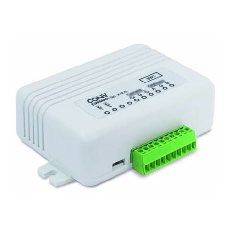
The converter / translator is a microprocessor device designed to integrate control devices using
the Pelco-D or Pelco-D protocol with Bosch Speed Dome cameras operating in the Biphase or OSRD
protocols.
High performance processor and software created in accordance with the principles of
multitasking, give an efficient configuration with fast response to control.
The converter / translator is equipped with one RS-485 port for Pelco protocol and two
configurable ports for Biphase / RS-485 OSRD.
Main features
1) Support for up to sixteen cameras (Standard version) by one converter with individually selected
addresses for each camera in the range from 1-254. One camera support for Lite version.
2) Possibility to extend up to 99 cameras by purchasing additional licenses. Function of changing
camera output addresses (ADDRESS SHIFT) during translation. It also allows you to control Bosch
cameras with an address range of 1-16383. Optional license for the Standard version, free for the
Lite version.
3) Advanced PAN / TILT Joystick Curve Correction function, individually for each camera - optional
license for the Standard version, free for the Lite version.
4) Simultaneous processing of many motion commands: Pan, Tilt, Zoom, Iris, Focus.
5) Programming and calling the PRESET and AUX functions.
6) Wide range of baud rate selection and Pelco and Bosch OSRD protocol type selection.
7) Settings and updating firmware via USB and Ewimar Firmware Upgrader / Configurator.
8) Possibility to change the firmware to others when the converter will no longer be used in the existing
system - only at the cost of the software.
Connection structure
The converter has two Bosch output ports, each of which is freely configurable as Biphase or OSRD
(RS-485). It is installed between a control device with Pelco protocol (keyboard, DVR, encoder, etc.) and
Bosch cameras. Can be located anywhere between control device and PTZ cameras..
PORT 1 / RS485 PORT 3
PTZ keyboard with
Pelco
Bosch Speed
Dome
PORT 2
Biphase / OSRD
Biphase / OSRD
Pelco
Speed Dome
Pelco->Bosch
The basic way to connect a Pelco PTZ keyboard to Bosch Speed Dome cameras
CONVAG Pelco To Bosch
PTZ protocol converter / translato
r
USER GUIDE firmware 0.01.xx Standard and Lite version

CONV Pelco To Bosch - firmware 0.01.xx
Ewimar Sp. z o.o.
www.ewimar.pl Made in Poland
Description of configuration and connection elements
110
POWER / COMMUNICATION PORTS – Removable terminal containing converter power terminals and
RS-485 / BIPHASE communication ports. The purpose of each port is described below.
LED DIODES.
Red – depending on the settings, informs about translation and sending data to the camera or
informs about corrupted data packets / collisions, coming from the control device.
Green – depending on the settings informs about any data coming from the control device or
about the correct packets only (correct protocol and transmission parameters). Signaling that
the correct packets have been received does not mean that they will be translated, because it
also depends on settings the supported addresses by the converter.
DIP SWITCHES – Designed to switch on termination resistors for ports 1 ~ 3 and to run the converter
firmware update mode. If ports 2 or 3 are configured as Biphase, switches 2 or 3 should be
ON.
USB – It is designed to configure settings using the Firmware Upgrader / Configurator and to perform
software updates / changes
Power AC/DC
Power AC/DC
485 - A(+)
110
485 - B(-)
GND
485 - A(+)
485 - B(-)
GND
485 - A(+)
485 - B(-)
}
}
}
Bosch Speed Dome
Bosch Speed Dome
A
B
GND
C+
C-
GND
C+
C-
GND
POWER - Connect a power source in the range 9 ~ 24V AC / DC - any polarity.
GND – Power Ground RS-485 communication ports. It is recommended to connect with cameras and
keyboards to avoid damage due to the ground loop effect.
POWER / COMMUNICATION PORTS
USB LED DIODES DIP SWITCHES

CONV Pelco To Bosch - firmware 0.01.xx
Ewimar Sp. z o.o.
www.ewimar.pl Made in Poland
PORT1 – Input port for connecting a PTZ keyboard with Pelco-P or Pelco-D protocol. The Pelco protocol
type and baud rate is set using the Configuration software (by default: Pelco-D, 9600baud).
PORT2 – Configurable output port for Bosch cameras, controlled by RS-485 (OSRD) or Biphase.
PORT3 – Configurable output port for Bosch cameras, controlled by RS-485 (OSRD) or Biphase.
Settings and available functions
Configuration of the converter is carried out using the software available at:
www.ewimar.com/soft/configurator.rar - the file contains drivers and operating manuals needed to
run.
Configuration of the converter is done after connecting it to a PC with a standard USB cable. The
converter is detected as another COM port with fast data transmission.
The converter is connected to the software by selecting the COM port (the converter is detected as a
USB serial port) and clicking the "Connect" button.
The "Get user manual" button opens the current User Manual for the firmare version of the converter in
the default web browser. It may contain more detailed information than paper manuals. To open the
manual you need an internet connection and installed PDF browser. Web address to the manual is also
displayed after reading the converter configuration.
The "Get Current Configuration" button displays the current converter configuration settings in the left
panel. The "Command list" button displays a list of commands available for the current firmware version
along with the command's syntax and range of input data.
The right panel displays the command sent to the converter and its response about a changed setting or
an error.
Each command must be entered in full syntax (letters, dashes, etc.) and the allowable range of
data. The x, y characters must be replaced by the appropriate value.
The following parameters are defined in the converter:
1. Protocol type for Port 1: Command „P1-x”.
Selection of communication protocol for the PTZ keyboard: P1-0 = Pelco-D, P1-1 = Pelco-P.
2. Protocol type for Port 2: Command „P2-x”.
Selection of communication protocol for the Speed Dome: P2-0 – Biphase, P2-1 - OSRD.
3. Protocol type for Port 3: Command „P3-x”.
Selection of communication protocol for the Speed Dome: P3-0 – Biphase, P3-1 - OSRD.
4. Baud rate: Command „Bx-y”.
Used to select the baud rate for each ports in the range 1200 – 115200 baud.
The xmeans port number (1-3), ymeans baud rate (0-8). Notice! After set port 2 or 3 to Biphase
the baud rate can’t changed.
Example: To set the speed 9600baud for port 1, enter „B1-3”.
5. Green LED: Command „DG-x”.
Configuration for Green LED operation. DG-0 – Indicates of any data received from on the Port 1,
regardless of the protocol setting or transmission speed.
DG-1 – Indicates of receiving only the correct packets on Port 1.
DIP-SW
12 43
ON
Dip switches No 1~3 are designed to turn on termination resistors accordingly for ports
1~3. After set to ON, internal 120Ωresistor is connected between A and B of according
port.
Dip switch No 4 is used to emergency firmware update if during normal update
communication has been lost. This way to repair broken firmware. To activate emergency
update mode set DIP No 4 to ON and restart power supply (reconnect the USB). For
normal operation DIP No 4 must be in OFF position. Emergency update method has been
decribed in manual of the Firmware Upgrader / Configurator.

CONV Pelco To Bosch - firmware 0.01.xx
Ewimar Sp. z o.o.
www.ewimar.pl Made in Poland
6. Red LED: Command „DR-x”.
Configuration for Red LED operation. DR-0 – Indicates the translation and sending commands to
Bosch cameras - only if the controlled camera address is configured in the converter.
DR-1 – Indicates wrong packets received on Port 1 - wrong protocol, incorrect transmission
speed or transmission errors due to the use of poor quality cable..
7. Supported camera addresses: Command „CAx-y”.
The converter contains a camera table, the capacity of which depends on the license entered - by
default 16 for the Standard version and 1for the Lite version. The table should be assigned
camera addresses in the range from 1-254, which will be supported by the converter.
The xcharacter mean the position number in the table, ymean supported camera address (1-
255) entered at that position.
Choose the position number and assign an address to it. Example: To assign camera address
128 to position No 1, enter: CA1-128.
The order of the addresses in the table does not matter if the addresses repeat, only the first one
matters.
8. Special: Command „Sxxxxxx”.
Execution of a special command, for example entering the license code..
9. Address shift: Command „CSx-y”.
Described in the extended manual downloaded with the " Get user manual " button.
Always active in Lite version, active in Standard version after purchasing the license.
10. Advanced joystick correction: Command „CPx-y” i „CTx-y”.
Described in the extended manual downloaded with the " Get user manual " button.
Always active in Lite version, active in Standard version after purchasing the license.
List of translated commands from the Pelco keyboard
Controlling the camera using a Pelco keyboard directly depends on its functionality..
Nr Command from Pelco keyboard Bosch camera function
1 Move Up / Down / Left / Right Move Up / Down / Left / Right
2 Zoom in / Zoom out Zoom + / Zoom -
3 Focus Far / Focus Near Focus Far / Focus Near
4 Iris open / Close Iris Open / Close
5 Auto Pan Scan 360˚(AUX-1-ON)
6 Auto Scan Auto scan with left / right limit (ON-2-ENTER)
7 Left limit Set left limit for Auto Scan (SET-101-ENTER)
8 Right limit Set right limit for Auto Scan (SET-102-ENTER)
9 Learn Pattern ( Dowolny numer) Pattern A record (ON-100-ETER)
10 Stop Learn ( Dowolny numer) End record Pattern A (OFF-100-ENTER)
11 Run Pattern ( Dowolny numer) Continuous Playback Pattern A (ON-50-ENTER)
12 Call Preset 95 Entry to menu (ON-46-ENTER)
13 Call preset 96 Unlock advanced menu (OFF-90-ENTER)
14 Call preset 97 Disable OSD (OFF-46-ENTER)
15 Call preset 101 Show left limit (SHOT-101-ENTER)
16 Call Preset 102 Show right limit (SHOT-102-ENTER)
17 Call preset 111 Stop record pattern A (OFF-100-ENTER)
18 Call preset 112 Stop record pattern B (OFF-101-ENTER)
19 Call preset 113 Edit Tour 2 Custom (SHOT-900-ENTER)
20 Call preset 114 Auto Pan/Scan 1 Speed (ON-14-ENTER) minus
21 Call preset 115 Tour Speed 1 (ON-15-ENTER) minus
22 Call preset 116 Scan left / light (ON-2-ENTER)
23 Call preset 120 Continuous Playback Pattern A (ON-50-ENTER)
24 Call preset 121 Single Playback Pattern A (ON-51-ENTER)
25 Call preset 122 Continuous Playback Pattern B (ON-52-ENTER)

CONV Pelco To Bosch - firmware 0.01.xx
Ewimar Sp. z o.o.
www.ewimar.pl Made in Poland
26 Call preset 123 Single Playback Pattern B (ON-53-ENTER)
27 Call preset 124 Clear Alarm (OFF-65-ENTER)
28 Call preset 125 Start Autotracking (ON-78-ENTER)
29 Call preset 126 Run Tour Custom (ON-7-ENTER)
30 Call preset 127 Run Tour (ON-8-ENTER)
31 Call preset 128 Start other AUX OFF procedure
32 Call preset 1-99 SHOT 1-99
33 Set preset 96 Lock menu (ON-90-ENTER)
34 Set preset 97 Enable OSD (ON-46-ENTER)
35 Set preset 98 Pre-position Title menu (ON-62-ENTER)
36 Set preset 99 Zone Title menu (ON-63-ENTER)
37 Set preset 100 Enters the Pre-position menu (SET-100-ENTER)
38 Set preset 101 Set–programs left limit (SET-101-ENTER)
39 Set preset 102 Set–programs right limit (SET-102-ENTER)
40 Set preset 105 Access the password menu (SET-802-ENTER)
41 Set preset 106 Display current address (ON-997-ENTER)
42 Set preset 107 Display and program current address (ON-998-ENTER)
43 Set preset 108 Display and program unaddressed (ON-999-ENTER)
44 Set preset 109 Inactivity mode(ON-9-ENTER)
45 Set preset 110 Go to home position (SET-110-ENTER)
46 Set preset 111 Record pattern A (ON-100-ETER)
47 Set preset 112 Record pattern A (ON-101-ETER)
48 Set preset 113 Tour edit 1 (ON-900-ETER)
49 Set preset 114 Auto Pan/Scan 1 (ON-14-ENTER) plus
50 Set preset 115 Tour Speed 1 (ON-15-ENTER) plus
51 Set preset 128 Start other AUX ON procedure
32 Set preset 1-99 SET SHOT 1-99
Activation of any AUX ON / AUX OFF number
Bosch cameras support 1023 AUX commands, which are intended for performing special functions,
among others for remote address setting (Fast-address).
Because the Pelco protocol does not allow for the transmission of such information, the converter has a
special procedure for activating the AUX function using a combination of Set Preset / Call Preset
commands. The rules and examples of sending AUX commands are described below.
Moving the joystick between individual steps or performing other operations cancels the AUX procedure.
Entering values outside the range also cancels the AUX procedure.
NOTICE! The described procedure only works correctly with keyboards that send preset commands only
once at start-up. Some keyboards may send a PRESET command twice, in which case the AUX function
cannot be used.
SEND AUX ON 1~99
[SET PRESET 128] + [SET PRESET 1~99] + [SET PRESET 128]
Start procedure Value Enter
SEND AUX ON 101 – 1023
[SET PRESET 128] + [SET PRESET 1~10] + [SET PRESET 1~99]
Start procedure Value * 100 Value *1

CONV Pelco To Bosch - firmware 0.01.xx
Ewimar Sp. z o.o.
www.ewimar.pl Made in Poland
Pelco preset numbers start with 1, therefore use the 100 preset to enter 00 as the second digit. The
same rule applies to AUX 200, 300, 400 ... etc.
AUX ON 200: [SET PRESET 128] + [SET PRESET 2] + [SET PRESET 100]
-------------------------------------------------------------------------------------------------------------------------------
SEND AUX OFF 1~99
[CALL PRESET 128] + [CALL PRESET 1~99] + [CALL PRESET 128]
SEND AUX OFF 101 - 1023
[CALL PRESET 128] + [CALL PRESET 1~10] + [CALL PRESET 1~99]
Pelco preset numbers start with 1, therefore use the 100 preset to enter 00 as the second digit. The
same rule applies to AUX 200, 300, 400 ... etc.
AUX OFF 100: [SET PRESET 128] + [SET PRESET 1] + [SET PRESET 100]
-------------------------------------------------------------------------------------------------------------------------------
Examples:
SEND AUX ON 50
[SET PRESET 128] + [SET PRESET 50] + [SET PRESET 128]
SEND AUX OFF 101
[CALL PRESET 128] + [CALL PRESET 1] + [CALL PRESET 1]
SEND AUX ON 100
[SET PRESET 128] + [SET PRESET 1] + [SET PRESET 100]
SEND AUX ON 997
[SET PRESET 128] + [SET PRESET 9] + [SET PRESET 97]
Example of remote FastAddress address change for camera G4 series.
Step Command Sequence from the Pelco keyboard A message on the screen after send
command
1 Select the target camera number from the keyboard to which you want to change the address from any other
cameras. Carefully observe the messages on the screen, they will appear on all Bosch cameras at the same time,
however, some of them may be different than those presented below; it depends on current address and model.
ON-999-ENTER [Set preset 128]+ [Set preset 9] + [Set preset 99] To change or delete address, Enter ON-224-
ENTER
2 ON-224-ENTER [Set preset 128] + [Set preset 2] + [Set preset 24] To continue FastAddressing, Enter ON-240-
ENTER
3 ON-240-ENTER [Set preset 128] + [Set preset 2] + [Set preset 40] To write new address,
Enter ON-1-ENTER
4 ON-1-ENTER [Set preset 128]+ [Set preset 1] + [Set preset 128] Nev Fastaddress: (new address)

CONV Pelco To Bosch - firmware 0.01.xx
Ewimar Sp. z o.o.
www.ewimar.pl Made in Poland
Known problems and their solutions
No control Bosch Speed Dome - the green LED blinks during control, the red LED does not blink
1. Set the green LED to display only valid packets.
2. If the green LED is not blinking, check the connection and transmission parameters.
3. If the green LED is blinking, check if the camera address you want to control is set in the converter.
No control Bosch Speed Dome – the green LED blinks on the control, the red LED blinks from time to time.
1. Check the correct connection between the converter and the keyboard.
2. Check if the RS-485 terminating resistors are included in the keyboard and converter, if the distance
between the converter and the keyboard are over 100m
3. Check the power supply stability of the converter
No control Bosch Speed Dome – green and red LED blinks.
1. Check the correct connection of the cables between the converter and the camera.
2. Check if the Bosch output protocol is suitable for the controlled cameras, check for OSRD transmission
speed
3. Check if the termination switch for the Bosch port is included. For Biphase it should be attached.
4. Check the camera address settings.
Time to time there is no camera control or the camera rotates continuously and cannot be stopped.
1. Set the red LED to display erroneous packets.
2. If the red LED blinks frequently, transmission is interrupted as a result of incorrect connections or data
collision with another control device.
3. Check if the termination resistors are included in the converter and in the camera.
4. Possible interference from the ground loop effect - a data separator is required.
No LEDs light up when attempting to control.
1. Set the green LED to display all data.
2. If the green LED is blinking, verify the baud rate and protocol settings on PTZ keyboard and in the
converter.
3. If the green LED is not blinking, check the connections between the keyboard and the converter.
4. Check the converter power supply. Restart power - after connecting power supply red diode should blinks
several times.
The device failed to start despite the above tips? Contact Ewimar Sp z o.o. Technical Support.
The converter is a specialized product and to connect and run this product, basic electronic knowledge,
knowledge of communication interfaces and issues related to the installation of CCTV devices are
necessary. The manufacturer is not liable for losses related to the use of the device, failure to operate or
damage caused by the lack of proper knowledge of the user. This manual does not convey general
knowledge, only information applicable to this product.
In the absence of operation or malfunction of the device or any complaint, please contact the
manufacturer immediately.

CONV Pelco To Bosch - firmware 0.01.xx
Ewimar Sp. z o.o.
www.ewimar.pl Made in Poland
DECLARATION OF CONFORMITY
PRODUCT:
PTZ Protocol Converter
MODEL:
CONV Pelco to Bosch
MANUFACTURER:
Ewimar Sp. z o.o.
ul. Konarskiego 84, 01-355 Warszawa
We hereby declare that the above product is approved for work within the EU and is compliant with
essential requirements and other relevant provisions of EMC Directives 2014/30 / EU and 2011/65 / EU -
RoHS directive:
PN-EN 61000-6-3: 2008 / A1: 2012 - Electromagnetic compatibility (EMC) - Part 6-3: General standards -
Emission standard in residential, commercial and slightly industrialized environments
Warsaw 23 February 2020 r. Ewimar Sp. z o.o.
Manufacturer:
Table of contents
Other Ewimar Media Converter manuals
Popular Media Converter manuals by other brands
Omnitronic
Omnitronic LITTLE HELPER Series user manual
Intelligent Motion Systems
Intelligent Motion Systems RS-232 to RS-422 Converter CV-3222 operating instructions
RGBlink
RGBlink FLEX 8 user manual
B&B Electronics
B&B Electronics 4WSD9R Product information
Nortel
Nortel CWDM SFP installation guide
RSF Elektronik
RSF Elektronik AK MSS 25 1 Vss Mounting instructions
