Ewimar CONV Bosch To Pelco Standard User manual

CONV Bosch To Pelco - firmware 0.01.xx
Ewimar Sp. z o.o.
www.ewimar.pl Made in Poland
The converter / translator is a microprocessor device designed to integrate Bosch CCTV system
with other Speed Dome cameras using Pelco-D or Pelco-D protocol.
High performance processor and software created in accordance with the principles of
multitasking, give an efficient configuration with fast response to control.
The converter / translator is equipped with one input port OSRD (RS-485) / Biphase for Bosch
and two independent output ports for Pelco-D and Pelco-P.
Converter Standard version can be used in CCTV systems where only one Bosch PTZ
keyboard is used. For systems with multiple PTZ keyboards LITE version should be used for
stable operation - one protocol converter per one Speed Dome.
Main features
1) Support for up to sixteen cameras (Standard version) by one converter with individually selected
addresses for each camera in the range from 1-254. One camera support for Lite version.
2) Possibility to extend up to 99 cameras by purchasing additional licenses.
3) Function of changing camera output addresses (ADDRESS SHIFT) during translation. It also allows
to cameras with DVR’s or Video Matrix using address range of 1-16383. Optional license for the
Standard version, free for the Lite version.
4) Advanced PAN / TILT Joystick Curve Correction function, individually for each camera - optional
license for the Standard version, free for the Lite version.
5) Simultaneous processing of many motion commands: Pan, Tilt, Zoom, Iris, Focus.
6) Programming and calling the PRESET and AUX functions.
7) Wide range of baud rate selection and Pelco and Bosch OSRD protocol type selection.
8) Settings and updating firmware via USB and Ewimar Firmware Upgrader / Configurator.
9) Possibility to change the firmware to others when the converter will no longer be used in the existing
system - only at the cost of the software.
Supported protocols Bosch/Philips
Translation process takes into account a feew motion commands for Bosch.
Fixed-Start-Stop (optocode 0x02) – The command sends START and STOP, with no information
about the speed of movement. Command used in old type PTZ telemetry receivers and heads. The
Pan/Tilt Speed for Pelco Speed Dome during translation is as set by commands Pan Speed for Fixed
and Tilt Speed for Fixed.
Fixed-speed for Specified Period (optocode 0x03) – The command sends START and STOP with no
information about the speed of movement. The movement is active by defined time. The Pan/Tilt Speed
for Pelco Speed Dome during translation is as set by commands Pan Speed for Fixed and Tilt Speed
for Fixed.
Fixed-Repetive (optocode 0x04) – The command sending only the START at intervals up to every
50ms (20Hz), with no information about the speed of rotation. Used in old type PTZ telemetry receivers
and heads. It does not support Iris Close and Iris Open.The Pan/Tilt Speed for Pelco Speed Dome
during translation is as set by commands Pan Speed for Fixed and Tilt Speed for Fixed.
Variable-Start-Stop (optocode 0x05) - The command sending START and STOP including information
about the speed of rotation. Used in new type PTZ telemetry receivers and speed-dome cameras. Often
also used in cameras from other manufacturers with support of Bosch or Philips code.
Fixed-Repetive Zoom Focus (optocode 0x06) – The command sending only the START at intervals
up to every 50ms (20Hz). Used for MOTO-ZOOM lenses only.
Commands (optocode 0x07) – Special commands: Presets, Auxilary ON/OFF commands. Compatible
with all systems.
CONVAG Bosch To Pelco
PTZ protocol converter / translato
r
USER GUIDE firmware 0.01.xx Standard and Lite version
CONV Bosch To Pelco - firmware 0.01.xx
Ewimar Sp. z o.o.
www.ewimar.pl Made in Poland
Variable-Start-Stop (optocode 0x08) - The command sending only the START at intervals up to every
50ms (20Hz), with information about the speed of movement. Used with Bosch DVR’s and Video Matrix.
It is not recommended to radio transmission and LAN network using the LAN to RS-485 converters.
Fine Speed PTZ (optocode 0x09) – The command sending START and STOP including information
about the high precision speed of movement. During translation the movement speed is converted to
range used in Pelco protocols.
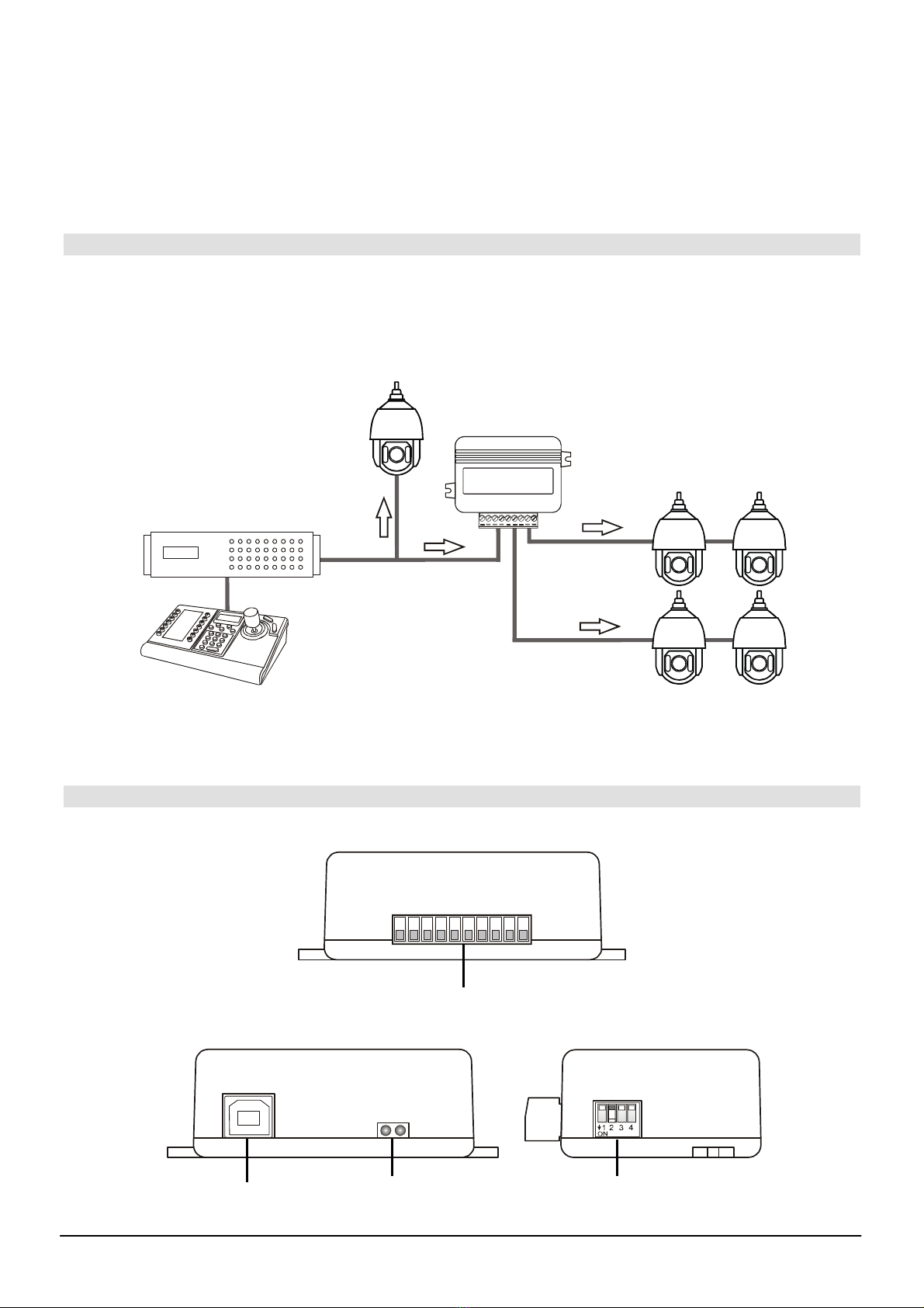
Connection structure
The converter has one input port for Bosch (Biphase / OSRD) and two Pelco output ports, each of which
is freely configurable as Pelco-D or Pelco-P. It is installed between a Bosch control device (PTZ
keyboard, DVR, Video Matrix, Encoder, etc) and other Speed Dome cameras. Can be located anywhere
between control device and PTZ cameras..
PORT 1
Biphase / OSRD
(RS-485)
PORT 3
Bosch
PTZ
keyboard
Pelco Speed Dome
PORT 2
Pelco-D / Pelco-P
Pelco-D / Pelco-P
Bosch
Speed Dome
Bosch->Pelco
Bosch
Video Matrix / DVR
The basic way to connect a Pelco Speed Dome to Bosch CCTV system
Description of configuration and connection elements
110
POWER / COMMUNICATION PORTS
USB LED DIODES DIP SWITCHES
CONV Bosch To Pelco - firmware 0.01.xx
Ewimar Sp. z o.o.
www.ewimar.pl Made in Poland
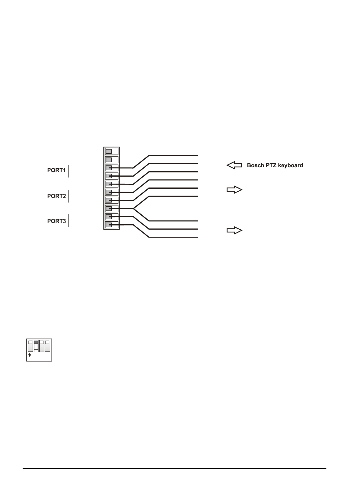
POWER / COMMUNICATION PORTS – Removable terminal containing converter power terminals and
RS-485 / BIPHASE communication ports. The purpose of each port is described below.
LED DIODES.
Red – depending on the settings, informs about translation and sending data to the camera or
informs about corrupted data packets / collisions, coming from the control device.
Green – depending on the settings informs about any data coming from the control device or
about the correct packets only (correct protocol and transmission parameters). Signaling that
the correct packets have been received does not mean that they will be translated, because it
also depends on settings the supported addresses by the converter.
DIP SWITCHES – Designed to switch on termination resistors for ports 1 ~ 3 and to run the converter
firmware update mode.
USB – It is designed to configure settings using the Firmware Upgrader / Configurator and to perform
software updates / changes
Power AC/DC
Power AC/DC
485 - A(+)
110
485 - B(-)
GND
485 - A(+)
485 - B(-)
GND
485 - A(+)
485 - B(-)
}
}
}
Pelco Speed Dome
Pelco Speed Dome
C+
C-
GND
A
B
GND
A
B
GND
POWER - Connect a power source in the range 9 ~ 24V AC / DC - any polarity.
GND – Power Ground communication ports. It is recommended to connect with cameras and keyboards
to avoid damage due to the ground loop effect.
PORT1 – Configurable input port for connecting a PTZ keyboard with Bosch OSRD (RS-485) or Bosch
Biphase. When OSRD is chosen also baudrate adjust is avaiable by Configuration software (by
default: Pelco-D, 9600baud).
PORT2 – Output port do Speed Dome cameras with Pelco protocols.
PORT3 – Output port do Speed Dome cameras with Pelco protocols.
DIP-SW
12 43
ON
Dip switches No 1~3 are designed to turn on termination resistors accordingly for ports
1~3. After set to ON, internal 120Ωresistor is connected between A and B of according
port.
Dip switch No 4 is used to emergency firmware update if during normal update
communication has been lost. This way to repair broken firmware. To activate emergency
update mode set DIP No 4 to ON and restart power supply (reconnect the USB). For
normal operation DIP No 4 must be in OFF position. Emergency update method has been
decribed in manual of the Firmware Upgrader / Configurator.

CONV Bosch To Pelco - firmware 0.01.xx
Ewimar Sp. z o.o.
www.ewimar.pl Made in Poland
Settings and available functions
Configuration of the converter is carried out using the software available at:
www.ewimar.com/soft/configurator.rar - the file contains drivers and operating manuals needed to
run.
Configuration of the converter is done after connecting it to a PC with a standard USB cable. The
converter is detected as another COM port with fast data transmission.
The converter is connected to the software by selecting the COM port (the converter is detected as a
USB serial port) and clicking the "Connect" button.
The "Get user manual" button opens the current User Manual for the firmware version of the converter
in the default web browser. It may contain more detailed information than paper manuals. To open the
manual you need an internet connection and installed PDF browser. Web address to the manual is also
displayed after reading the converter configuration.
The "Get Current Configuration" button displays the current converter configuration settings in the left
panel. The "Command list" button displays a list of commands available for the current firmware version
along with the command's syntax and range of input data.
The right panel displays the command sent to the converter and its response about a changed setting or
an error.
Each command must be entered in full syntax (letters, dashes, etc.) and the allowable range of
data. The x, y characters must be replaced by the appropriate value.
The following parameters are defined in the converter:
1. Protocol type for Port 1: Command „P1-x”.
Selection of communication protocol for the PTZ keyboard: P1-0 = Biphase -D, P1-1 = OSRD.
2. Protocol type for Port 2: Command „P2-x”.
Selection of communication protocol for the Speed Dome: P2-0 – Pelco-D, P2-1 - Pelco-P.
3. Protocol type for Port 3: Command „P3-x”.
Selection of communication protocol for the Speed Dome: P3-0 – Pelco-D, P3-1 - Pelco-P.
4. Baud rate: Command „Bx-y”.
Used to select the baud rate for each ports in the range 1200 – 115200 baud.
The xmeans port number (1-3), ymeans baud rate (0-8). Notice! After set port 2 or 3 to Biphase
the baud rate can’t changed.
Example: To set the speed 9600baud for port 1, enter „B1-3”.
5. PAN speed for FIXED: Command „MP-x”.
Used to set PAN speed movement for Pelco cameras during translation FIXED type commands.
The xcharracter mean speed with range 1-7.
Example: To set speed movement for PAN, enter „MP-4”.
6. TILT speed for FIXED: Command „MT-x”.
Used to set TILT speed movement for Pelco cameras during translation FIXED type commands.
The xcharacter mean speed with range 1-7.
Example: To set speed movement for TILT, enter „MT-4”.
7. Green LED: Command „DG-x”.
Configuration for Green LED operation. DG-0 – Indicates of any data received from on the Port 1,
regardless of the protocol setting or transmission speed.
DG-1 – Indicates of receiving only the correct packets on Port 1.
8. Red LED: Command „DR-x”.
Configuration for Red LED operation. DR-0 – Indicates the translation and sending commands to
Bosch cameras - only if the controlled camera address is configured in the converter.
DR-1 – Indicates wrong packets received on Port 1 - wrong protocol, incorrect transmission
speed or transmission errors due to the use of poor quality cable..
9. Supported camera addresses: Command „CAx-y”.

CONV Bosch To Pelco - firmware 0.01.xx
Ewimar Sp. z o.o.
www.ewimar.pl Made in Poland
The converter contains a camera table, the capacity of which depends on the license entered - by
default 16 for the Standard version and 1for the Lite version. The table should be assigned
camera addresses in the range from 1-254, which will be supported by the converter.
The xcharacter mean the position number in the table, ymean supported camera address (1-
255) entered at that position.
Choose the position number and assign an address to it. Example: To assign camera address
128 to position No 1, enter: CA1-128.
The order of the addresses in the table does not matter if the addresses repeat, only the first one
matters. If „Address Shift” function is active can be used address 1-16383. It allows to control
Pelco cameras in big Bosch CCTV systems. For input addresses above 255 must be assigned
output addresses 1-255 in the Shift fields.
10. Special: Command „Sxxxxxx”.
Execution of a special command, for example entering the license code..
11. Address shift: Command „CSx-y”.
Described in the extended manual downloaded with the " Get user manual " button.
Always active in Lite version, active in Standard version after purchasing the license.
12. Advanced joystick correction: Command „CPx-y” i „CTx-y”.
Described in the extended manual downloaded with the " Get user manual " button.
Always active in Lite version, active in Standard version after purchasing the license.
List of translated commands from the Pelco keyboard
Nr Command from Bosch keyboard Pelco camera function
1 Move Up / Down / Left / Right Move Up / Down / Left / Right
2 Zoom in / Zoom out Zoom + / Zoom -
3 Focus Far / Focus Near Focus Far / Focus Near
4 Iris open / Close Iris Open / Close
5 Call SHOT 1~100 / Set SHOT 1~100 Call Preset 1~100 / Set preset 1~100
6 Aux ON 1 ENTER Start Auto-Scan
7 Aux ON 2 ENTER Auto-Pan
8 Record A (Aux ON 100 ENTER) Record pattern
9 End record A (Aux OFF 100 ENTER) End record pattern
10 Continous Playback A (Aux ON 50 ENTER) Start pattern
11 SET SHOT 101 Set left limit
12 SET SHOT 102 Set Right limit
Fixed-Start-Stop and Fixed-Repetive commands do not contain information about the speed of
movement. During translation to Pelco movement speed always is constant with value set by Firmware
Upgrader / Configurator or by SET/SHOT 98 and 99 as below:
No Command of Bosch keyboard Result
1 SET SHOT 98 Increase PAN movement +1
2 RUN SHOT 98 Decrease PAN movement -1
3 SET SHOT 99 Increase TILT movement +1
4 RUN SHOT 99 Decrease TILT movement -1

CONV Bosch To Pelco - firmware 0.01.xx
Ewimar Sp. z o.o.
www.ewimar.pl Made in Poland
Known problems and their solutions
No control Pelco Speed Dome - the green LED blinks during control, the red LED does not blink
1. Set the green LED to display only valid packets.
2. If the green LED is not blinking, check the connection and transmission parameters.
3. If the green LED is blinking, check if the camera address you want to control is set in the converter.
No control Pelco Speed Dome – the green LED blinks on the control, the red LED blinks from time to time.
1. Check the correct connection between the converter and the keyboard.
2. Check if the RS-485 terminating resistors are included in the keyboard and converter, if the distance
between the converter and the keyboard are over 100m
3. Check the power supply stability of the converter
No control Pelco Speed Dome – green and red LED blinks.
1. Check the correct connection of the cables between the converter and the camera.
2. Check if the Pelco output protocol is suitable for the controlled cameras, check transmission baud rate.
3. Check if the termination is configured following the rules of RS-485.
4. Check the baud rate and camera address settings.
Time to time there is no camera control or the camera rotates continuously and cannot be stopped.
1. Set the red LED to display erroneous packets.
2. If the red LED blinks frequently, transmission is interrupted as a result of incorrect connections or data
collision with another control device.
3. Check if the termination resistors are included in the converter and in the camera.
4. Possible interference from the ground loop effect - a data separator is required.
No LED’s light up when attempting to control.
1. Set the green LED to display all data.
2. If the green LED is blinking, verify the baud rate and protocol settings on PTZ keyboard and in the
converter.
3. If the green LED is not blinking, check the connections between the keyboard and the converter.
4. Check the converter power supply. Restart power - after connecting power supply red diode should blinks
several times.
The device failed to start despite the above tips? Contact Ewimar Sp z o.o. Technical Support.
The converter is a specialized product and to connect and run this product, basic electronic knowledge,
knowledge of communication interfaces and issues related to the installation of CCTV devices are
necessary. The manufacturer is not liable for losses related to the use of the device, failure to operate or
damage caused by the lack of proper knowledge of the user. This manual does not convey general
knowledge, only information applicable to this product.
In the absence of operation or malfunction of the device or any complaint, please contact the
manufacturer immediately.

CONV Bosch To Pelco - firmware 0.01.xx
Ewimar Sp. z o.o.
www.ewimar.pl Made in Poland
DECLARATION OF CONFORMITY
PRODUCT:
PTZ Protocol Converter
MODEL:
CONV Bosch To Pelco
MANUFACTURER:
Ewimar Sp. z o.o.
ul. Konarskiego 84, 01-355 Warszawa
We hereby declare that the above product is approved for work within the EU and is compliant with
essential requirements and other relevant provisions of EMC Directives 2014/30 / EU and 2011/65 / EU -
RoHS directive:
PN-EN 61000-6-3: 2008 / A1: 2012 - Electromagnetic compatibility (EMC) - Part 6-3: General standards -
Emission standard in residential, commercial and slightly industrialized environments
Warsaw 2nd March 2020 r. Ewimar Sp. z o.o.
Manufacturer:
This manual suits for next models
1
Table of contents
Other Ewimar Media Converter manuals


