4.2-10
www.EWSWATER.com office: 702-256-8182 (m-f; 8:30-4:30, pst) fax: 702-256-3744 customerservice@ewswater.com
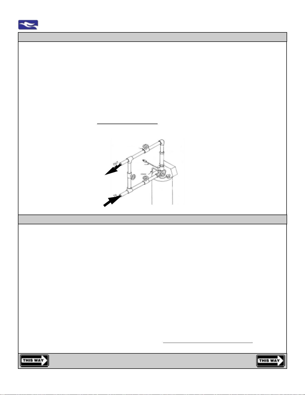
3 - PLUMBING LINE CONNECTIONS:
Check the Following:
Main Water Supply Line, DrainAccess, Electrical Outlet, and Clearances to comlepte the install.
Location of Tank: Unitscanbe installed,almostanywhere.Inside or outside. However, use yourcommonsense.Valves
may be water resistant, not water proof. Protect any system from the elements. Review issues on water flow rates and
pressure, and environmental and water temperature ranges. The tank should have access to the supply water, provide
filteredwater to the home,be located closeto a clean workingdrain, have an electricaloutlet available, andbe connected
according to all local plumbing codes.
Water Temperature Range: Feed water temperature not to exceed 110°F or be allowed to go below 40°F. Protect unit
fromexceeding high temperatures anddirectsunlight, and never allowunit, the drain line andanywater to freeze.
Electrical: Anuninterrupted alternating current (A/C) supplyis required. The systemisideally located within 4-6feetof a
110 volt outletto allow theunit to be pluggedin.A24 volt motor andtransformer is available forlonger electrical runs(use
10-2 regularlampgauge wire). The 24 volttransformermustbe located inside.
Existing Plumbing: Condition of existing plumbing should befreefromlimeandironbuildup.Pipingthatisbuiltupheavily
and clogged with lime and/or iron should be replaced. Problem with iron? Our separate iron filter unit should be installed
aheadof any otherunit. Old galvinizedor combinations ofplumbing materials cancause water issuesand conditions.
Drain Connection: Nominal drain line and drain size on 1035/1054/1354 (non-iron) units should be a minimum of 1/2”.
Anydrainlineexceeding20’inlengthand/orexpectedtoflowover5’abovetheheightofthedrainportrequiresanincrease
indrainlineto3/4”.Install,non-restrictive,check valve in drain line, if drainwaterisexpectedtoflowover5’abovetheheight
ofthe drain port. Never restrictthebackwash drain water flow.Teflon tapeistheonly sealant to be usedonthe drain fitting.
Check Incoming Water Pressure and Flow Rates: A minimum of 35 PSI and 8 GPM for 1035 & 1054 units/12 GPM
for 1354 units is required for backwash valve to operate effectively. Water pressure not to exceed or to surge in excess of
amaximumof65PSIforthesystem.Unsureofpressureorit’sabilitytosurge? Apressurereducingvalve(PRV),orlimiting
pressure to 65 PSI is recommended for this and many other kitchen and bath products in your home.Automatic valve is
ratedfor 100 PSI andthe tank israted for 150 PSI,however the overall systemwith various connections haslimitations to
excessive pressure. Water pressure measuring 65 PSI during the day may surge to over 100 PSI at night when the
automatic backwash occurs.
Install(oftenrequired by code) apressureregulator (PRV) if the waterpressure exceeds or can surgeabove65 PSI.
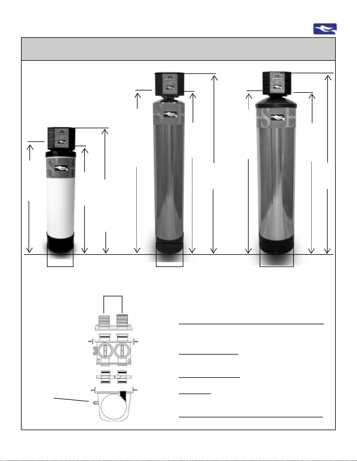
1 -PREPARE FORINSTALLATION:
1) PLACE THE TANK WHERE YOU WANT TO INSTALL THE UNIT.
Make sure the tank is level and on a firm base. Black bases on tanks are glued-on and self-leveling. If necessary, lift tank
andtap thepartofthebasetofloor,inordertolevelunit.Takenoteoftheclearancesnecessarytocompletetheinstallation.
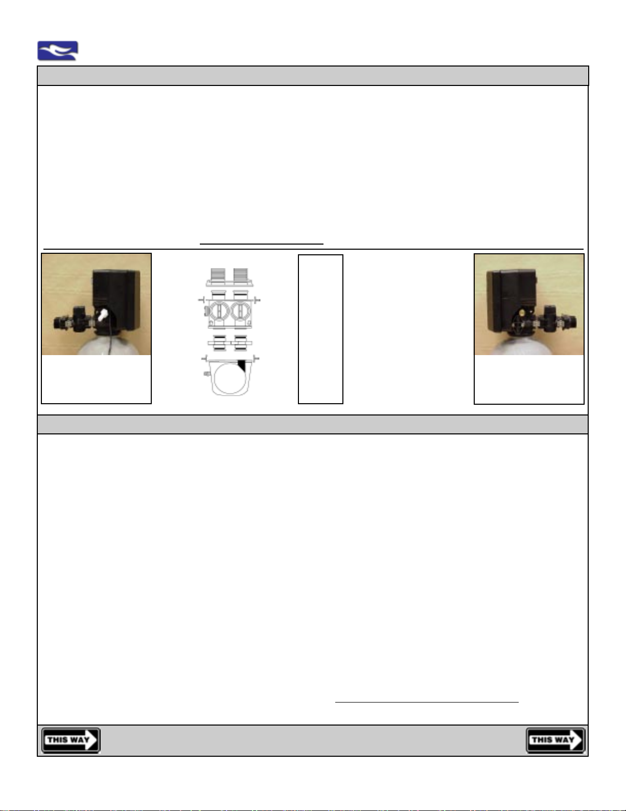
2) CHECKAND TIGHTEN VALVE HEAD ON THETANK.
HandTightenthe Valve Head inaClockwiseDirection.Makesurethestainlesstankcoverorplasticdome(1354units)does
not interfere or cut into the connections.
WARNING:Stainlesscovers are non-functional,if“dinged” in handling, turn togoodside.
3) CONNECT BYPASS VALVEAND MALE YOKE TO VALVE HEAD.
Makesurebypassvalvesarefacingup.Keepbypassvalvelevel(horizontal).Donotput,upordownward,and/orsideways
pressureonbypassvalve,thiswillnot allow nipples and o-rings to seat squarely and completelyandovertimecouldcause
underpressureconnectionfailure.
2 -UNBOX UNIT:CHECK TANKAND VALVEANDLOCATE BYPASSAND MALEYOKE:
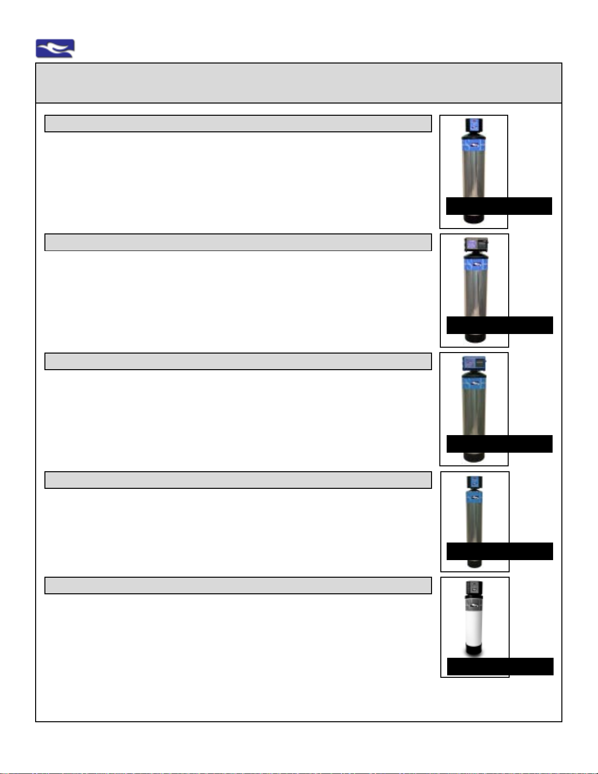
EWS & CWL 1035, 1054, 1354
1) IDENTIFYTHE MAIN WATER SUPPLY.
Do NotAssume. You may have to perform “the old bucket test” to determine where the water is coming from.
Make sure the whole facility is on the line. Some cold water lines (kitchen, island, wet bar sinks, refrigerators, ice
makers)mayhavebeen plumbed separately, if previously plumbed for (salt)softenedwater.Youmayhave to recapture
thoselines by replumbingthat manifold. Or,capture the mainwater supply beforethe bypassed or “looped”away lines,
usuallyfound at, orafter,the main water shut off.However, some plumbingdesigns prevent thisideal installation.Asink
(point of use) filtration unit can be used for that missed location.