EWS FUGAC200 Guide

EWS, Inc. / Environmental Water Systems 4.1-1
www.EWSWATER.com office: 702-256-8182 (m-f; 8:30-4:30, pst) fax: 702-256-3744 customerservice@ewswater.com
Care and Use Manual
Drinking Water Filtration Systems
Two-Stage Undercounter Drinking Water Filtration Units:
FUGAC200, FUGAC250, UU250
Three-Stage Undercounter Drinking Water Filtration Units:
FUGAC300, FUGAC350, UU350
In-Line Filtration Unit:
FUGAC150
To the Consumer:
Retain this Care & Use Manual for Maintenance and Information
You Must Register this Product - It is a Requirement for Warranty
ALL PRODUCT PROUDLY MANUFACTURED AND ASSEMBLED IN THE USA
Information Provided for the Proper Set-Up, Installation and
Start-Up of the following Filtration Systems

EWS, Inc. / Environmental Water Systems
4.1-2
www.EWSWATER.com office: 702-256-8182 (m-f; 8:30-4:30, pst) fax: 702-256-3744 customerservice@ewswater.com
A Special Message to Our Customers,
EWS, Inc. and Environmental Water Systems would like to thank you for your consideration in selecting from our
comprehensivelistofresidentialfiltrationandconditioningproduct.
We recommend that you take the time to read the information that pertains to your product as you begin to use it.
The information in this manual is designed to assist your installer to set-up, install and start-up your system properly.
Inaddition,the information containedinthis manual is designed to provide theconsumer,themostcomprehensive
informationonthis series of product.
Please contact us if you have any questions, comments or additions to the information provided.
Sincerely,
Customer Service at EWS, Inc.
EWS, Inc. and Environmental Water Systems
9101W. SaharaAve., Suite 105-J8
Las Vegas, NV. 89117
Office: 702-256-8182 AvailableMondaythroughFriday, 8:30 - 4:30 PacificStandardTime
Fax: 702-256-3744 DedicatedandAvailable 24/7
E-Mail: customerservice@ewswater.com
Web Site: www.ewswater.com
Installation of the Filtration System - Please Read the Enclosed Information
Please take the time to familiarize yourself with the unit you are about to install. The Table of Contents will point to
specific instructions for the simple step-by-step instructions for;
Installation of a Dispenser/Faucet
Placement or Locating the Water System
Inlet Supply Water Connection
Connection of Tubingfrom Supply and to Dispenser/Faucet
System Start-Up and Operation Procedures
You may need the following for proper installation:
• Teflontape • WorkGloves • Safely Glasses • Knife or scissors
•Adjustable Wrench • Pliers •Screwdriver; straight & phillips • Drill & drill bits
WARNING: Verifythat all components are included withthe unit and were not lost,misplaced, or damaged in shipping
or handling.Any damage in shipping needs to be reported to the shipping company.
WARNING: Do not attempt to install this systemusingdefectiveordamagedcomponents.Checkandinspect, inlet and
outletfittings and any other connectionsonthissystemthat might have been damaged duringshippingandhandling.Check
allthese componentsagainuponinstallationand start-upforanyhidden issues.Allplumbingshouldbedoneinaccordance
with all local plumbing codes. Water Pressure: minimum 25psi, maximum 65psi. Water Temperature Range (cold supply
only): not to exceed 110°F or below 40°F. Electrical (if applicable): an uninterrupted a/c supply, (if applicable): make sure
voltage supply is compatible with your unit prior to install
WARRANTY: Warranty Registration of this product is required to have a warranty.Aproper installation and start-up will
saveyou time, money and hassles, andisalsorequiredfor warranty purposes.Anyissueasa result of improper application,
set-up,installationand/or start-upwillvoid any warranty.

EWS, Inc. / Environmental Water Systems 4.1-3
www.EWSWATER.com office: 702-256-8182 (m-f; 8:30-4:30, pst) fax: 702-256-3744 customerservice@ewswater.com
INSTALLATION SUMMARYAND INDEX
OF YOUR DRINKING WATER FILTRATION SYSTEM
Placement or Locating the Dispenser/Faucet (2 & 3 Stage Units Only) 4
Installation of the Supplied Dispenser/Faucet (2 & 3 Stage Units Only) 5
Dispenser/Faucet Q & A 6
Placement or Locating the Water System 7
Inlet Supply Water Connection
Basic Supplied Connection 8
Preferred Connection 9
Connection of Tubing from Supply and to Dispenser/Faucet 10
System Start-Up and Operation Procedures 11
HOW TO MAINTAIN YOUR SYSTEM
Replacement of Filter Cartridges 12
Replacement of UV Lamp (if applicable) 13
Optional Disinfection Procedure of Empty Unit 13
GENERAL INFORMATION
Water Fitration Systems Included in this Care and Use Manual 14
FILTER REPLACEMENTS AND ORDERING
Filter and UV Lamp Replacements 16
Ordering Filters, UV Lamp Replacements, and Parts 17
TroubleShooting Guide 18
Schematics 20
Warranty 24
Terms and Conditions of Sale 26
Table of Contents

EWS, Inc. / Environmental Water Systems
4.1-4
www.EWSWATER.com office: 702-256-8182 (m-f; 8:30-4:30, pst) fax: 702-256-3744 customerservice@ewswater.com
Step by step instructions to mount and secure the supplied dispenser/faucet
Professional Installation is Strongly Recommended
Note:
Dispenser/Faucet Not Included with In-Line Units. Sold separately, or use existing or other dispenser.
Step 1: Locate Faucet Parts Bag (2 and 3-Stage Units Only)
Parts Included: faucet body with handle, faucet spout with tip, decorative washer, black rubber
washer, white beveled washer, lock washer, hex nut, 1/4” tube insert sleeve,
Included 1/4” plastic compression ferrule, 1/4” compression nut
Optional Part: flat white washer (for use under decorative washer depending on hole/application)
Preferred - Select a standard sink location to mount the faucet.
It is recommended that the faucet be placed in a hole provided on most sinks similar to the ones used for a
sprayer, soap dispenser and/or dishwasher air gap. If the holeorspaceis unavailable, an alternative location
willbe required:MINIMUMHOLE REQUIRED1/2”,MAXIMUM 13/8”
OptionA: On the sink. This option is to drill a new hole into the sink rim itself, if space allows.
Option B: On the countertop next to a sink. This option is to position the faucet spout in the
correct location to drain into the sink. This requires a clearance around the faucet
both above and below the countertop. Use the supplied dispenser as a template or
see the enclosed dispenser schematic and dispenser dimensions.
Prepare to drill the hole using the dispenser as a template.
•Sinks can be made of, but not limited to, stainless steel, copper, porcelain/steel, enamel/cast iron,
man-made surfaces, stone, concrete, and/or materials known or unknown at this time.
•Countertops can be made of, but not limited to, or be a combination of, natural stone, enamel,
porcelain, concrete, wood, metals and/or man-made materials known or unknown at this time.
CAUTION: Please consult with the sink or countertop manufacture, supplier, fabricator, or
installer for proper drilling techniques and methods.
EXTREMECARE MUSTBETAKEN INDRILLINGTHEHOLEFORANYSURFACE.THE SURFACEMATE-
RIALS OF SINKS AND COUNTERTOPS CAN CHIP OR CRACK. THE MANUFACTURER ASSUMES NO
RESPONSIBILITYFORANYDAMAGERESULTINGFROMTHISINSTALLATION.
WARNING: USE SAFETY GLASSES OR OTHER EYE PROTECTION WHEN GRINDING OR
DRILLING TO PREVENT POSSIBLE EYE INJURY DUETO FLYING PARTICLES.
Placement or Locating the Dispenser/Faucet
Follow Steps 2 through 12
Installation of the Supplied Dispenser/Faucet

EWS, Inc. / Environmental Water Systems 4.1-5
www.EWSWATER.com office: 702-256-8182 (m-f; 8:30-4:30, pst) fax: 702-256-3744 customerservice@ewswater.com
Installation of the Supplied Dispenser/Faucet (2 & 3-Stage Units Only)
Below the Surface
Step 5:
Insert white beveled washer, bevel side up to
fit snugly into a (1 3/8”) pre-drilled hole or flat side
up depending on the application
Step 6:
Place lock washer on this white beveled washer
Step 7:
Spin hex nut onto faucet stem and
tighten hex nut and washers into place
Step 8:
Slide 1/4” compression nut (threads up)
onto 1/4” filtered line
Step 9:
Slide 1/4” plastic compression ferrule, long side
down onto filtered water tube. Ferrule will seat into
compression nut
Step 10:
Insert 1/4” tube insert sleeve into 1/4” filtered water line
Step 11:
Insert 1/4” blue (filtered water) tube into faucet stem. Leave
other end available for system interconnection
Step 12:
Thread 1/4” compression nut onto faucet stem and tighten
CAUTION: Do not overtigthen fittings
Above the Surface
Step 2:
Place decorative washer to bottom of faucet body
(optional: place flat white washer under decorative washer)
Step 3:
Place black rubber washer below decorative washer
(or below optional flat white washer)
Step 4:
Place faucet stem through hole and center
Note: Spout pulls out from faucet body and has 2 o-rings at base. Insert completely into bottom of faucet body to prevent
leaking. Spount swivels to direct water. Handle and tip can be removed. Handle can be locked up in open position.
** Other faucets check with specifications. ***Alldimensionsareapproximate.
EnclosedDispenser/Faucet Dimensions***
Height: from deck to top of dispenser 8”
from deck to tip of dispenser 6 1/4”
Reach: from center of dispenser to tip 6”
Hole: minimumrequired 1/2”
maximum 1 3/8”
Go to the Placement or Locating the Water System
Step by step instructions to mount and secure the supplied dispenser/faucet
If using another faucet, please review the instructions included with that product**

EWS, Inc. / Environmental Water Systems
4.1-6
www.EWSWATER.com office: 702-256-8182 (m-f; 8:30-4:30, pst) fax: 702-256-3744 customerservice@ewswater.com
Q: I do not want to drill any extra holes or use a separate dispenser/faucet - what can I do?
A: An alternative to installing and using the dispenser/faucet is to consider a direct connection to your
existing kitchen (cold side) faucet. Connect the supply from the cold water angle stop to feed/inlet side of the
filtration system as directed in this manual. Then connect the filtered/outlet side to the cold feed side of the
kitchen faucet. Special fiitings, that are readily available to the plumbing professional, will be required to fit this
application based on line size and materials used.
WARNING: This is not a preferred method due to a more complicated install, lower flow rates to your
kitchen faucet and most importantly, the possibility of water quality issues as a result of the
aerator at the end of the kitchen faucet not intended for filtered water.
Note: There will be a diminishment in your flow rate to the cold side of the faucet (kitchen faucet
has a flow rate of up to 2.3 gallons per minute and the filtered water is delivered up to 1 gallon
per minute). To get filtered water you must be sure you have the faucet to the cold side only.
This application or option may not be applicable for reverse osmosis systems.
Q: I would like to use another dispenser/faucet?
A: Based on many styles and finishes, a consumer may have another dispenser they would like to use.
No problem, all these items have universal or industry standard fittings, or if not, can be easily adapted to fit.
Note: EWS, Inc. includes a standard chrome, long-reach, lead-free faucet with white handle and tip.
Options: EWS provides the following options to match other items at an additional charge;
Change your white tip and handle to black
Change your faucet to the following finshes; white faucet (with white tip and handle), satin
nickel, polished nickel, polished brass, or oil rubbed bronze (all with black handle and tip).
Inquirewith your local EWS, Inc. distributor, contact an authorized internet distributor orvisitus
on the web (see page 4.1-17 for more details).
Q: Can we connect the filtered water up to other devices?
A: Yes, simply connect by a “T” connection, the filtered water line to any instant hot, chiller, ice-maker,
refrigerator, etc. Regarding flow rate, be mindful of too many (3 or more) connections and/or any length
limitations in excess of 15 feet to any item that may create issues with delivery rates. See our Point of Entry,
Whole HomeAppliances to filter all the fixtures within the home.
Note: Spout pulls out from faucet body and has 2 o-rings at base. Insert completely into bottom of faucet
body to prevent leaking. Spount swivels to direct water. Handle and tip can be removed. Handle
can be locked up in open position.
Other faucets check with specifications.
All dimensions are approximate.
Dispenser/Faucet Q & A

EWS, Inc. / Environmental Water Systems 4.1-7
www.EWSWATER.com office: 702-256-8182 (m-f; 8:30-4:30, pst) fax: 702-256-3744 customerservice@ewswater.com
Placement or Locating the Water System
Simply place the water system on a level floor, cabinet bottom or horizontal surface.
Always assume for enough space and tubing to remove, move and/or adjust
for filter replacement and maintenance.
If mounting the system to a wall, cabinet side or other vertical surface,
Please see the following;
Step 1: All filter cartridges for the system are preinstalled. If the unit is installed in a permanent
hanging position, a minimum clearance of 2” will be required to allow filter replacement.
Step 2: Mark pilot holes using the bracket as a template.
Step 3: Using a drill bit or punch, drill a hole or punch as a starter hole to catch the mounting
screws.
WARNING: ALTERNATIVE FASTENING METHOD MAY BE REQUIRED FOR PLASTER BOARD,
PARTICLEBOARDOR SIMILAR MATERIALINSTALLATION. USE SAFETYGLASSES
OR OTHER EYE PROTECTION TOPREVENT POSSIBLE EYE INJURY DUE TO
FLYING PARTICLES.
Step 4: Set mounting screws (provided) with screw driver. Leave a 1/4” gap between the screw
head and mounting surface to allow the bracket to slide on easily.
Step 5: Slide the bracket over the screws and hang the unit. Make sure unit is level.
Now make the connections of tubing to/from the system.
Go to the Inlet Supply Water Connection
strictly for illustration purposes only
Kitchen Faucet Dispenser/Faucet
of filtered water
Outlet
Filtered Water to
Dispenser/Faucet Inlet from
Cold Inlet/Supply
Connection
(angle stop not
shown)
Mounted to Wall
(option shown) or
Placed on level floor
Helpful Hint:
Find the enclosed Spanner Wrench that
came with the unit and place it on top of
the bracket.
Whenfinished, rollup thisService Guide
and place on top with wrench.
Take a note of the Model # and WQA
Serial # for the required warranty regis-
tration of this unit.
This Service Guide and the wrench will
come in very handy when it’s time for
filter replacement.

EWS, Inc. / Environmental Water Systems
4.1-8
www.EWSWATER.com office: 702-256-8182 (m-f; 8:30-4:30, pst) fax: 702-256-3744 customerservice@ewswater.com
Instructions from the bag containing the supplied saddle tapping valve, if applicable
Step 1: From parts bag locate: saddle tapping valve and 4’ of 1/4” tubing, color coded: red or orange (supply line to unit).
Basic Inlet Supply Water Connection **
CAUTION:Do not turnvalvehandlebefore or while installingthe“saddletappingvalve”.
Make sure the piercing lance does not protrude beyond the rubber gasket. Failure to do this
may result in damage to the piercing needle.
NOTE: For Copper Pipe - go directly to #4.
For Steel or Brass Pipe - follow A, B, C below, then go to #4
A: Drill a 3/16” hole in pipe. Use a hand drill to avoid shock hazard.
B: Turn handle to expose lance beyond the rubber gasket no more than 3/16”.
C: Place body of valve over hole so the lance fits into the hole
Professional Installation Using a Preferred Connection is Strongly Recommended
**Thisunit is supplied with a saddle tappingvalve and should be considered a basic connection for copper,steel or brass
3/8” to 1/2” O.D. pipe prior to the angle stop shut-off of the cold water line to the kitchen faucet. This should be considered
a “do-it-yourself” connection which is not applicable in many situations and may not meet local codes.
Aqualifiedplumber should choose to make theinlet supply water connection by amorepreferred method.
Step 7: Be sure the packing nut is tight, then turn the handle of the saddle tapping valve clockwise
until it is firmly seated. NOTE: For Copper Pipe - the pipe is now pierced.
HINT: Back theend of the piercinglance out, turning thehandle counter-clockwise. Then re-insertby turning the handle
of the saddle tapping valve clockwise until it is again firmly seated. This will clear any possible debris that can
blockpiercinglanceand water flow.
Step 8: Turnthe handle counter-clockwise toopenthe valve for water supply.Keep main line shutoffand proceed with
the remainder of the installation and start-up.
Step 6: Connect the 1/4” plastic tubing to the saddle tapping
valveby following these instructions:
A: Slide 1/4” compression nut over plastic tubing with threads toward the
saddle tapping valve.
B: Slide 1/4” plastic ferrule over plastic tubing with long tapered side
toward saddle tapping valve.
C: Place 1/4” brass insert sleeve into the end of the 1/4” or orange/red
plastic tubing.
D: Insertorange/redtubingintosaddletappingvalve.Leaveotherend
available for system interconnection
E: Tighten compression nut onto saddle tapping valve.
Step 4: Looselyassemblesaddletappingvalve on pipe
A: For all 3/8 O.D. pipe, use side of bracket with side projections
toward or against pipe to prevent distortion of tubing.
B: For all 1/2 O.D. pipe, use “V” side of bracket with that notch
toward or against pipe.
Step 5: Tighten screws evenly. Make sure brackets are parallel,
thentighten firmly until the valveis not moving on the pipe.
CAUTION:Do not over tighten fittings.
Step 2: Locate cold water line that feeds your existing faucet. Determine if there is enough
spaceto install the saddletapping valve on the hard line between the wall and the angle
stop.
CAUTION:USE ONLYCOLD WATERLINE.NOTINTENDEDFORSUPPLYBYHOT
WATER.
Step 3: Shut off the main water supply to the house and open the faucet to relieve water
pressure in the hard pipe. NOTE: Shutting the angle stop only, still leaves water in that pipe.
Shut the main supply.
angle
stop
drain
and
trap
supply
tube
to
filtration
unit
saddle
tapping
valve
pipe for
install
and
clearance
from wall
wall
cold
supply
to
kitchen
faucet
CAUTION:
Donotover
tightenfittings.

EWS, Inc. / Environmental Water Systems 4.1-9
www.EWSWATER.com office: 702-256-8182 (m-f; 8:30-4:30, pst) fax: 702-256-3744 customerservice@ewswater.com
***EWS,Inc.cannotanticipateall the different locations, applications and materials used by your builder and/
orplumbing contractorregardingyour household orsinkpiping, therefore weoffera generic andcommonfitting
withproper instructions.Aqualifiedplumber,plumbingsupplylocation,orhardwarestorewillhavenoproblem
withalternative parts and advice necessary to installyour unit.
A more preferred method to connect the inlet supply line is to shut off
thewatermainandreplacetheentireanglestop.Thiswillhaveacon-
nectionfrom the house main water line, a connection to the cold water
side to the kitchen sink faucet and a much better connection for the
inletsupplyto the filtration unit. This willprovideone fitting with a shut
off to the kitchen faucet and a shut off to the filtration system. The
replacementof the angle stopisabetterplumbing connection and any
number of fittings can be used for the correct application under any
circumstances.
Examplesofcommonconnections and fittings available:
• OPTIONS:
1/2” IPS x 3/8” compression x 1/4” compression
3-wayangle stop
• OPTIONS:
1/2” compression x 3/8” compression x 1/4” compression
3-wayangle stop
Note:
Be sure one outlet is 1/4” compression
forthewater filter 1/4” inlet/supply tubing
Preferred Inlet Supply Water Connection - All Applications
The Preferred Inlet Supply Water Connection is Applicable in All Applications and Codes
Replace the Angle Stop with a Proper 3-Way Fitting:
There are a number of options to properly install any one of these drinking water filtration systems.
Identify the cold water supply line and then you will need to know;
•Size or O.D. diameter of pipe or tubing
•Pipe material (hard or soft copper, steel, brass, stainless, PVC, plastic, etc...)
•The existing angle stop or fitting will assist in determining the proper 3-way angle stop or fitting needed for
yourspecificapplication
Professional Installation Using a Preferred Connection is Strongly Recommended
Aqualified plumber should choose to connect the inlet supply water supply by a more preferred connection. ***
Properinstallationis dependent on your specific applicationand the concept of proper installationisuniversal.
Locate the supply , shut off your main water supply, install the proper connections
andfollow the remaining instructions in this manual.
drain
and
trap main water
supply pipe
cold water
supply pipe
to kitchen
faucet
Example:
new 3-way
angle stop or
fitting
kitchen faucet supply
connection
1/4” filtration
unit supply
connection
water flow
shut
off
wall
Go to the Connections of Tubing to and from System

EWS, Inc. / Environmental Water Systems
4.1-10
www.EWSWATER.com office: 702-256-8182 (m-f; 8:30-4:30, pst) fax: 702-256-3744 customerservice@ewswater.com
Step 1: Before Making the Connections - Remove Colored Vinyl Plugs Correctly
This system may have come with sample plugs. Please remove before installation.
WARNING: NEVERATTEMPT TO REMOVETUBING OR SAMPLE PLUGS BY JUST PULLING.
Follow simple instructions illustrated below to remove properly.
INSPECT: Inspect the fitting for any damage from shipping, handling and/or delivery. STOP, if collet
is damaged in any way; call, fax or e-mail customer service for a replacement fitting.
Step 2: Making the Connections from Inlet/Supply Connection to Unit
and from Unit to Faucet/Dispenser
Firmly insert the tubing completely into the fitting.
You may feel a resistance at the o-rings when you insert the tubing.
Step 2a: Connect the orange/red tubing from the installed Inlet/Supply Connection to the location on
the unit labeled “FEED” (into “Prefilter” housing for all 2-Stage Units, “Sediment” housing for
all 3-Stage Units, or at “Inlet” for Single-Stage, In-Line Units). This is the raw supply water into
the system. Insert and press the tubing firmly and completely into the fitting.
Step 2b: Connect the blue tubing from the installed Dispenser/Faucet to the location on the unit
labeled “FAUCET” (out of “Postfilter” housing for all Units or at “Output” for Single-Stage, In-
Line Units). This is the filtered water line. Insert and press the tubing firmly and completely
intothefitting.
NeverPullTubeOutTo
Remove
Push Collet In To
Release
To Insert,PressTubingIn
FirmlyandCompletely
Connection of Tubing from Supply and to Dispenser/Faucet
CAUTION: Always leave the tubing provided to allow lifting the unit for filter replacement and maintenance.
Make sure tubing has gentle curves. Roll and secure as needed. Do not bend or kink tubing.
Wedo notrecommendshorteningthetubing,however,Ifneeded,atend,cuttubestraightanddo
not flatten.Avoid any tubing contact to hot water lines
WARNING: NEVERATTEMPTTOREMOVE TUBING BYJUSTPULLING.
Follow simple instructions illustrated above to remove properly.
INSPECT: Upon installation, inspect the connection and give the tubing a gentle “tug” to insure
proper connection and integrity of the fitting.
Inspect the fitting for any damage from shipping, handling, delivery, and/or installation.
STOP, if collet is damaged in any way; call, fax or e-mail customer service for a replacement
fitting.
To Test Integrity of Fitting,
Givea Gentle “Tug”To
InsureProperConnection
SeeAll
Cautions,Warnings and
Inspections
Go to the System Start-Up and Operation Procedures

EWS, Inc. / Environmental Water Systems 4.1-11
www.EWSWATER.com office: 702-256-8182 (m-f; 8:30-4:30, pst) fax: 702-256-3744 customerservice@ewswater.com
A proper start-up insures the system is without issues. If anything is discovered, this is the time to
discover it and correct any problems or questions that arise.
Lack of any, or a proper, start-up will void the warranty.
Step 1: For UV Option Only
Connect UV lamp cord and plug in transformer unit to typical 110v electric outlet. (UU250, UU350 only)
NOTE: Electrical outlet must be dedicated and unswitched. Be aware of any GFI outlets and the need
to reset. Surge supression highly recommended.
Step 2: Pull up and lock dispenser/faucet handle (if using another type of dispenser - put into open position).
This will allow water to flow in the open position. Turn off water supply to other devices. Do not make this water
available to any ice-makers, refrigerators or any other devices until the system is completely flushed and
running clear.
Step 3: Slowly - Turn on or open any main water supply which was shut off earlier.
Step 4: Open or make sure there is inlet water supply to the system. Water will begin to flow from dispenser/
faucet. Initially it may sputter until it reaches full flow. Allow system to run steadily for approximately 2 minutes or
more, if needed. This will wash all carbon fines and air from the system. End this flushing of the system once
water runs clear. System is now available to use as normal. Open water supply to other devices, if applicable.
Leave Spanner Wrench that came with unit and this Service Guide on top of unit bracket to assist consumer.
NOTE: If you draw your water into a glass and it appears to be cloudy, it’s only air and nothing bad. Let
the glass sit and watch the air rise and dissipate. The filter cartridges used are full bed depth. The
carbon (GAC) cartridges have a great deal of surface area. With usage, it may take 24-48 hours
for this to correct itself.
Step 5:
Inspect for leaks at all connections, fittings and/or housings. If a problem exists, please shut off water supply to
the system and consider the following solutions;
•Plumbing connections at the inlet/supply connection, saddle tapping valve, or angle stop.
Please review these plumbing procedures and correct.
•Plumbing connections to dispenser/faucet and any other fixtures or cross-connections. Please review
and correct.
•Inspect for leaks at all unit connections such as connections between housings, UV housing and
connections (if applicable), cartridge housings. Report any issues for assistence or needed part(s).
•Inspect for leaks at the labeled “FEED” and “FAUCET” connections between the supplied tubing and
the quick connect fittings. To insure proper connection, give a light “tug” (not a hard pull) on tubing to
check the grip on all fittings.
If any damage was identified in shipping or handling. You’ll need to make a claim with the shipper, as indicated on our
Packing Materials, our Packing Slip and the published General Terms and Standard Conditions of Sale.
If you have identified a problem, please contact our offices. The Best Way; go to www.ewswater.com, click button “Contact
Us” and click link to “Customer Service and Help”, fill out the form and help will be on the way. Let us know if we can offer
advice on a plumbing issue that may not be related to the actual unit, or a question or issue that may be unit related. If in need
of a part under warranty we can readily send it. Parts (original only) needed out of warranty can be obtained through your
contractor, local distribution or at www.waterontheweb.com.
WARNING: Maximum pressure is 65 PSI. Pressure unregulated can surge or exceed the maximum rating on this and
many items in the home. High pressure creates a water hammer or banging pipes. It’s also the reason to use stainless hoses
for washer machine connections and not the rubber. A pressure reducing valve (PRV) at your main water service line (if not
code) is greatly recommended by many manufacturers’ of many different household items, plumbing products and appli-
ances and must be checked annually. A point of use (sink location) pressure limiting valve is also available.
System Start-Up and Operation Procedures
Finished, Go To Required Product Registration
EWS, Inc. / Environmental Water Systems
4.1-12
www.EWSWATER.com office: 702-256-8182 (m-f; 8:30-4:30, pst) fax: 702-256-3744 customerservice@ewswater.com
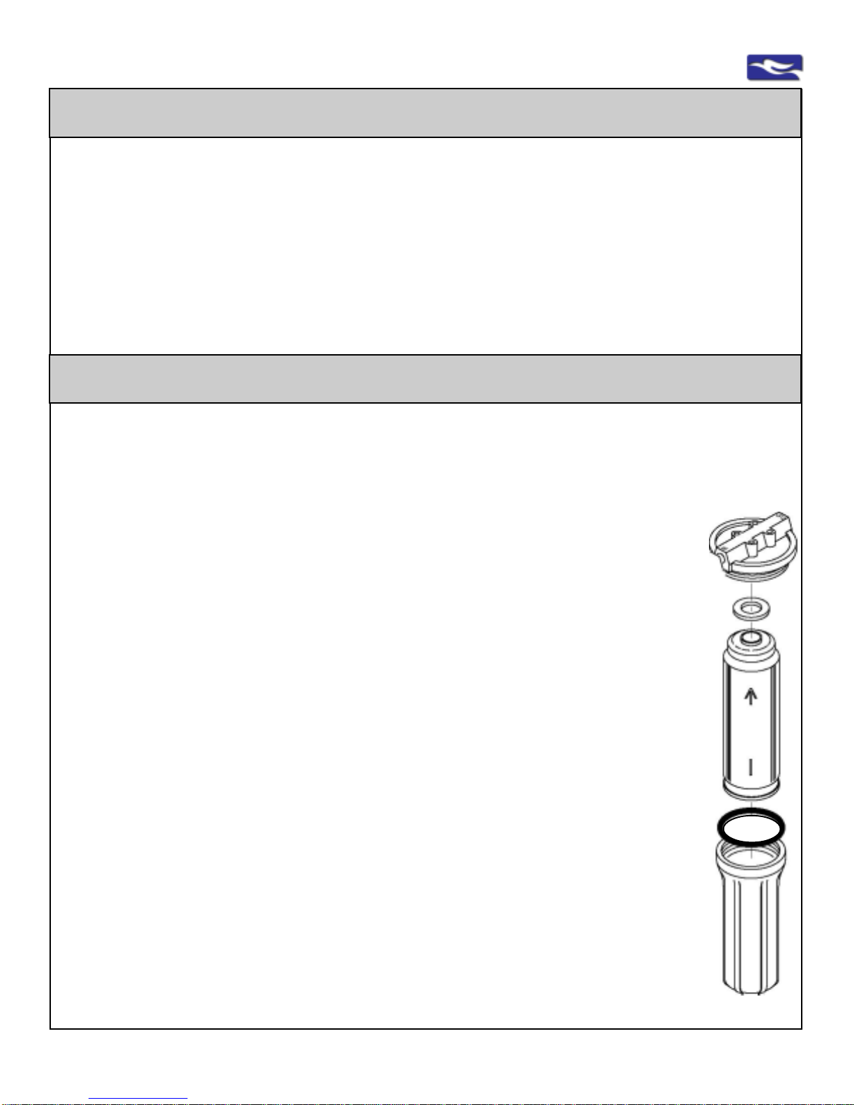
Step 1:
Close inlet water supply to the system.
Step 2:
Open dispenser/faucet. Lock handle in the up position and/or allow water to
flow (water flow should stop in a short time) and keep open to relieve pressure.
CAUTION:
WATER WILL BE PRESENT WHEN FILTERS ARE CHANGED.
A pan, towel, etc. should be placed under the housings to catch any water.
Step 3:
Using your spanner wrench, turn housing (which contains the filter cartridge)
counterclockwise to loosen. Remove housing.
Step 4:
Remove filter and dispose.
NOTE:
See optional disinfection procedure of empty unit before replacing any filters or
UV lamp (if applicable)
Step 5:
Insert new filter(s), replace and tighten housing by turning clockwise.
CAUTION:
The GAC Postfilter (GAC-00 for units FUGAC200, FUGAC300) has a gasket
that must be at the top of the filter to be replaced correctly. All other filters do
not have a top or bottom and can be inserted either way.
CAUTION:
Inspect O-Ring for housing base. Make sure it is clean, free of any debris and
not damaged or kinked. Make sure it is correctly seated into the channel
inside the housing before replacement.
Step 6: FOLLOW SYSTEM START-UP AND OPERATION PROCEDURES
AND FOLLOW PROPER TUBING CONNECTION INFORMATION
Replacement of Filter Cartridges
Familiarize yourself with the system, its’ replacement filters and maintenance.
To Register, take note of the Model # and WQASerial # found on the unit’s bracket,
Understand your system’s capabilities, put the enclosed Spanner Wrench and this Service
Guide on top of the unit bracket,
See your options in water treatment, for you , your family and your home by EWS, Inc.
Register Your System
our confidential data base will remind you to replace your filters, use our enclosed form
which you can fax or mail to our offices, or register on-line at www.ewswater.com
Register this Product - It is a Requirement for Warranty
It is recommended that filters be changed at least annually or more frequently based on usage and
local water conditions. The quantity and quality of the water processed effects the life of the filters.
Housing to
be removed
Upper
Housing
to Bracket
Housing
O-Ring
GAC-00
PostFilter
(ONLY)
Gasket
Faces Up
all other
cartridges
can go in
either
direction

EWS, Inc. / Environmental Water Systems 4.1-13
www.EWSWATER.com office: 702-256-8182 (m-f; 8:30-4:30, pst) fax: 702-256-3744 customerservice@ewswater.com
Optional Disinfection Procedure of Empty Unit
Step 1:
Unplug the transformer. Then disconnect the UV lamp cord.
NOTE:
•Two-Stage Units - UV module is set between the filter housings.
•Three-Stage Units - UV module is set on top of bracket (easier access)
Step 2:
Pull firmly on the UV lamp tail only to remove the lamp. Do Not remove
cap at top of UV Module
Two-Stage Units only: Snap the UV module from the bracket clips to
gain access for lamp removal. Do not disconnect any fittings.
Step 3:
Insert and firmly press new UV lamp into the top of the cap.
Reconnect UV lamp cord.
Two-Stage Units only: Thread UV lamp cord through bracket hole and
then snap the UV module back into the bracket clips.
Step 4:
Reconnect UV lamp cord. Plug in unit transformer.
WARNING:
DO NOT DISCONNECT UV MODULE FROM THE FACTORY CON-
NECTIONSAND DO NOT OPEN UV CAP FROM UV MODULE FOR
TYPICALUVLAMPREPLACEMENT.
Step 1: Follow Steps 1 through 4: Replacement of Filter Cartridges. Empty all housings of their filters.
Step 2: Using chlorine bleach, measure 1/2 cup and pour into first housing base (sideoftheunitlabeled “FEED”
into“Prefilter”housingforall2-StageUnits,“Sediment”housingfor all3-StageUnits).
Step 3: Replaceall empty housings andtighten.Take note of the housing O-Ring.
Closedispenser/faucet to prevent water flow.
Step 4: Slowly Open water inlet valve and allow system to completely fill. Let water sit in system for at least 5 minutes
(leavingit for a longer time willnot hurt).
Step 5: Open dispenser/faucet and let the water run for at least 5 minutes.
WARNING:DO NOTUSETHIS WATER.
Step 6: Now the system, tubing, faucet, and all connections should be disinfected. Follow steps for Replacement
ofFilterCartridges and Replacing UV Lamp (ifapplicable)and prior to Step#5, wipeawayany residual found in
housings or around unit to totally clean this system prior to new filter and UV replacement.
FollowSystemStart-Up and Operation.Always follow proper tubing connection information.
SCHEMATICFORILLUSTRATION
PURPOSES
1-FullyAssembledUVModule
2- UV ModuleHousing
3-UVCapwith Quartz Glass Sleeve
4-UVLampwithLampCord
1
Annual Replacement of UV Lamp (if applicable)
4
3
2
NOTE:
All containers, surfaces and items exposed to water can accumulate a clear or discolored film which may also be
slippery or slimey to the touch. This is a bio-film that is non-pathenogenic and usually of no harm.
This film is most commonly a nuisance and is readily wiped off. It is this reason we suggest a simple
cleaningprocedureprior to returning new filterstothe filtration system.
This procedure maybe performed atany time whenchanging filters
or after extended periods of inactivity of the system.
EWS, Inc. / Environmental Water Systems
4.1-14
www.EWSWATER.com office: 702-256-8182 (m-f; 8:30-4:30, pst) fax: 702-256-3744 customerservice@ewswater.com
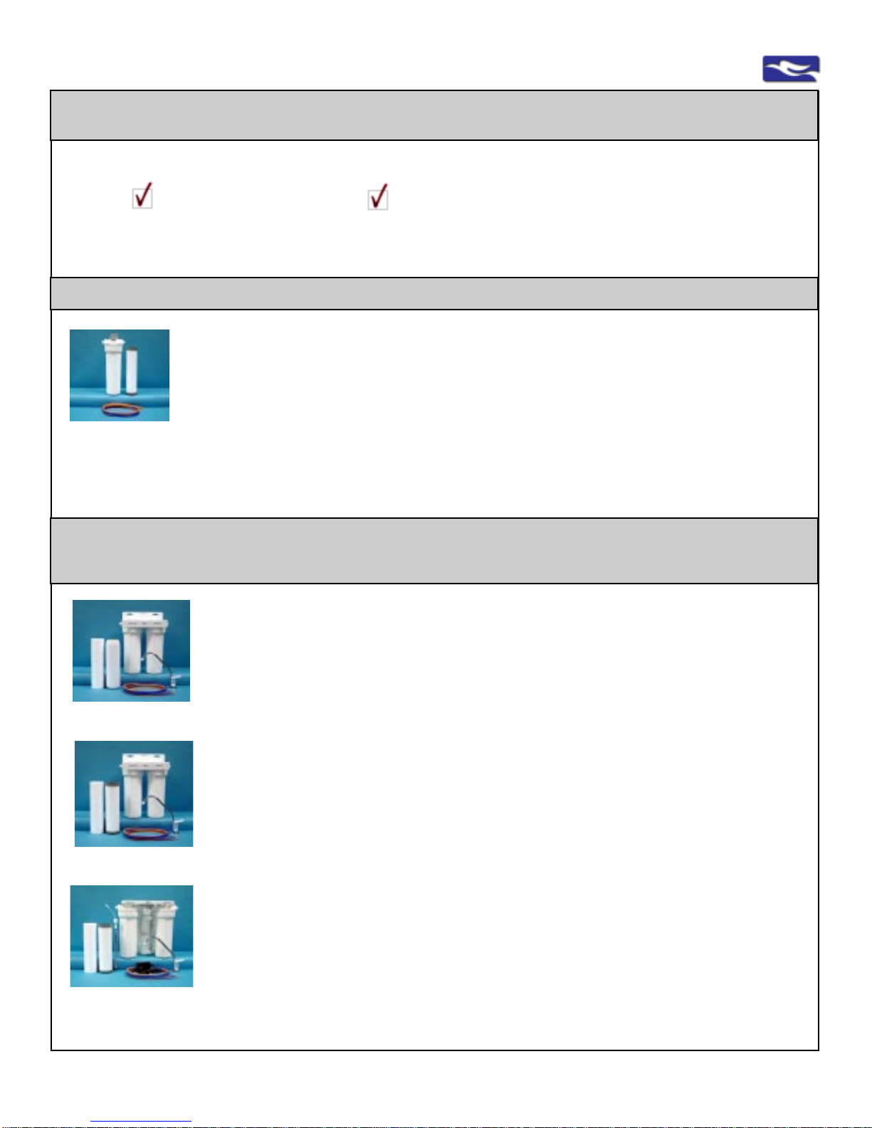
Model No: FUGAC150
Improves taste, clarity and odor by removing chlorine and other volatile organic compounds. The
upgraded filter also safeguards against lead and cysts (giardia and cryptosporidium). Meets or
complies with NSF Standard 53.
Easy to Reference Filter Replacement Code: 7
In-Line, Single-Stage, Limited Usage, Point of Use Filtration Units
ForProperInstallation,Informationand Maintenance- IdentifyyourFiltrationSystem
check the unit check replacements for easy future reference
Water Fitration Systems Included in this Care and Use Manual
Model No: FUGAC200 - Good
Improvestaste, clarityandodor by removingchlorineand other volatileorganiccompounds. The 5-
micronpre-sedimentfilterservestoremove suspendedmatter,dirt,rustandsedimentand improves
performanceofother filters. Meets or complies with NSF Standard42.
Easy to Reference Filter Replacement Codes - the Set Includes: 1, 6
Model No: FUGAC250 - Better
Improvestaste, clarity and odor by removing chlorine and other volatile organic compounds. The
upgradedfilter alsosafeguardsagainstlead and cysts(giardiaandcryptosporidium). The5-micron
pre-sediment filter serves to remove suspended matter, dirt, rust and sediment and improves
performanceofother filters. Meets or complies with NSF Standard53.
Easy to Reference Filter Replacement Codes - the Set Includes: 1, 7
Model No: UU250 - Best
Our best selling unit for sink filtration since1987
Thisunitimproves,removesandsafeguardslikeabovemodelFUGAC250.TheadditionalUVmodule
protects against bacterial, viral, E-coli and other microorganisms and is tested 99.9% effective.
The5-micronpre-sediment filter serves to remove suspendedmatter,dirt, rustandsediment and
improvesperformanceof other filters. Meetsor complieswithNSF Standards53 and 55.
Easy to Reference Filter Replacement Codes - the Set Includes: 1, 7, 16
Undercounter Drinking Water Filtration and UV Units
Standard Two Stage Undercounter Drinking Water Systems
Note: Dispenser/FaucetNot Included with In-Line Units.Soldseparately,or use existing or otherdispenser.

EWS, Inc. / Environmental Water Systems 4.1-15
www.EWSWATER.com office: 702-256-8182 (m-f; 8:30-4:30, pst) fax: 702-256-3744 customerservice@ewswater.com
NOTE: All completely assembled units include the following standard features:
Two and Three Stage Drinking Water Systems include: White 10" housing with filtration cartridges, spanner wrench to open
housings for easy filter replacement, chrome, lead-free faucet with white trim for dispensing water, self-piercing saddle tapping
valve for water line connection with shut-off valve (see service guide for your correct application), all necessary tubing (color coded)
to make proper connections, simple to use mounting bracket, UV lamp and setup (UV unit only) and complete service guide with
installation and use instructions.
In-Line Units are completely assembled units that include the following standard features: White 10" housing with filtration
cartridges,mounting bracket, spanner wrench to open housings for easy filter replacement, saddle tapping valve, tubing and
complete service guide with use instructions.
Undercounter Drinking Water Filtration and UV Units
Model No: FUGAC300
Improvestaste, clarity and odor by removing chlorine and other volatile organic compounds. The
5-micron pre-sediment filter serves to remove suspended matter, dirt, rust and sediment and
improvesperformanceofother filters.The20-micronpre-filteris addedforheaviersedimentand/or
particulate water applications. Meets or complies with NSF Standard 42.
Easy to Reference Filter Replacement Codes - the Set Includes: 1, 2, 6
Model No: FUGAC350
Improvestaste,clarityandodorbyremoving chlorine and other volatile organic compounds. The
upgradedfilteralsosafeguards againstleadand cysts(giardiaand cryptosporidium).The5-micron
pre-sediment filter serves to remove suspended matter, dirt, rust and sediment and improves
performanceofotherfilters.The20-micronpre-filterisaddedforheaviersedimentand/or particulate
water applications. Meets or complies with NSF Standard 53.
Easy to Reference Filter Replacement Codes - the Set Includes: 1, 2, 7
Model No: UU350
This unit improves, removes and safeguards like above model FUGAC350. The additional UV
module protects against bacterial, viral, E-coli and other microorganisms and is tested 99.9%
effective.The5-micronpre-sedimentfilterservestoremovesuspendedmatter,dirt,rustandsediment
andimprovesperformanceofother filters. The 20-micron pre-filter is added for heavier sediment
and/or particulate water applications. Meets or complies with NSF Standards 53 and 55.
Easy to Reference Filter Replacement Codes - the Set Includes: 1, 2, 7, 16
Three Stage Units for Heavier Sediment and/or Particulate Applications
Filter Replacements and How to Order
For more information on the entire product line
from sink to whole home, visit us on the web
Register this Product - It is a Requirement for Warranty
Visit www.ewswater.com, Click on Customer Care and then
Click for the “Product Registration” link
EWS, Inc. will keep this information confidential and will offer you reminders to replace your filters and offer
you updates on water issues and concerns

EWS, Inc. / Environmental Water Systems
4.1-16
www.EWSWATER.com office: 702-256-8182 (m-f; 8:30-4:30, pst) fax: 702-256-3744 customerservice@ewswater.com
Filter and UV Lamp Replacements
Easy Reference: Filter Code No: 1 Replace: UP TO A YEAR*
Model No: PRESED-05 Pre-Sediment Filter (5-micron)
5-MicronPrefilter isapure polypropylenefull-beddepth filter withexceptionaldirt holdingcapability.
Theremovalofany dirt,silt,rustorsuspended matterprotectstheremainingcartridges andextends
theperformance of other filters. Meets FDA requirements for food and beverage contact.
In Use: All 2- and 3-Stage and In-Line Sediment Units :
FUGAC200, FUGAC250, FUGAC300, FUGAC350, UU250, UU350
Easy Reference: Filter Code No: 2 Replace: UP TO A YEAR*
Model No: PRESED-20 Pre-Sediment Filter (20-micron)
20-MicronPrefilter is a pleatedfilterwithexceptionaldirt holding capability.Theremovalofany dirt,
silt, rust or suspended matter protects the remaining cartridges and extends the performance of
other filters and is used in very particulate water conditions. Meets or complies with all FDA
requirementsfor food andbeveragecontact.
In Use: FUGAC300, FUGAC350, UU350 (all 3-stage units only)
For all removal capacities, test results and compliances.
Visit www.ewswater.com
*Replacement of all filters are based on local water conditions and usage.
UV lamp replacement annually (or, as needed within the year)
Easy Reference: Filter Code No: 16 Replace: ANNUALLY*
Model No: UV-LAMP (lamp only) UV Lamp - UV Bacteria-Kill Units
UV Unit contains a 6 Watt UV lamp that effectively kills bacteria (>99%).A316 Bonded Stainless
Steel Interior enhances killpowerbyreflecting UV light and eliminatesdegradationofpolypropylene
housing. Due to advanced design, water is spun through the module to eliminate shadowing and
shadingwhichadditionallymaximizeskillpower.UV Module meets or complies with NSF Standard
55.
In Use: UU250, UU350
Easy Reference: Filter Code No: 7 Replace: UP TO A YEAR*
Model No: GACB-50 Carbon Block 1-Micron Postfilter
Filterisanupgraded postfilter designed for effective reduction of taste, clarityandodorproblems
such as Chlorine and VOC's. In addition, the filter reduces Lead and Cysts such as Giardia and
Cryptosporidium.Cartridgesaredesigned to allow water to pass through entire carbonbedto
allow maximum adsorption. Meets or complies with NSF Standard 53.
In Use: FUGAC150(in-line), FUGAC250, FUGAC350, UU250, UU350
Easy Reference: Filter Code No: 6 Replace: UP TO A YEAR*
Model No: GAC-00 Granular Activated Carbon (GAC) Postfilter
Filteris designed for effective reduction oftaste, clarity and odor problems suchas Chlorine and
VOC's.Cartridgesare designed to allow water topass through entire carbon bed toallow
maximum adsorption. Meets or complies with NSF Standard 42.
In Use: FUGAC200, FUGAC300

EWS, Inc. / Environmental Water Systems 4.1-17
www.EWSWATER.com office: 702-256-8182 (m-f; 8:30-4:30, pst) fax: 702-256-3744 customerservice@ewswater.com
Thereare severalwaysto obtainandorder filterreplacementsfor yourunit.
Contact;
... yourbuilder,plumbing contractorand/oryourinstallerthatprovided theproduct...,
... thekitchen& bathshowroom,distributor,and/orretailerwhere youpurchasedtheproduct...,
... orusethe internetin thefollowingmanner...,
Ordering Filters, UV Lamp Replacements, and Parts
The most convenient way to purchase the correct filters for your unit may be
to visit an authorized web distributor such as www.waterontheweb.com
Followthese easyinstructionsto obtainthecorrect filtersforyour system;
1......... Go to Filters & Parts,
2......... FindSink Units,
3......... FindFilter CartridgeReplacement
4......... Identifytheunityouownandusethescrolldownmenutoenteryourmodel#,(for
exampleUU250) andClickGo
5......... At thebluehighlightedTab forFilterReplacement youwillsee yourcomplete
setoffiltersforyourparticular unit.Nowjust followthesecure storeinstructions
tocomplete thepurchaseand you’redone.
To orderneeded partsfrom thesameauthorized internetdistributor;
1......... Go to Filters & Parts,
2......... FindSink Units,
3......... FindParts Replacement
4......... Eitherenter yourpart #andpress goor scrolldownthrough theparts listing
5......... Clickonthe “Order”buttonto orderapart (returnto thispageif youneedmore
items)foryour particularunit. Oncecomplete,justfollow thesecurestoreinstructions
tocomplete thepurchaseand you’redone. Callore-mail usif youneedany help.
Thankyou andwehope wehave beenofassistancein thismatter.
EWS,Inc. andEnvironmentalWaterSystems –CustomerService
GotoourCorporate Site@ www.ewswater.comand notethe “ShowroomLocator” buttontowards the
toprightsideof everypage.Clickon yourStateandscrolltowards adistributor. Youcan callsomeone
closetoyou(hopefullysomeonewill beresponsive), letthemknow whatyouhave, andthey canplace
yourorder.Asamanufacturer,EWS,Inc. doesnotsell directtoconsumers, onlyintodistribution.
Waterontheweb is very similar to the EWS Corporate Site in order to provide the consumer with the most complete
informationand an e-commerce solution to theconsumer’sneeds.Thissiteis designed to be simple andpreventsany
confusion as to what items are needed for any particular unit. This distributor will place their order with EWS, Inc.
(similar to any other distributor) and will ship your order directly to the address you designated in the store.

EWS, Inc. / Environmental Water Systems
4.1-18
www.EWSWATER.com office: 702-256-8182 (m-f; 8:30-4:30, pst) fax: 702-256-3744 customerservice@ewswater.com
Possible Causes
Excessive pressure or pressure
surges
Various causes to inspect
•Is the tubing cut with a straight
end to grab squarely?
•Is the tubing inserted completely
into fitting?
•Broken collect or fitting
•Is there a problem with the collet
and the quick-connect fitting?
•Tubing incorrectly removed
•Damaged in shipping,handling,
and/or delivery
Damaged in shipping,handling,
and/or delivery
Damaged in shipping,handling,
and/or delivery
Damaged in shipping,handling,
and/or delivery
Water supply is off
Saddle tapping valve piercing not
complete, if applicable
Low water pressure
Kinked or bent tubing
Saddle tapping valve, if applicable
may be restricting flow or misap-
plied on type of pipe being used
(only applicable on hard pipe of
copper, brass or steel)
Clogged prefilter cartridge
Problem
Any or All Leaks
Leaks at Tubing Connections
Leak at inlet fitting
(labeled “Feed” &/or “Pre-
Filter” for all 2-Stage Units or
“Sediment” for all 3-Stage
Units)
or
Leak at outlet fitting
( labeled “Faucet” &/or
“Postfilter” or “Output”)
Leak at 90 degree elbow
connection(s) for all 3-Stage
Units (FUGAC300,
FUGAC350, UU350)
Leak at plastic compression
fitting at UV Module (UU250,
UU350)
Leak at connection between
housings on 2-Stage Units
(FUGAC200, FUGAC250)
No water
Not enough water
Water flow is restricted
Low flow from unit
Solution
Pressure reducing valve (PRV) at main water supply
to maintain pressure at or below 65 PSI or the addi-
tion of a Pressure Limiting Valve (item# FMP-60) on
the inlet tube prior to the point of use unit
•Follow instructions for Connection of Tubing.
Access the filter unit, remove tubing by depressing
the collet and pulling tubing out. Using a utility razor
knife, squarely cut 1/2" off tubing from the end. Make
sure end of tubing is not flattened Reinsert the tubing
into the fitting as far as possible. Check for leaks.
•Tug on tubing (do not pull hard) to check fitting and
the integrity of the connection
•Upon inspection, prior to install or a result of proper
start-up and inspection and fitting is damaged,
then
Replace simple part (item# fc-std-all)
Replace simple part (item# fc-jg-90)
Replace simple part (item# fc-uv-jaco)
Replace simple part (item# fc-fu-conn) with proper
procedure (no plumbing needed)
•Turn main water supply on
•Saddle tapping valve not open, if applicable
•Turn water on at inlet connection, other if applicable
•Follow instructions to re-do piercing or use a
preferred method to make this connection
•Open dispenser/faucet
Unit may not operate properly at less than 25 PSI
feed line pressure (max: 65 PSI)
Make longer loop with tubing to remove kink or bend
Back the end of the piercing lance out, turning the
handle counter-clockwise. Then re-insert by turning
the handle of the saddle tapping valve clockwise until
it is again firmly seated. This will clear any possible
debris that can block piercing lance and water flow.
If there is flow rate through unit without filters then
there is a need to replace sediment and/or other
filters based on water conditions and usage
Trouble Shooting Guide - Drinking Water Filtration Systems

EWS, Inc. / Environmental Water Systems 4.1-19
www.EWSWATER.com office: 702-256-8182 (m-f; 8:30-4:30, pst) fax: 702-256-3744 customerservice@ewswater.com
Trouble Shooting Guide - Drinking Water Filtration Systems
Possible Causes
Spout needs to be re-inserted
O-ring issue at inserted brass
piece or “T” that holds and oper-
ates handle
Dispenser connections need to be
properly made
All connections need to be
properly made
Various causes to inspect.
Saddle tapping valve may not be
applicable or installed correctly
Misaligned, damaged or
missing o-ring
Cracked housing due to pressure
issues, misaligned filter replace-
ment and/or overtightening
At Cap: Misaligned, damaged or
missing o-ring
Cracked housing due to pressure
issues, misuse, and/or
overtightening
Lamp damaged, lamp cord has not
been connected, transformer is not
plugged in, connected to wrong
type of outlet or lamp has burned
out
•Need to replace filters
•System needs disinfecting
•System was idle, stored or
misused for a long period of time.
•System under unfavorable condi-
tions or changing water conditions
•Hydrogen sulfide, iron, manga-
nese is in the household water
supply
•System misapplied
•New installation, changing filters,
disinfecting the system
•Open/close and open of water
supply to home or in home
Problem
Leak at the supplied
dispenser/faucet spout
Leak at the supplied
dispenser/faucet base by
handle (brass “T”)
Leak at the connection to
supplied dispenser/faucet
Leak at another Mfg’s faucet
and/or connection to another
device
Leak at Inlet Water Supply
Connection
Leak at cartridge housing
Leak at UV housing
UV not working
Unpleasant taste and/or odor
Metallic flavor
Discoloration
Rotten egg smell from water
Cloudy water
Solution
•Spout pulls out from faucet body that’s why it swivels.
Spout has 2 o-rings at base and is inserted
completely into bottom of body to prevent leaking.
•Replace the supplied faucet dispenser
(item# depends on any finish option)
•Check connections at various locations and
re-connect, re-insert, tighten and/or correct.
•Consult with Mfg of other product and/or installer to
check connections at various locations and recon-
nect, re-insert, tighten and/or correct.
•Check connections and/or correct.
•Follow the inlet supply water instructions in this
manual and/or install the preferred inlet connection
•Locate and align O-ring into groove inside housing
•Replace simple part (item # h-f-o-ring)
•Replace part (item # h-filter) and correct issue that
caused the problem (no plumbing needed)
•Locate and align O-ring into groove inside cap
•Replace part (item # h-uv) and correct issue that
caused the problem (no plumbing needed)
•Connect lamp cord and/or Plug in transformer.
•Make sure unit plugged into an unswtiched electrical
outlet. Check GFI reset. Surge suppression is highly
recommended
•Replace UV Lamp
•Replace filters and follow start up procedures
•Follow disinfection procedure
•Flush system by running water, replace filters and/or
disinfect
•Determine what changed in your water supply and
Flush, Replace and/or Disinfect, or change type of
water treatment system based on local water condi-
tions. Call your municipality or have your well tested.
•Hydrogen sulfide, iron and manganese must be
removed from household water supply before filter
system. Visit our web site for other systems.
•Specify the correct system for the application
It is simply - air. Check by filling glass and watch air
dissipate. Run and flush system for several minutes.
Sometimes it takes 24 - 48 hours to totally clear due
to the full bed depth of our filters

EWS, Inc. / Environmental Water Systems
4.1-20
www.EWSWATER.com office: 702-256-8182 (m-f; 8:30-4:30, pst) fax: 702-256-3744 customerservice@ewswater.com
Two-Stage Filtration Unit
Schematic, Parts, Installation:
for illustration purposes only
1
2
4
5
6
7
8
9**
or
9a
10
Ref# Part Description
1 h-filter Housing base
1a Upperhousing
2 PRESED-05 5 Micron Pre-Sediment Filter Cartridge
3 fc-std-all JG 1/4”x1/4”m-white quick connect
4 bracket-2 aluminumbracket,powdercoat
5 fd-ch-wh Std chrome w/wh, long reach
6 stv-2 saddletappingvalve
7 t-blue 1/4”petubing60”bl-p
8 t-orange 1/4”petubing60”or-p
9 GAC-00 GACFilter Cartridge(FUGAC200)
9a GACB-50 UpgradedGACCartridge (FUGAC250)
10 h-f-o-ring Housingbaseo-ring
11 fc-fu-conn Dualmale connect between housings
1a
Two-StageModel #s:FUGAC200,FUGAC250
11 3
10
Ref# Part Description
1-8,10 items from above remain the same
9 or9a GAC filters Depending on unit
Add(notpictured)
1,10 see above add’lhousingfor3rdstage
2a PRESED-20 20 micron pleated filter
4 to 4a bracket-3 alum bracket 3-stage
Three-StageModel #s: FUGAC300, FUGAC350 1
1a
3
7
illustrated quick connect fitting
and proper tubing connection
See faucet
information
See inlet
connection
informatin
Three-Stage
Filtration Unit
Schematic and Installation:
for illustration purposes only
Notpictured:spannerwrench(all units)
Notpictured:spannerwrench(all units)
9**
GAC-00 PostFilter
(FUGAC200,FUGAC300 ONLY)
Gasket Faces Up
2, 9a
all other cartridges can go
in either direction
This manual suits for next models
6
Table of contents
Other EWS Water Filtration System manuals


Popular Water Filtration System manuals by other brands


AquaScape
AquaScape UltraKlean 60024 Installation & maintenance instructions

Evince
Evince INSIGHT EV-IN-BW-948-1.0 owner's manual

HEISSNER
HEISSNER TZ605 Instructions for use

Jandy
Jandy Jandy Pro Series Installation and operation manual

MELAG
MELAG MELAdem 56 M operating manual

GE
GE SmartWater GXWH35F installation instructions