EXAIR ATEX4610 Maintenance and service guide
LIT 4016
©2011 EXAIR Corporation
ATEX CABINET COOLER
INSTALLATION & MAINTENANCE
Models: ATEX4610 through ATEX4640, ATEX4710 through ATEX4740, ATEX4810 through ATEX4840
ATEX4610SS through ATEX4640SS, ATEX4710SS through ATEX4740SS, ATEX4810SS through ATEX4840SS
ATEX4610SS-316 through ATEX4640SS-316, ATEX4710SS-316 through ATEX4740SS-316,
ATEX4810SS-316 through ATEX4840SS-316
**WARNINGS** - OPERATING OUTSIDE THESE PARAMETERS MAY IMPAIR SUITABILITY FOR
CLASSIFIED AREAS
1. MAXIMUM INLET PRESSURE 125 PSIG (8.6 BAR).
2. MAXIMUM INLET AIR TEMPERATURE 45 DEGREES C
3. EQUIPMENT MUST BE MOUNTED VERTICALLY ON A FLAT SURFACE
(IF TOP OF THE CABINET IS NOT AVAILABLE, A SIDE MOUNT KIT MAY BE USED.)
4. POTENTIAL ELECTROSTATIC CHARGING HAZARD –CLEAN ONLY WITH A DAMP
CLOTH
5. MUST BE USED WITH A PROPERLY SIZED PURGE AND PRESSURIZED ENCLOSURE
6. THE SURFACE TEMPERATURE OF THE PANEL SHOULD BE CONSIDERED
WITHOUT THE COOLER IN OPERATION
7. APPLICABLE CLAUSES FROM EN 60079-2 SHOULD BE CONSIDERED IN THE END
USE PANEL. WITH SPECIAL ATTENTION TO CLAUSES 5.1 AND 7.11
POSSIBLE IGNITION SOURCES
1. HOT SURFACES
2. FLAMES, HOT GASES
3. MECHANICALLY GENERATED SPARKS
4. STATIC ELECTRICITY
LIT 4016
©2011 EXAIR Corporation
INTRODUCTION
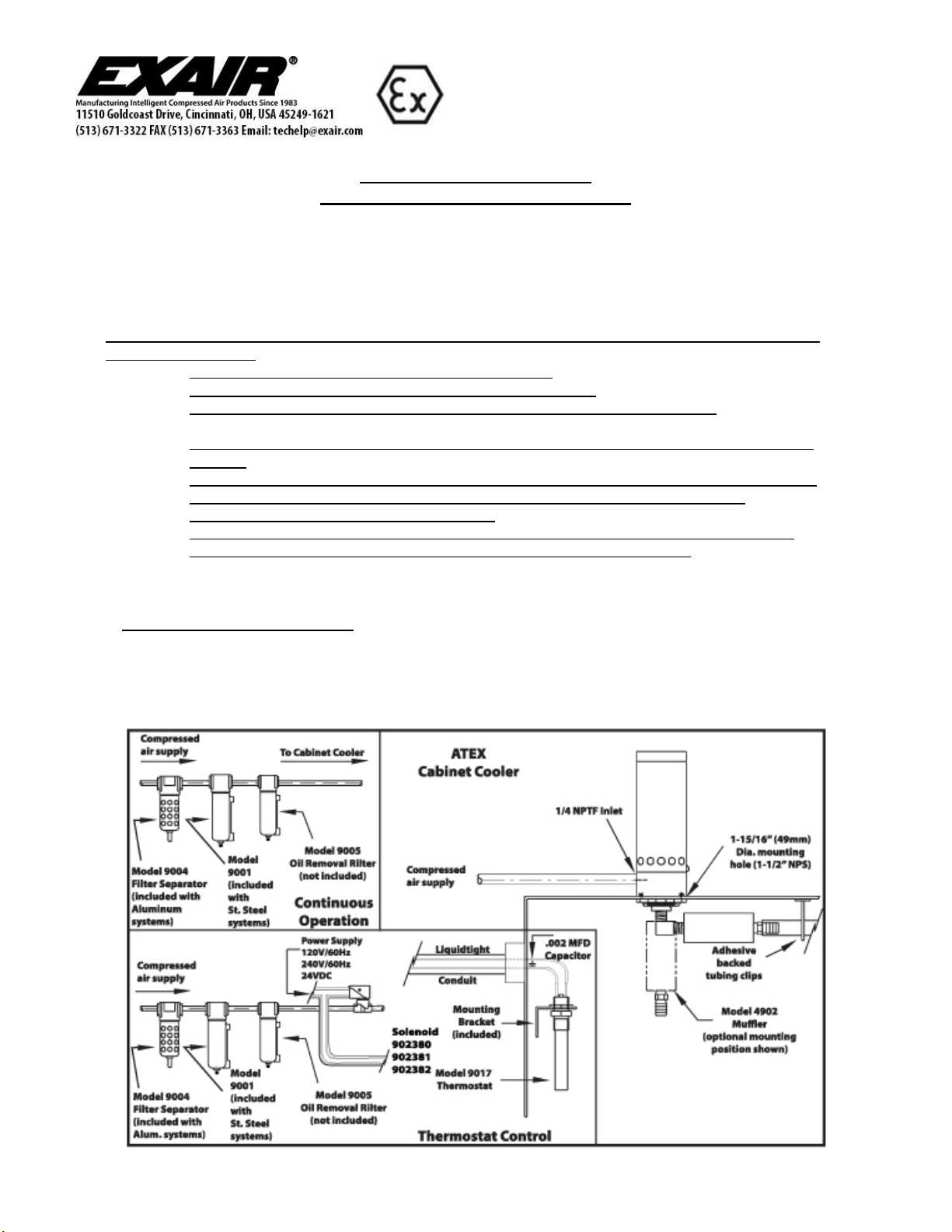
EXAIR’s ATEX Cabinet Cooler System cools electronic cabinets using compressed air through a vortex tube to remove
up to 2,800 BTU/HR of heat. The ATEX Cabinet Cooler is not itself a purged and pressurized control system, is not a part
of the controller and should not be relied upon nor used in place of a purged and pressurized controller. The ATEX
Cabinet Cooler System must be used in conjunction with a properly sized purged and pressurized enclosure that must be
able to vent the additional air introduced to the cabinet by the Cabinet Cooler. EXAIR does not supply purge or
pressurization systems. The vent supplied with purge system will need to be properly sized to vent the additional cool air
produced by the ATEX Cabinet Cooler System to prevent over-pressurization of the cabinet.
EXAIR ATEX Cabinet Coolers ATEX ZONE 2 AND 22 CERTIFIED.
COMPRESSED AIR LINE SIZES
Compressed air lines should be sized to hold pressure drops to a minimum. When installing supply lines, use 1/4" pipe for
runs up to 10' (3m). Use 3/8" pipe for runs up to 50' (15.2m), and 1/2" pipe for runs over 50' (15.2m). If using compressed
air hose, consider 3/8" I.D. hose to be the same as 1/4" pipe and 1/2" I.D. hose to be the same as 3/8" pipe. Do not use
restrictive fittings such as quick connects. They can “starve” the ATEX Cabinet Cooler by causing excessive line pressure
drop.
COMPRESSED AIR SUPPLY
With proper filtration and separation of dirt, moisture and oil from the compressed air supply, the ATEX Cabinet Cooler
will run for years with no maintenance required. Pressurized air supply provided to the Cabinet Cooler must be the same
quality (free of contaminants, instrument quality, compressor intake in unclassified location) as the air used in the purge
and pressurize the enclosure it is installed on. Filtering for contaminants and separation of moisture is required for all
ATEX Cabinet Coolers.
All ATEX Cabinet Cooler Systems include an Automatic Drain Filter Separator which provides 5-micron filtration. The
automatic drain is float actuated to eliminate the possibility of passing water into the enclosure, even during continuous
operation. (Impulse-type automatic drains must not be used. They may allow water to pass through the filter during
continuous operation.)
To prevent problems associated with oil, use an oil removal filter (Model 9005 Oil Removal Filter not included). The oil
removal filter should be used downstream from the automatic drain filter separator. Filters should be used close to each
ATEX Cabinet Cooler, within 10 to 15' (3 to 4.6m) is best.
Both the filter separator and oil removal filters should be located in a non-hazardous area, so that the filter can be changed
without introducing hazardous substances to the enclosure through the plumbing.
ATEX Cabinet Coolers are designed to use normal shop air supplies of 80 to 100 PSIG (5.5 to 6.9 BAR). Thermostat
control can minimize compressed air usage and should be used whenever possible.
USING THE ATEX CABINET COOLER
The ATEX Cabinet Cooler is suitable for ZONES 2 AND 22.
CE Ex II 3 G Ex h IIC T3 Gc
CE Ex II 3 D Ex h IIIC 200°C Dc
Install in accordance with applicable local code. Do not operate the cooler until the purge system on the enclosure
completed its initial cycle and a proper safe environment is created.
Note: The ATEX classification only applies to the Cabinet Cooler itself. The solenoid is separately ATEX certified. The
accessories (filter, cold air distribution kit and thermostat) are not ATEX certified.
The ATEX Cabinet Cooler mounts to the enclosure thru a 1-15/16" (49mm) 1-1/2" NPS diameter hole. A nut is supplied
to lock it in place. The ATEX Cabinet Cooler should be mounted on the top only (vertically). Side mounting is possible
with use of a Model 4907 90° Side Mount Kit. After mounting to the ATEX Cabinet Cooler, connect the Model 4902
muffler to the cold outlet of ATEX Cabinet Cooler. Disassembly is opposite of installation. Remove Model 4902 muffler
from the cold end. Unthread the nut on the bottom of the ATEX Cabinet Cooler and remove the ATEX Cabinet Cooler
from the cabinet.

LIT 4016
©2011 EXAIR Corporation
ATEX Cabinet Coolers will provide a 50°F temperature drop from supply air temperature at 100 PSIG (6.9 BAR). An
elevated inlet temperature will produce a corresponding rise in cold air temperature and reduction in cooling capacity.
Note: The poppet valve, provided with the Cabinet Cooler to prevent air from leaking out from the purged and
pressurized enclosure, must be verified during installation that it will not cause the purged and pressurized enclosure to
drop below the required minimum enclosure pressure when the cooler is not in service.
NOISE MUFFLING
All ATEX Cabinet Cooler Systems are equipped with sound muffling. The Model 4902 Cold Muffler (included) can be
easily installed on the cold air discharge (see diagram). With this muffler installed, the noise level is less than 75 dBA.
COLD AIR DISTRIBUTION KIT
The Model 4904 Cold Air Distribution Kit includes 8' (2.4m) of flexible (1/2" I.D.) vinyl tubing, (8) adhesive backed
clips to hold the tubing in place, (1) elbow and (1) end plug. The tubing is used to direct the cold air for circulation or to
hot spots, as needed. Holes may be drilled or cut (“V” shaped) in the tubing. If the end is plugged, use at least
(6) 1/8" (3.2mm) diameter holes in tube to eliminate excessive back pressure on the ATEX Cabinet Cooler.
HUMIDITY
The ATEX Cabinet Cooler incorporates a low-pressure relief valve for both the vortex tube and cabinet air exhaust. This
valve closes and seals when the cooler is not operating to maintain the integrity of the enclosure. During continuous
operation, relative humidity inside the enclosure stabilizes at 45%. No moisture condenses inside the enclosure.
THERMOSTAT
Warning: Any solenoid valve or thermostat used with the ATEX Cabinet Cooler must be used in a suitable
environment for these individual electrical requirements. For any questions about where to mount an electrical
device in a hazardous location please refer to local codes, the occupational safety and accident prevention
regulations, and the purge system manufacturer.
Some ATEX Cabinet Cooler Systems are supplied with thermostat control. Assuming a purge system is used, the Model
9017 Thermostat should be located inside the enclosure using the mounting bracket (included). The thermostat is not
position sensitive and should be mounted in a hot area inside the enclosure.
The electrical requirement is 120V/60Hz, 110V/50Hz, 240V, 50/60Hz or 24VDC, and should be connected to the hot
line supplying the solenoid valve. It is normally open, actuated closed, when the temperature rises. The thermostat is
preset at 95°F (35°C). It will normally hold that setting within + or - 2°F (1°C) inside the cabinet.
To change the temperature setting:
Use a cup, thermometer and meter to check continuity. Using the cup, mix hot and cold water until the thermometer
shows the desired temperature for the enclosure. Insert the plain end (not the threaded end) of the thermostat into the
water and check continuity across the leads. Adjust screw until switching occurs (slight turn of the adjusting screw). The
thermostat will be set to actuate at the temperature of the water.
If the temperature at the mounting location of the thermostat changes very slowly, the solenoid valve may chatter. This
can be corrected by changing the thermostat location or by adding the Model 4519 .002 Microfarad Capacitor across the
leads (included).
ATEX CABINET COOLER COLD FLOW
This information will be used to properly size a spark arrest vent for the purge system that needs to be used on any
ATEX Cabinet Cooler.
Cabinet Cooler Part Number
Maximum Cold Flow (SCFM)
ATEX4610, ATEX4610SS, ATEX4610SS-316
10.7
ATEX4615, ATEX4615SS, ATEX4615SS-316
16.1
ATEX4625, ATEX4625SS, ATEX4625SS-316
26.8
ATEX4630, ATEX4630SS, ATEX4630SS-316
32.2
ATEX4635, ATEX4635SS, ATEX4635SS-316
37.5
ATEX4640, ATEX4640SS, ATEX4640SS-316
42.9
LIT 4016
©2011 EXAIR Corporation
If you have any questions or problems, please contact:
EPUTEC Drucklufttechnik GmbH.
Haidenbucherstr. 1
86916 Kaufering
Phone: +49 8191 91 51 19 0
Fax: +49 8191 91 51 19 91
Website: www.eputec.de
SOLENOID VALVE
Systems with thermostat control include the Model 902380, 902381 or 902382 Solenoid Valve. Mount the solenoid valve
on the compressed air line between the filter and the ATEX Cabinet Cooler. The solenoid valve requires 120V/60Hz,
110V/50Hz, 240V/50/60Hz, or 24VDC supply. A green ground wire has been provided for grounding. All wiring should
be installed in liquid-tight conduit. The valve is normally closed, actuated open. In most cases, it is controlled by the
thermostat.
TROUBLESHOOTING & MAINTENANCE
If the ATEX Cabinet Cooler is not producing cold air, check the pressure by installing a gauge at the compressed
air inlet of the cooler. Large pressure drops are possible due to undersized lines, restrictive fittings and clogged filter
elements.
For replacement or repair filter and regulator parts, contact EPUTEC at +49 8191 91 51 19 0 or
This manual suits for next models
17
Table of contents


