Schmidt SS 20.651 User manual

SCHMIDT®Flow Sensor
SS 20.651
Instructions for Use

Instructions for Use SS 20.651 page 2
SCHMIDT®Flow Sensor
SS 20.651
Table of contents
1Important information.......................................................................3
2Application range.............................................................................3
3Mounting..........................................................................................4
4Electrical connection........................................................................7
5Commissioning..............................................................................15
6Service information........................................................................16
7Dimensions....................................................................................20
8Technical table ..............................................................................21
9Declaration of conformity...............................................................23
Imprint:
Copyright 2016 SCHMIDT Technology GmbH
All rights reserved
Version: 547608.02B
Subject to modifications

Instructions for Use SS 20.651 page 3
1 Important information
These instructions for use must be read completely and observed care-
fully, before putting the unit into operation.
Any claims under the manufacturer's liability for damage resulting
from non-observance or non-compliance with these instructions will
become void.
Tampering with the device in any way whatsoever - with the excep-
tion of the designated use and the operations described in these in-
structions for use - will forfeit any warranty and exclude any liability.
The device is designed exclusively for the use described below (see
chapter 2). In particular, it is not designed for direct or indirect protec-
tion of personal or machinery.
SCHMIDT Technology cannot give any warranty as to its suitability
for a certain purpose and cannot be held liable for errors contained in
these instructions for use or for accidental or sequential damage in
connection with the delivery, performance or use of this device.
The following symbol has to be observed:
Danger warnings and safety instructions. Read carefully!
Non-observance of these instructions may lead to injury of
personal or malfunction of the device.
2 Application range
The SCHMIDT®flow sensor SS 20.651 is designed for stationary
measurement of the flow velocity as well as the temperature of air. The
sensor measures standard velocity
1
wN(unit: m/s) based on standard
conditions of 1013.25 hPa and 20 °C. The output signal is linear and in-
dependent of pressure and temperature of the measured medium.
The basic version (without coating) is suitable only for clean air. Espe-
cially the occurrence with aggressive components (e.g. sulfur, fluor, na-
trium, chlorine, phosphor, etc.) can be done only on the customer's own
responsibility. With optional coating (Parylene) the sensor exhibits a
higher tolerance concerning pollution and an increased media re-
sistance. The respective suitability has to be considered in each case
due to the different environmental conditions.
When using the sensor outdoors, it must be protected against
direct exposure to the weather.
1
Corresponds to actual velocity under standard conditions
!
!

Instructions for Use SS 20.651 page 4
3 Mounting
Determination of the place of installation
Correct measurements require a flow low in turbulence. This can be
achieved by providing sufficiently long and straight distances without dis-
turbances in front of and behind the sensor.
The minimum inlet and outlet distances depend on the degree of dis-
turbance of the flow obstacle upstream of the measuring distance and
the inner pipe diameter
2
D (see Figure 1 and Table 1).
Figure 1
Flow obstacle
upstream of sen-
sor position
Minimum
length inlet
(L1)
Minimum
length outlet
(L2)
Light bend (< 90°)
10 x D
5 x D
Reduction,
expansion,
90° bend or
T-junction
15 x D
5 x D
Two 90° bends in
one plane (2-
dimensional)
20 x D
5 x D
Two 90° bends
(3-dimensional
change in direction)
35 x D
5 x D
Shut-off valve
45 x D
5 x D
Table 1 Minimum measuring distances depending on the flow obstacles
2
Minimum inner pipe diameter: 25 mm

Instructions for Use SS 20.651 page 5
Mounting method
The SS 20.651 is mounted by means of a through-bolt joint (included by
delivery) which clamps the sensor probe frictionally. Due to the different
operating conditions (temperature and pressure range), there are differ-
ent types (see Table 2):
Max. temperature
Max. pressure
fitting
seal
spare part no.
200 / 350 °C
atmospheric
brass
no
549311
200 °C
16 bar
1.4571
FKM
535092
350 °C
16 bar
1.4571
clamping ring
549312
Table 2 Types of compression fittings
Systems with overpressure
The SS 20.615 is designed for atmospheric conditions (standard), op-
tionally for a working pressure up to 16 bar. As long as the medium is
operated with overpressure, make sure that:
There is no overpressure in the system during mounting.
Mounting and dismounting of the sensor can be carried out
only as long as the system is in a depressurized state.
Only suitable pressure-tight mounting accessories are used.
Appropriate safety devices are installed to avoid unintended discard-
ing of the sensor due to overpressure.
For measurements in media with overpressure, appropriate
safety measures must be taken to prevent unintended dis-
carding of the sensor.
If other accessories than the delivered pressure protection kit or alterna-
tive mounting solutions are used, the customer must ensure the corre-
sponding safety measures.
Pressure-tight mounting, fastening of the screw pipe connec-
tion and discarding protection must be checked before pres-
sure is applied. These tightness checks must be repeated at
reasonable intervals.
All components of the pressure protection kit (bolt, chain and
bracket) have to be checked regularly for integrity.
!
!
!
!

Instructions for Use SS 20.651 page 6
Thermal boundary conditions
With medium temperatures exceeding the permitted ambient tempera-
ture of the electronic components, a free cooling section of the probe of
at least 50 mm must be provided (see Figure 2) to prevent the electronic
components located in the electronic housing from being influenced by
the temperature.
Figure 2
Make sure that the transmission of the medium temperature
does not cause the temperature to exceed the permitted oper-
ating temperature of the electronics.
On the housing side, the sensor tube should project out of the
measuring tube in the air (without insulation) at a length of at
least 50 mm (if ambient air is cold enough to cool it down).
Alignment of the sensor
The sensor head must be placed in the middle of the pipe (see Figure 1)
and adjusted correctly relative to the flow direction. A sensor mounted in
the wrong direction rotated by 180° leads to wrong (too high) measuring
values. As installation aid, a flow arrow is located on the enclosure cov-
er. It must corresponds to the flow direction.
The tilting of the measurement direction relative to the flow must not ex-
ceed ± 3°, otherwise it can lead to major measurement deviations
3
.
The sensor measures unidirectionally and must be adjusted
correctly relative to the flow direction.
The axial tilting of the sensor head relative to the flow direc-
tion should not exceed 3°.
General note:
Do not use the aligning surface of the housing for mechanical
alignment, such as locking. There is a risk of damage to the
sensor.
3
Deviations > 1% of the measured value
!
!
!

Instructions for Use SS 20.651 page 7
4 Electrical connection
Make sure that no operating voltage is active during electrical
installation and that the operating voltage cannot be switched
on inadvertently.
Specification of the plug-in connector (firmly integrated in the housing):
Number of connection pins: 8 (plus shield connection at the metallic housing)
Type: male
Fixation of connecting cable: M12 thread (spigot nut at the cable)
Type of protection: IP67 (with screwed cable)
Model: Binder, series 763
Pin numbering: View of plug-in connector of the sensor
Figure 3
Pin assignment of the connector can be seen in the following Table 3.
Pin
Designation
Function
Wire color
1
Pulse 1
Output signal flow / volume (digital: impulse)
White
2
UB
Operating voltage: 24 VDC ± 20%
Brown
3
Analog TM
Output signal temperature of medium (analog: U / I)
Green
4
Analog wN
Output signal flow (analog: U / I)
Yellow
5
AGND
Reference potential for analog outputs
Gray
6
Pulse 2
Output signal flow / volume (digital: relay)
Pink
7
GND
Operating voltage: Ground
Blue
8
Pulse 2
Output signal flow / volume (digital: relay)
Red
Shield
Electromechanical shielding
Meshwork
Table 3
The analog signals have an own AGND reference potential which is di-
rectly connected to GND of the operating voltage within the sensor.
The specified wire colors are valid using a connecting cable delivered by
SCHMIDT®.
The appropriate protection class III (SELV) respective PELV
(EN 50178) has to be considered.
!
!

Instructions for Use SS 20.651 page 8
Operating voltage
For proper operation, the sensor requires DC voltage with a nominal val-
ue of 24 VDC with a permitted tolerance of ± 20 %.
Deviating values can lead to measurement errors or even defects and,
therefore, should be avoided.
Only operate the sensor in the defined range of operating volt-
age (24 VDC ± 20 %).
Undervoltage may result in malfunction, overvoltage may lead
to irreversible damage.
The operating current of the sensor (including analog signal currents) is
normally approx. 50 mA (max. 250 mA).
The specifications for the operating voltage are valid for the connection
to the sensor. Voltage drops generated due to line resistances must be
taken into account by the customer.
Wiring of analog outputs
Both analog outputs, for flow and temperature, are designed as high-side
drivers with "Auto-U/I" characteristic which are short circuit protected
against both rails of the operating voltage.
The loading resistance RLmust be connected between the correspond-
ing signal output and the electronic reference potential AGND or GND of
the sensor.
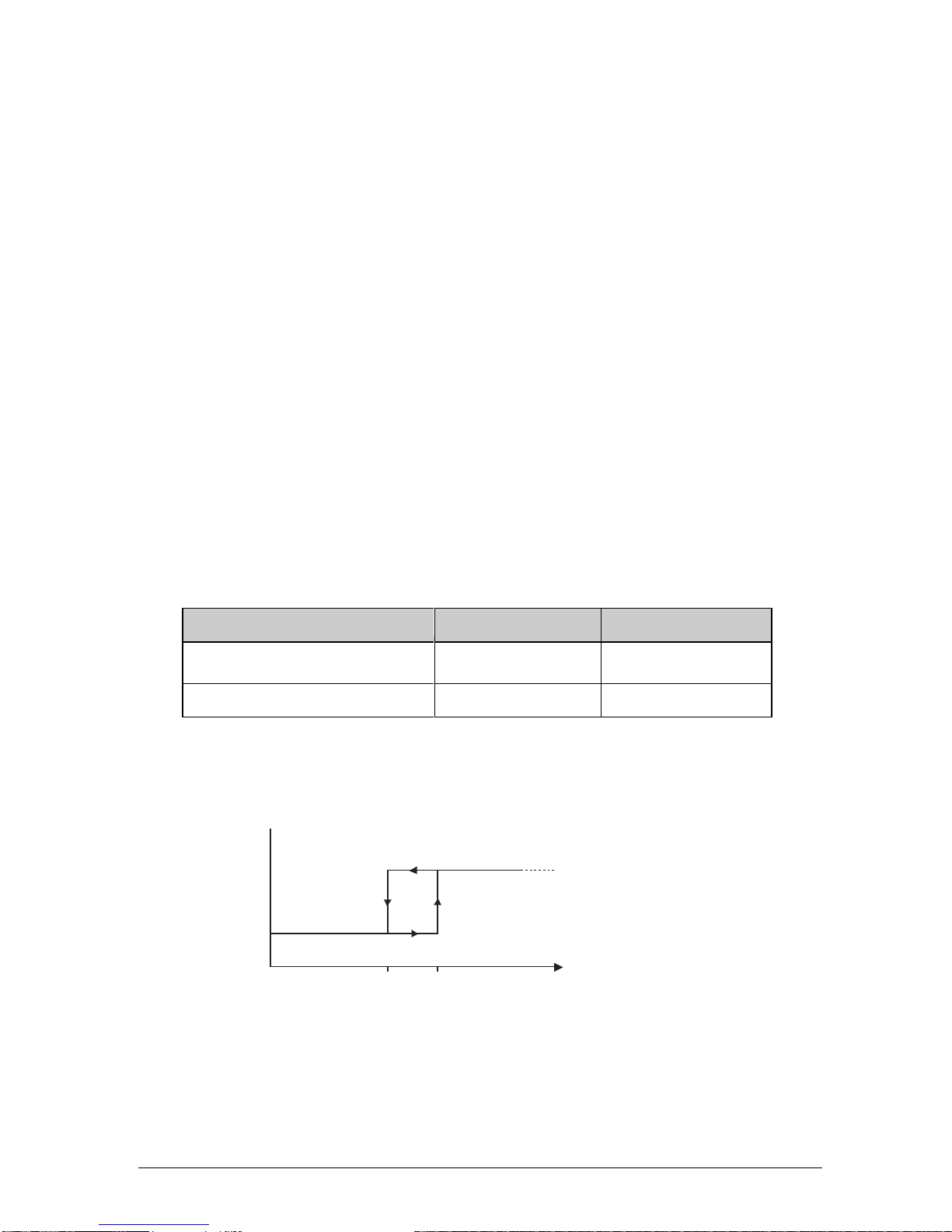
Depending on the resistance value RL, the signal electronics switches
automatically between its operation as voltage interface (mode: U) or
current interface (mode: I), hence the designation "Auto-U/I". The switch-
ing threshold is in range between 500 and 550 (for details, refer to the
next subchapter Signaling of analog outputs).
However, a low load resistance value in voltage mode may cause signifi-
cant voltage losses via line resistances RW,S, which can lead to measur-
ing errors.
For the voltage mode, a measuring resistance of at least
10 kis recommended.
The maximum load capacity CLis 10 nF.
!
!

Instructions for Use SS 20.651 page 9
The following points must be also taken into account:
Use of only one analog output
It is recommended to terminate both analog outputs with the same
resistance value, even if only one of the two analog outputs is used.
Unused analog outputs
In this case, both outputs can remain disconnected or should be
terminated with high impedance against A/GND (with the same re-
sistance value).
Short circuit mode
In case of a short circuit against the positive rail of the operating
voltage (+UB), the signal output is switched off.
In case of a short circuit against the negative rail (A/GND) of the op-
erating voltage, the output switches to current mode (RLis calculated
to 0 ) and provides the required signal current.
If the signal output is connected to +UBvia a resistance, the value RL
is calculated incorrectly and false signal values are caused.
Signaling of analog outputs
Switching characteristic “Auto-U/I”
Range of resistance value RL
Signaling mode
Signaling range
≤ 500 (550)
Current (I)
4 ... 20 mA
> 500 (550)
Voltage (U)
0 ... 10 V
Table 4 Switching characteristic “Auto-U/I”
A hysteresis of approx. 50 ensures a stable transition behavior
which is shown in Figure 4 below.
Figure 4
Depending on the set output signal, accuracy of the switching point
detection can be reduced. Therefore, it is recommended to select the
R [ ]
L
0500 550
Modus
I
U
Mode

Instructions for Use SS 20.651 page 10
load resistance RLin such a way that a secure detection can be
maintained (< 300 for current mode and > 1 kfor voltage mode).
For measuring of RLin an actual zero signal (voltage mode), the
electronics generates test pulses that correspond to an effective val-
ue of approx. 1 mV. However, the latest measuring devices may trig-
ger in response to such a pulse in the DC voltage measuring mode
and display short-term measuring values of up to 20 mV. In this
case, it is recommended to install an RC filter before the measuring
input with a time constant of 20 … 100 ms.
Severe interferences on the connection cable may shift the switching
threshold outside specification. In this case the use of isolated ampli-
fiers for the measuring signals is recommended.
Error signaling
In current mode, the interface outputs 2 mA
4
.
In voltage mode, the output switches to 0 V.
Representation of measuring range
The measuring range of the corresponding measuring value is
mapped in a linear way to the signaling range of its associated ana-
log output, depending on signal type.
For flow velocity measurement, it ranges from zero flow to the end of
the measuring range wN,max (see Table 5).
Voltage mode (U)
Current mode (I)
wNOut
N
NU
V
w
w,
max,
10
)4(
16 ,
max, mAI
mA
w
wwNOut
N
N
Table 5 Representation specification for flow measurement
The measuring range of the medium temperature TMstarts at 0 °C
and reaches up to TM,max = 200 / 350 °C (see Table 6).
4
In accordance with the Namur specification
110 wN [%]
020 40 8060 100
IOut
[mA]
20
4
21,6
12
8
16
U
Out
[V]
0
110
w
N
[%]
10
0
20
11
40
80
60
100
4
2
6
8

Instructions for Use SS 20.651 page 11
Voltage mode (U)
Current mode (I)
TMOut
M
MU
V
T
T,
max,
10
)4(
16 ,
max, mAI
mA
T
TTMOut
M
M
Table 6 Representation specification for measurement of medium temperature
Exceeding measuring range of flow velocity
Measuring values bigger than wN,max are output in a linear way up to
110 % of the signaling range (this corresponds to maximum 11 V or
21.6 mA, see images in Table 5). In case of even higher values of
wN, the output signal remains constant.
Error signaling does not take place.
Medium temperature outside specification range
An operation beyond the specified limits can lead to damage to the
sensor and, therefore, is considered as a critical error. Depending on
the temperature limit
5
, this leads to the following reaction (see also
images in Table 6):
oMedium temperature below 0 °C:
The analog output for TMswitches to error (0 V or 2 mA).
The measuring function for flow velocity is switched off; its ana-
log output also signals an error (0 V resp. 2 mA).
oMedium temperature above 200 / 350 °C:
TMis output in a linear way up to 200 / 350 °C + 10 %.
Above this critical limit flow measurement is switched off and its
analog output switches to error (0 V or 2 mA). The signal output
for TMswitches, contrary to standard error signaling, directly to
the maximum values of 11 V resp. 22 mA.
5
The switching hysteresis for decision threshold is approx. 5 K.

Instructions for Use SS 20.651 page 12
Wiring of pulse output (high-side driver)
The pulse output is current-limited, short-circuit protected and exhibits
the following technical characteristics:
Design: High-side driver, open collector
Minimum high level US,H,min: UB–3 V (with maximum switching current)
Maximum low level US,L,max: 0 V (load resistance RLto GND required)
Short circuit current limit: approx. 100 mA
Maximum leakage current IOff,max: 10 µA
Minimum load resistance RL,min: depending on supply voltage UB(see below)
Maximum load capacitance CL: 10 nF
Maximum cable length: 100 m
Wiring:
Figure 5
The pulse output can be used as follows:
Direct driving of low-impedance loads (e.g. optocoupler, relays, etc.)
with a maximum current consumption of approx. 100 mA.
This allows calculating the minimum permitted (static) load re-
sistance RL,min depending on the operating voltage UB
6
:
AVU
RB
L1.0 3
min,
Example:
In case of the maximum permissible operating voltage of
UB,max = 28.8 V the minimal load is RL,min = 258 Ω.
Here the excessive heating power of the load has to be considered.
The pulse output is protected by means of different mechanisms:
Current limiting:
The analog current is limited to approx. 100 mA.
If the load values are too low, the output switches to chopping (cycle
of 300 ms with interconnection phases of approx. 100 µs).
The maximum load capacitance CLis 10 nF. A higher capacitance
reduces the limit of the current limiter.
6
Overcurrent peaks are absorbed by the short circuit limiter.

Instructions for Use SS 20.651 page 13
In case of a high capacitive load CL, the inrush current im-
pulse may trigger the quick-reacting short-circuit protection
(permanently) although the static current requirement is be-
low the maximum current IS,max. An additional resistor con-
nected in series to CLcan eliminate the problem.
Protection against overvoltage.
The pulse output is protected against short-term overvoltage peaks
(e.g. due to ESD or burst) of both polarities by means of a TVS di-
ode
7
. Long-term overvoltage destroys the electronics.
Overvoltage can destroy the pulse output.
Wiring relay
The output is realized by a semiconductor relay with following technical
characteristics:
Type: SSR (PhotoMOS relay)
Maximum leakage current IOff,max: 2 µA
Maximum resistance RON: 16 Ω(typ. 8 )
Maximum switching current IS: 50 mA
Maximum switching voltage US: 30 VDC / 21 VAC,eff
Wiring:
Figure 6
The relay output is protected against short-term overvoltage peaks (e.g.
due to ESD or burst) of both polarities by means of a TVS diode. Long-
term overvoltage destroys the electronics.
Exceeding the specified electrical operating values lead to irre-
versible damage.
Protective measures for incorrect wiring or overload are not
taken for this output.
7
Transient Voltage Suppressor Diode, breakdown voltage approx. 30 V, peak pulse capac-
ity 4 kW (8 / 20 µs)

Instructions for Use SS 20.651 page 14
Signaling of pulse outputs
Both pulse outputs represent the same information synchronously
whereas two measurands are selectable:
The actual flow velocity wN= 0 … wN,max is mapped proportionally to
the frequency range f = 0 …fmax (see Figure 7):
- Standard version: fmax = 100 Hz
- Optional selectable maximum frequency (fmax = 10 … 99 Hz)
Figure 7 Example for fmax = 100 Hz
Hzf100...10
max
max,
max N
w
f
f
N
w
max,
max N
V
f
f
N
V
N
V
: Standard volume flow
The volume flow and the pulse valence VN,Imp (= volume per pulse)
can be determined on base of output frequency, measuring range of
the sensor and inner pipe diameter D:
2
4DPF
N
w
D
APF
N
w
N
V
;
max
max,
Imp, f
N
V
N
V
Another option supplies pulses with a fixed pulse valance of
1 m³/pulse.
To do this, the pipe diameter must be specified when ordering
(minimum inner pipe diameter: Dmin = 20 mm).
Exceeding measuring range of the flow wNis also output up to 110 % of
the measuring range. The output of higher flow values is limited to 110 %
of the measuring range.
If an error occurs, 0 Hz or no pulses will be output. The current initial
state remains unchanged.
Note:
The relay can be used as a S0-Interface according DIN 43 864.
f
Out
[Hz]
0110 w
N
[%]
100
020
110
40 8060 100
40
20
60
80

Instructions for Use SS 20.651 page 15
5 Commissioning
The valid measuring ranges are specified on the rating plate.
After applying the supply voltage, the sensor signals the initialization of
the measuring operation by means of all four LEDs (sequence: red, or-
ange and green).
If the sensor detects a problem during initialization, it signals the problem
according to Table 7. An extensive overview of errors and their causes
as well as troubleshooting measures are listed in Table 8.
If the sensor is in the correct operational state, it switches to the measur-
ing mode after initialization. Flow velocity indication (both LEDs and sig-
nal outputs) switches for a short period to maximum and levels off at the
correct measuring value after about 10 seconds, if the sensor probe al-
ready has the medium temperature. Otherwise, the process will last
longer until the sensor has reached the medium temperature.
LED display
No.
State
LED 1
LED 2
LED 3
LED 4
1
Ready for operation & flow < 5%
2
Flow > 5%
3
Flow > 20%
4
Flow > 50%
5
Flow > 80%
6
Flow > 100% = overflow
7
Sensor element defective
8
Operating voltage too low
9
Operating voltage too high
10
Electronics temperature too high
11
Electronics temperature too low
12
Medium temperature too low
13
Medium temperature too high
List of abbreviations
LED off
LED on: orange
LED on: green
LED flashes (approx. 2Hz): red
Table 7 LED signals of sensory functions

Instructions for Use SS 20.651 page 16
6 Service information
Maintenance
Contaminations of the sensor head lead to distortion of the measured
value and can damage the sensor chip.
Therefore, the sensor head must be checked for contamination at least
every six months. If contaminations are visible, the sensor must be
cleaned as described below and examined with respect to flow at a cer-
tain volume flow (calibration). Ideally, the entire characteristic line of the
sensors should be calibrated by SCHMIDT Technology.
If the maintenance is performed not properly or not at the re-
quired intervals, the warranty will be rendered.
Cleaning of the sensor head
If the sensor head is dusty or contaminated, it can be carefully cleaned
by means of compressed air.
The sensor head is a sensitive measuring system.
During manual cleaning proceed with great care.
In case of persistent deposits, the sensor chip and the inside of the
chamber head can be carefully cleaned with the help of alcohol that dries
out without leaving residues (e.g. isopropyl alcohol) or soap water with
special cotton buds.
Cotton buds of the mark "CONSTIX Swabs" type "SP4" manufactured by
"CONTEC" with small, gentle cotton pads are approved for this purpose
(see Figure 8). The narrow side of these pads fits exactly between
chamber head wall and sensor chip and exerts thus a controlled, mini-
mum pressure on the chip. Conventional cotton pads are too large and
can break the chip.
Do not try to apply great force to the chip (e.g. using cotton
pads with too thick head or making levering movements with
the pad).
Mechanical overload of the sensor element may lead to irre-
versible damage.
Move the cotton pad with great care back and forth parallel to the sur-
face of the chip to rub off the contamination. Use several cotton pads if
required.
!
!
!

Instructions for Use SS 20.651 page 17
Figure 8 Approved cotton pads with narrow cleaning pads
For washing off the sensor element, a short rinsing with liquid (preferably
using cleaning agents or alcohol that dry out without leaving residues) is
allowed. Immersion of the sensor head into liquids is not permitted.
Immersion into liquids is not permitted and can irreversibly
damage the sensor head.
Before putting the sensor head into operation again, wait until it is com-
pletely dry. The drying process can be accelerated by careful blowing off.
If this procedure does not help, the sensor must be sent to SCHMIDT
Technology for cleaning or repair.
Eliminating malfunctions
The following Table 8 lists possible errors (error images). A description
of the way to detect errors is given. Furthermore, possible causes and
measures to be taken to eliminate errors are listed.
Causes of any error signaling have to be eliminated imme-
diately. Significant exceeding or falling below the permitted
operating parameters can result in permanent damage to the
sensor.
!
!

Instructions for Use SS 20.651 page 18
Error image
Possible causes
Troubleshooting
Problems with the supply
voltage UB:
No UBpresent
UBhas wrong polarity
UB< 15 V
Sensor defective
Is the plug-in connector
screwed on correctly?
Is supply voltage connect-
ed to sensor (cable break,
field connect)?
Is the power supply unit
large enough?
No LED is lit
All signal outputs at zero
Start sequence is repeated
continuously (all LEDs red
- yellow - green)
UBunstable:
Power supply unit unable
to supply the switch-on
current
Other consumers overload
UB
Cable resistance too high
Is the supply voltage at
the sensor stable?
Is the power supply unit
large enough?
Are the voltage losses
over cable negligible?
Sensor element defective
Return the sensor for repair
Supply voltage too low
Increase supply voltage
Supply voltage too high
Reduce supply voltage
Electronic temperature too
low
Increase operating tempera-
ture of the environment
Electronic temperature too
high
Lower operating temperature
of the environment
Medium temperature too low
Increase medium tempera-
ture
Medium temperature too
high
Lower medium temperature
Low signal wNis too large /
small
Measuring range too small /
large
I-mode instead of U-mode or
vice versa
Sensor element soiled
Check sensor configuration
Check type or measuring
resistance
Clean sensor head
Flow signal wNis fluctuating
UBunstable
Mounting conditions:
Sensor head is not in the
optimum position
Inlet or outlet is too short
Strong fluctuations of pres-
sure or temperature
Check the voltage supply
Check mounting conditions
Check operating parameters
Analog signal voltage per-
manently at maximum
Load resistance of signal
output connected to +UB
Connect load resistance to
AGND
Analog signal voltage per-
manently at zero
Error signaling
Short circuit against (A)GND
Eliminate errors
Eliminate short circuit
Table 8

Instructions for Use SS 20.651 page 19
Transport / Shipment of the sensor
Before transport or shipment of the sensor, the delivered protective cap
must be placed onto the sensor head. Avoid contaminations or mechani-
cal stress.
Calibration
If the customer has made no other provisions, we recommend repeating
the calibration at a 12-month interval. To do so, the sensor must be sent
in to the manufacturer.
Spare parts or repair
No spare parts are available, since a repair is only possible at the manu-
facturer's facilities. In case of defects, the sensors must be sent in to the
supplier for repair.
A completed declaration of decontamination must be attached.
The “Declaration of decontamination” form is attached to the sensor and
can also be downloaded from
www.schmidttechnology.com
under “Downloads” in “Service returns”.
If the sensor is used in systems important for operation, we recommend
you to keep a replacement sensor in stock.
Test certificates and material certificates
Every new sensor is accompanied by a certificate of compliance accord-
ing to EN 10204-2.1. Material certificates are not available.
Upon request, we shall prepare, at a charge, a factory calibration certifi-
cate, traceable to national standards.

Instructions for Use SS 20.651 page 20
7 Dimensions
Compact sensor
Figure 9
Remote sensor (including wall mounting bracket)
Figure 10
Other manuals for SS 20.651
1
Table of contents
Other Schmidt Accessories manuals

Schmidt
Schmidt SS 20.261 User manual

Schmidt
Schmidt SS 20.500 User manual

Schmidt
Schmidt SS 20.700 User manual

Schmidt
Schmidt SS 20.500 Ex User manual

Schmidt
Schmidt SS 23.400 ATEX 3 User manual

Schmidt
Schmidt SS 20.60 User manual

Schmidt
Schmidt SS 20.600 Ex Wiring diagram

Schmidt
Schmidt SS 20.600 User manual

Schmidt
Schmidt SS 20.501 User manual

Schmidt
Schmidt SS 20.600 User manual