NVB -150 User Manual
NVB -150 User Manual
www.ens-sys.co.kr
www.ens-sys.co.kr
Main Menu Initial Screen Menu Detailed Menu Function
Data
File Management
File Management Selecting Data Type
Open File Open File
Delete File Deleting File
Open Vibration File Measuring Information Vehicle Information and Channel
Open Result Value Playback
Open Noise File Measuring Information Vehicle Information and Channel
Open Result Value Playback
Open Balance File Measuring Information Vehicle Information and Channel
Open Result Value Result Value and Weight Distribution
Configuration
Setup
Measuring Time 5Sec, 10Sec, 20Sec, 30Sec, Trigger
Desired RPM Setting 3500 RPM
Setting Frequency Vibration and Noise Frequency
Sensor Setting Channel, Gain Setting Gain Value
Cal. Channel Calibration Selecting Channel, Vibration, Noise
Calibration Progress Calibration Level, Sensor Sensitivity
System
Volume Volume Adjusting Volume
LCD(Contrast Adjustment) LCD(Contrast Adjustment) Adjusting Contrast
Date Date MM/DD/YY/HH/MM/SS
System Information(Advanced) System
Information(Advanced) System Version, Updating
Software Menu
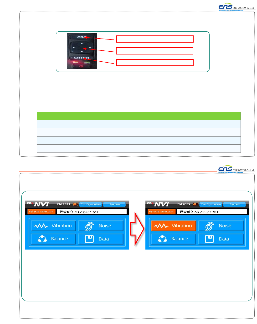
6-2-1. Display Area
UI Display
1. NVB-150 Software consists of 4 areas :<Navigation Area>, <Tab Button Area>, <Contents Area> and
<Start Button Area>.
2. <Navigation Area> shows where you are now.
3. <Tab Button Area> helps you to proceed to the next step.
4. <Contents Area> shows status of your information and progress of your results,
<Contents Area> also includes selection and start button.
5. <Start Button> helps you to approve or cancel your process and proceed to the next step.
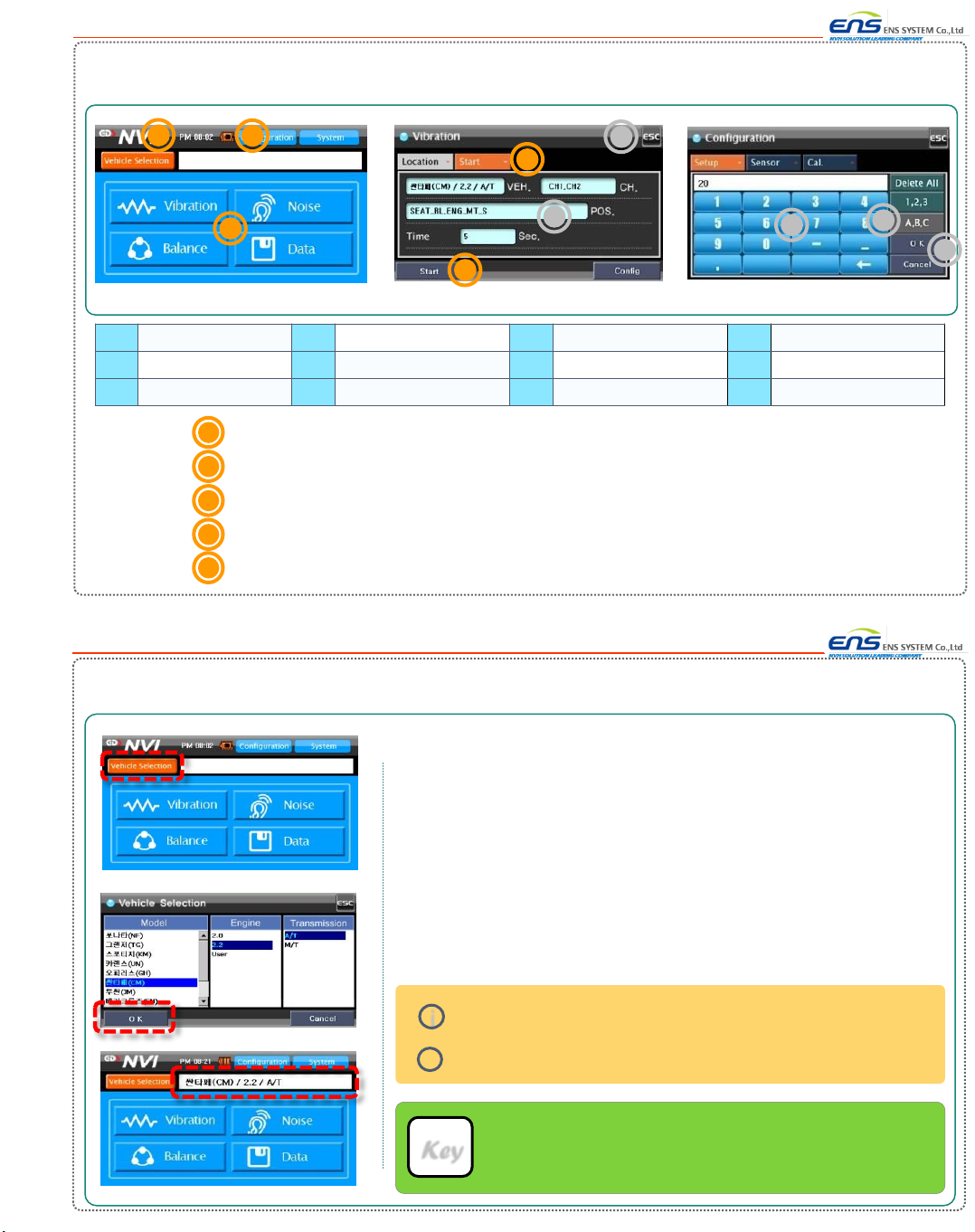
Navigation Area
1
Tab Button Area
2
Start Button Area
4
3Contents Area
1
3
4
2
1. Display consists of either 4 areas or 3 areas.
2. Above displays are an example.
17
18
6-2. Display