Exapta UniForce Guide
INSTALLATION & ADJUSTMENT
of
Exapta
7
s UniForce
J
hydraulic downforce system
for JD 1890 CCS, 1990 CCS (dual-rank CCS) air drills
including Pro-series openers
(See different instructions for air drills with air carts, single-rank CCS, box drills.)
Installing the cylinders:
1) Remove big coil spring on each opener: Lower the openers until they’re touching the ground or
shop floor, then put circuit in Float. Note: Only remove the first nut from OEM spring’s rod (the
second nut pre-loads the spring; no need to mess with it). Knock out roll-pin (roll-pin punch
provided). Coil spring & rod/clevis apparatus lift out.
2) The lower end of cylinder’s rod slides into cast bushing;
seat it with several whacks from a rubber mallet on a solid
surface (adding a drop of red Loctite is wise; provided)
(Note: turning the bushing on the rod by hand often allows it
to go easily; if bushing won’t go into position, use fine
emery cloth in bushing hole).
3) Install fittings into each cylinder’s port (use 90-degree
fittings where noted on the schematic). Tighten all fittings
(90s should be pointed primarily forward/up).
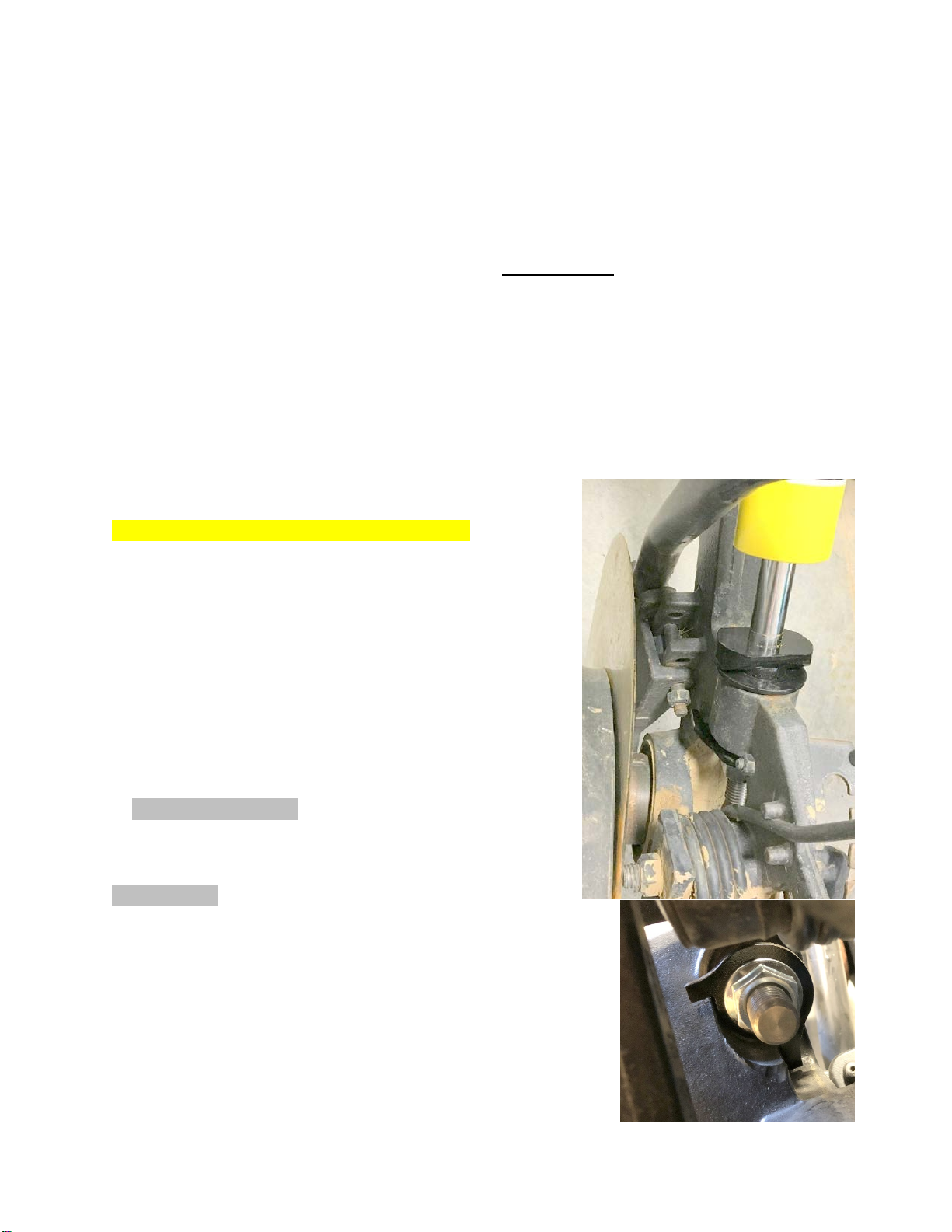
4) Set cylinder + bushing into large flat washer, then into
hole in cast opener (see photo A).
5) For 90-series openers: From bottom side of opener
casting, the notched plate slides over cylinder rod and its
ears go forward over the opener arm (see photo A). Position
the ear of plate behind/below nut on boot attachment bolt.
On Pro-series, see Photo B for orientation of notched plate.
Secure notched plate with 3/4" flange locknut, being sure prongs
on the end of bushing mate into notches of plate as you tighten.
Tighten nut sufficiently that notched plate draws tight against
lower end of bushing (Note: bushing is longer than hole in the
shank).
6) Insert pin into top clevis of cylinder, and secure with roll-pin.
_______________________
U.S. Patent 9,930,822; other Patents Pending. Instr. revised 4 July 2019.
Photo A
Photo B
(Pro-series)
Installing supports for header hoses:
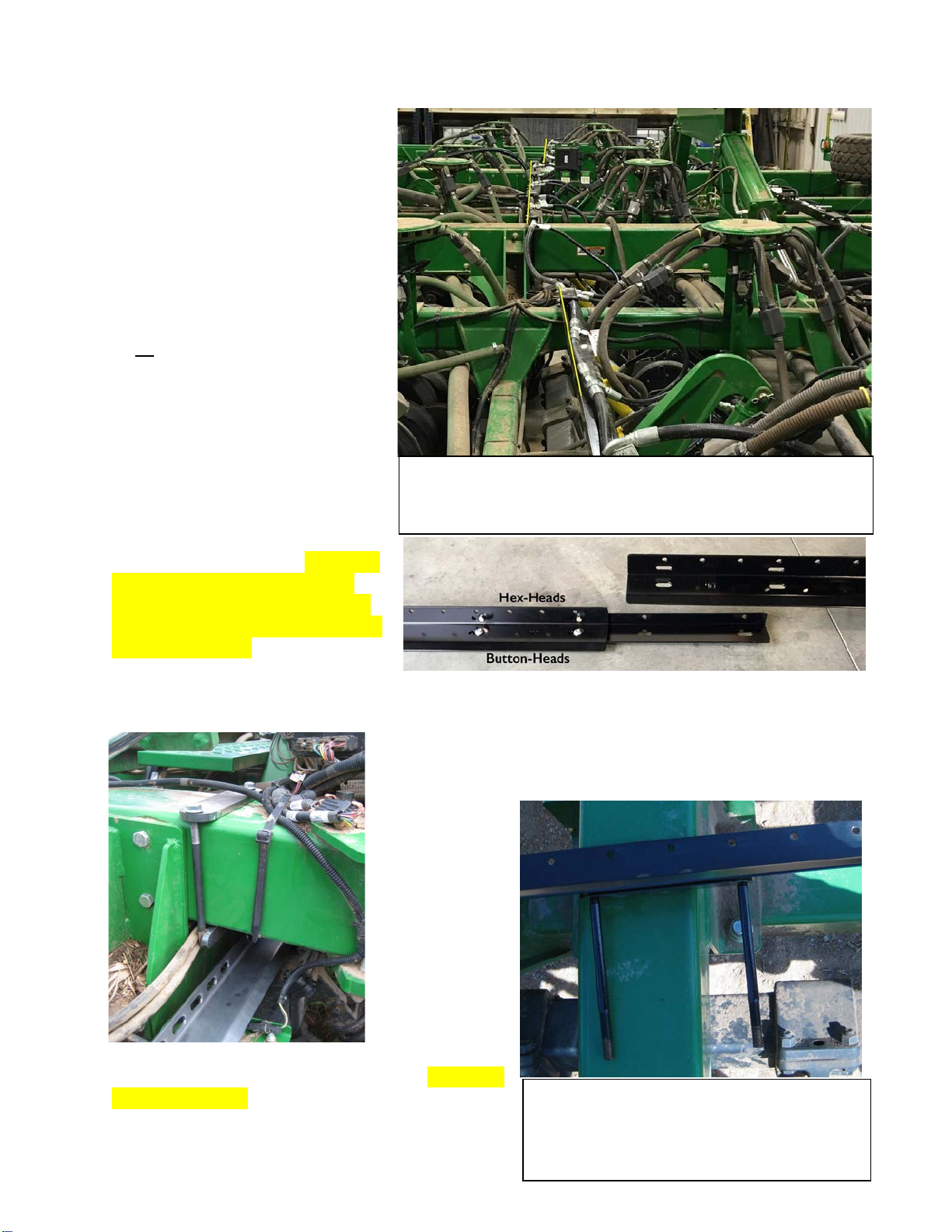
1) Trays are positioned directly
above the rank of openers that they
serve. Position center trays at an
offset fore/aft so they aren’t directly
in line with wing trays (see Photo
B) (they need clearance when wings
fold). Center front trays are spliced
on 40 & 42/43-ft models; center
rear (low-profile) trays are spliced
on all CCS drills. Locate the halves,
and prepare* to fasten them
together using splicer (sheet metal
piece that fits on underside of tray
to join the halves), and ½" x 3/4"
button-head bolts and flange
locknuts on bottom (button-heads
on inside, where hose will lie), and
with 5/16 x 3/4" hex-head bolts, flat
washer & locknuts on the side
(upright portion of tray). Be sure to
fasten the tray ends together that
have only 4 holes, not the series of
holes which belong on outer ends of
tray (see Photo C). (*Some tray
splices are most easily joined after
sliding each half into position, rather than pre-assembling—especially center-rear.)
2) For the front center trays, locate brackets #0002 and place
them on the drill’s center-section frame, over the fore/aft tubes
(see Photo E—it’s the same concept for all these brackets,
except the rear
center where the
bracket comes
up from
underneath).
Slide the 8" bar
onto the
brackets’ studs
from
underneath, and
then ½" flange
locknuts—but
don’t tighten yet. Fasten front center tray to front
brackets with ½" x 3/4" button-head bolts using blue
Loctite (provided). (Loctite isn’t needed on anything
secured with a flange locknut.) Center rear rank
uses brkt #0007 which goes onto fore/aft frame tube
Photo D.
Center section,
rear.
Brkt #0007.
Photo E. RH wing: front, outer end. Brkt #0004.
Tray is attached via ½ x 3/4" buttonhead bolts
threaded into U-bracket. Assembly pulled up
off the frame tube for viewing.
Photo B. Yellow lines show the offset of tray position on center vs
wings. This is an 1895, hence the extra towers and extra rank. All
trays go on top of frame tubes except center rear on CCSs.
Photo C

from underneath, and bar on top. See photo D.) Assemble low-profile center-rear trays and attach
to brkt using buttonhead bolts. Tighten all bolts & locknuts.
3) Trays for wings are single-piece. Front wing trays attach their inner end using brkts #0005. For
outboard end, use #0004. Install front trays as far forward as possible (but square to drill frame,
not angled). Install all wing trays as far to the outboard direction as possible. Tighten all bolts &
locknuts.
4) Rear wing trays on inner end use a slotted bracket #0006 (Photo F)
(#0013 for an 1895) that sets over rear gusset of frame tube, with 1/2" x
5.5" thru-bolt holding it. Outer end of tray uses brkt #0003 (Photo G).
5) If rear rank is being
equipped with
UniForce, swap out
OEM bracket that holds
electrical box for
Exapta’s (see Photo H).
This must be done for
clearance when folding.
6) Carefully fold drill’s
wings, making sure
trays don’t hit each
other. Now, tighten flange locknuts holding tray
brackets in place.
Photo H. When rear rank
gets UniForce, the electrical
bracket must be replaced w/
Exapta’s #0023 (shown).
Photo F. LH wing:
rear tray, inner end.
Brkt #0006. Thru-bolt
not yet installed here.
Photo G. RH wing: rear tray, outer end. Brkt
#0003. Button-head bolts need to be tightened
yet. Header hose is already assembled & lying
across the U-bracket here.

Installing header hoses:
1) For each rank of each drill section, organize header hoses & fittings per schematics provided.
These are ¾" hoses of different lengths (which are the numbers—in inches—on the hose in
schematic). Put all pieces together, but don’t tighten them yet (these are flared [JIC] fittings that
don’t need Teflon tape; also note that flared fittings should thread on easily for a long way before
you need a wrench—if not, you are cross-threaded). On T-fittings for drop hoses that are ¾",
install the reducer fitting to ½" JIC.
2) Tighten all fittings on header hose such that all T-fittings for drop hoses are aimed horizontal &
rearward (fittings for feeder hoses from the manifold should be pointed straight up; and fittings
for cross-flow hoses on each wing should be pointed straight up).
3) Install the drop hoses
(½" hoses from header to
cylinder), using specific
lengths as noted in the
schematic: S = 21", M =
31", L = 38", XL = 44".
Tighten all fittings.
4) Install ¾" x 46"
‘bridge’ hoses at hinge
points for wings—these
span the gap between
header hoses (see Photo
M). Tighten all fittings.
Tether hoses so they stay
away from pinch points.
5) Install the ¾ x 56" cross-flow hoses between front & rear ranks on each wing section. These
have large elbows built-in on both ends. Tighten all fittings.
Photo M. ‘Bridge’ hose between drill sections in upper-left of pic.

Installing valve block, etc:
1) Locate bracket to secure UniForce manifold (valve block) onto frame, and attach it to underside
of valve block with 4 screws w/ countersunk heads (use blue Loctite, provided). Set the bracket’s
legs (bolts) over frame at front-center of drill. Locate the bars that clamp bracket into position,
slide them over bracket’s stud bolts, and then flange locknuts—do not tighten yet.
2) There will be at least 2 cartridges installed (in the 2 – 3 front ports below/near gauge), and 2 – 3
corresponding rear ports used for short feeder hoses. Fittings are used to connect the 2 – 3 short
feeder hoses
(3/4") to
each other
approx 20"
downstream
(rearward)
of valve
block (if an
accumulator
is used, it
plumbs into
this location
as well),
then into 2
long feeder
hoses. See
Photo N.
3) Using
UniForce
manifold’s
1" ports on RH side (RH when facing the direction of travel) (these are engraved ‘P1’ & ‘T1’)
screw in the 90º elbows, and then to the 165" x ¾" hoses that go to the tractor, then into the high-
flow (5/8" body) male quick-coupler tips (provided) + adaptors (provided). Tighten all fittings.
Zip-tie the long hoses as they run along drill’s tongue (large zip-ties provided).
4A) If the tractor has a spare remote, the preferred setup is to run UniForce separately on that
remote. The LH ports (3/4") (‘P2’ & ‘T2’) of the UniForce manifold should have plugs in them.
4B) If no extra remote is available, UniForce can run on the same circuit as the OEM rockshaft
unless the drill has been updated to a Power-Beyond valve block. (There are some minor
complications when running both systems on the same circuit, such as the pressure going to
maximum [whatever the tractor’s output, usually 2700 – 3000 psi] when rockshaft is raised, which
isn’t a concern except for creating more leaks and additional safety hazard; also our in-cab
adjustment option cannot be used.) Remove the OEM rockshaft hoses from the OEM valve block,
leaving behind all reducers and fittings in that valve block. Using the LH ports (3/4") (‘P2’ &
‘T2’) of the UniForce manifold, install the reducer fittings, and then connect to the OEM valve
Photo N. ‘Equalizer’ fittings joining the feeder hoses on an 1890 w/ air cart. If 3 cartridges
were used (to supply higher numbers of openers), there would be 3 short feeder hoses which
would merge into the 2 long feeder hoses (one for each rank).

block using a pair of 1/2" x 21" hoses. The upper port of the UniForce manifold (‘P2’) goes to the
port of the OEM valve block marked ‘V2’; lower port (‘T2’) of the UniForce manifold goes to the
port of the OEM block marked ‘V1’ (usually this results in the hoses crossing each other to make
an ‘x’). Tighten all fittings.
5) If an accumulator is being used: assemble it, mount it on the
frame (see photo), and connect it to ‘equalizer’ fittings about 20"
behind UniForce valve block (don’t use the port on valve block).
Accumulator should arrive pre-charged, unless the system was
shipped by air. Pre-charge on accumulator should be 400 psi.
Tighten all fittings.
6) Tighten the flange locknuts that hold the UniForce manifold
bracket onto the frame.
7) if Exapta’s in-cab pressure adjustment option is used, install
it—see separate instructions.
Securing header hoses:
1) Slide header hoses from side to side until drop hoses and
various fittings are in their best location. Using the hose clamps (see Photo Q), secure the header
hose to the trays. Tighten locknuts. The center rear rank is tethered entirely by zip ties—no hose
clamps are used.
2) Fold up the wings carefully, making sure
none of bridge or drop hoses get caught or
pinched. Adjust if necessary, or tether
them away from pinch points.
3) Use zip-ties to further secure header
hoses so they don’t slide around on trays.
4) Attach warning tags to header hose.
These are an important reminder to not crack any fittings open until the pressure gauge reads zero.
The UniForce system remains pressurized when openers are in ‘up’ position. Don’t assume you’ll
always remember this—install the tags. Also, someone else might be operating the drill, and try to
repair something.
Photo Q

Prepare the system
Get all the air out of the lines! The easiest way is to set the tractor’s flow for the UniForce circuit
to 5% (aka “0.5”) so it’s just a trickle. Put blocks under all the openers, so that when you rotate
the rockshaft into the ‘down’ position, the UniForce cylinders are completely collapsed. Remove
the plug (or hose) from the upper LH port (‘P2’) on the manifold—remove it completely. Note:
the pressurized hose should be the one going into the top port (‘P1’) on RH side of UniForce
manifold; if not, reverse the hoses at the tractor remote. After activating the circuit for 45 seconds
or so, oil should start coming out this port (it won’t geyser out, due to the low flow). Shut off the
circuit, reinstall the plug & tighten it.
Next, loosen some fittings (several turns) on ends of each header hose. Activate circuit again, and
let it go until the oil is no longer foamy, and is a steady stream (not sputtering). Shut off circuit,
and tighten all fittings. You will need to add hydraulic oil to the tractor during or after this
process.
Remove blocks, and cycle rockshaft up and down a couple times with UniForce circuit activated.
The openers should all rest at end of their stroke, whether or not the opener (UF) circuit has
pressure on it. If openers are suspended in the air, this weird occurrence is due to air remaining
(try to purge it). Keep working at getting air out until all this ceases.
If you followed this procedure, most of the air should be out of the system, but some always
remains trapped, especially when oil is warm. Help this by operating the drill over a sharp change
in elevation with all openers powered up—good examples would be the lip of a waterway, or the
edge of a crowned dirt or gravel road (terraces aren’t sufficient), or a modest gully. The more
times you go over that jump in terrain with the system powered up, the sooner you’ll get the last
bit of air out of system for top performance. Also, letting the oil cool down completely
(overnight) allows remaining air bubbles to migrate upward where they can be more easily purged
when oil resumes flowing.
It’s probably a good idea to change hydraulic filters on your tractor after running UniForce for an
hour or so—there’s always some bits of Teflon tape, hose shavings, etc., and the number of
fittings and hoses is large.

Operation & adjustment
1) Adjust the knob for the rockshaft pressure to 2200+: it cannot lift the drill frame by itself
anymore. You want the rockshaft rolled over completely so that it’s sloped downward at the rear
by 15 – 20 degrees – it should remain in this position at all times during operation. Running the
rockshaft at 2200 – 3000 helps it to quickly overcome the resistance from the opener circuit
(which remains pressurized when rockshaft is raised) when lowering the openers to begin the pass.
2) Adjust knob for opener pressure (the UniForce system) until you are maintaining a reasonably
uniform depth of cut. Running more than necessary, however, will cause sidewall compaction.
Common range is 800 – 1600.
3) If you’re drilling in steep terraces and the pressure on opener circuit drops unacceptably after
the opener rank has passed over the terrace peak, this means that hydraulic flow is too low which
can be remedied by: 1) increasing the flow setting for that remote on the tractor (we prefer setting
it at max flow);2) using a tractor with greater hydraulic capacity, 3) installing Exapta’s
accumulator for the UniForce system, 4) teeing two remotes together (especially useful on older
tractors).
4) Keep pressure on cylinder circuit during transport, to prevent openers from flopping around and
causing damage to themselves, CCS tanks, or other structures.
Table of contents
Other Exapta Farm Equipment manuals

Popular Farm Equipment manuals by other brands


Titan Attachments
Titan Attachments HRWDRAWBAR8 owner's manual

Headsight
Headsight SHELBOURNE manual

Norden
Norden Tie Grabber Series owner's manual

Maschinenfabrik Kemper
Maschinenfabrik Kemper C2200 Operator's manual

GREAT PLAINS
GREAT PLAINS Turbo Max 3500TM Predelivery Manual

Trac Vac
Trac Vac DS400 instruction manual

GREAT PLAINS
GREAT PLAINS PL5700 Predelivery Manual

Fimco
Fimco ATVBK-530DH-QR owner's manual

Sulky Burel
Sulky Burel X40+ ISOBUS Technician's Operating Manual

Wiesenfield
Wiesenfield WIBS-002 user manual

Amazone
Amazone Cataya 3000 Super Original operating manual

greenhouse sensation
greenhouse sensation Hydropod Assembly and maintenance instructions