Exapta UniForce Guide

INSTALLATION & ADJUSTMENT
of
Exapta
7
77
7
s UniForce
J
JJ
J
hydraulic downforce system
for
JD 1850, 1860, 18 0 (3-section), 18 5, 1 0, 16 0 air drills
(See different instructions for box drills, 5-section 1890s.)
Installing the cylinders
1) Remove the big coil spring on each opener: Lower the openers until they’re touching the
ground or shop floor, then put circuit in float. Note: nly remove the first nut from EM spring’s
rod (the second nut pre-loads the spring; no need to mess with it). Knock out roll-pin (roll-pin
punch provided). Coil spring & rod/clevis apparatus lift out.
2) The lower end of cylinder’s rod slides into the cast
bushing, and seat it with several whacks with a rubber mallet
on a solid surface (adding a drop of red Loctite may be
prudent; provided) (Note: turning the bushing on the rod by
hand often allows it to go easily; if the bushing won’t go into
position, use fine emory cloth to clean any paint that may
have gotten into the bushing’s hole).
3) Set the cylinder + bushing into the large flat washer, then
into the hole in the cast opener (see photo A).
4) From the bottom side of opener casting, the notched plate
slides over the cylinder rod and its ears go forward over the
opener arm (see photo A). Position the angled ear of the
plate behind/below the nut on the boot attachment bolt.
Secure with a 3/4" flange locknut, being sure the prongs on
the end of bushing mate into the notches of the plate as you
tighten. Tighten nut sufficiently that the notched plate sucks
up tight against the lower end of bushing (Note: the bushing
is longer than the hole in the shank).
5) Insert pin into top yoke of cylinder, and secure with roll pin.
Installing the support brackets for header hoses:
1) Trays are positioned directly over the rank of
openers that they serve. Position the center trays at an
offset fore/aft so they aren’t directly in line with wing
trays (see photo B) (they need clearance when wings
fold). The center section trays are spliced on 40 & 42/43-ft models (also rear center tray on all
_______________________
U.S. Patents Pending. Instr. revised 13 De . 2016.
Photo A
Photo C

CCS drills).
Locate the halves, and prepare* to
fasten them together using the tray
splicer (sheet metal piece that fits
on underside of tray to join the
halves) along with the ½" x ½"
button-head bolts and flange
locknuts on the bottom (button-
heads on the inside, where the hose
will lie), and with 5/16 x 3/4" hex-
head bolts, flat washer & locknuts
on the side (upright portion of
tray). Be sure to fasten the tray
ends together that have only 4
holes, not the series of holes which
belong on the outer ends of the tray
(see photo C). (*Some tray splices
are most easily joined after sliding
each half into position, rather than
pre-assembling.) Next, locate the
8"-wide U-brackets and place them
over the drill frame (see photos D
& E). Fasten the tray to the U-bracket with ½" x ½" button-head bolts using blue Loctite
(provided). (Loctite isn’t needed on anything secured with a flange locknut.) n everything except
the rear rank of CCS drills, slide the 8" bar over the U-bracket’s bolts from underneath the frame,
and then ½" flange nuts—but don’t tighten yet. (CCS drills, center, rear rank: the U-brkt goes
onto the frame from underneath, and the bar on top.)
2) The trays for wings are single-
piece. The front-rank wing trays
attach to the frame using the same
method as Step 1, but with the
appropriate width of U-bracket.
Install the front trays as far
forward as possible (but square to
the drill frame, not angled).
Tighten all bolts & locknuts.
3) The rear wing trays on the
inside end use a slotted U-shaped
piece (see Photo F) that sets over
the rear edge of a frame tube, with
a 1/2 x 5.5" thru-bolt holding it. The outer end of the tray is fastened
in the same way that the front tray is, although the U-bracket has a
larger, nearly square plate and 1.5" riser (see Photo G) except on
1895s.
Photo E. RH wing, front, outer
end (on 40-ft drill). Tray attached
via ½ x ½" buttonhead bolts
threaded into U-bracket.
Assembly pulled up off the frame
tube for viewing. The center
section’s trays attach the same
way.
Photo D.
Rear tr
se tion of
CCS drill
Photo B. Yellow lines show the offset of tray position on center vs
wings. This is an 1895, hence the extra towers and extra rank. All
trays go on top the framework, except on CCS models where the
center-rear is under the frame.

4) n 1890/1990 CCS drills where the rear rank is being equipped with UniForce, swap out the
EM bracket that holds the electrical box for Exapta’s (see Photo H). This must be done for
clearance when folding.
5) Carefully fold the drill’s wings, making sure the trays don’t hit each other. Now, tighten the
flange locknuts holding the trays in place.
Photo G. RH wing, rear tray, outer end (40'
1890). Button-head bolts need to be tightened
yet. Header hose is already installed & lying
across the U-bracket here. 1895 is slightly
different at this location.
Photo F. LH wing,
rear tray, inner end on
1890. Thru-bolt not yet
installed here.
Photo H. On CCS drill when
rear rank gets UniForce.

Installing the header hoses:
1) For each rank of each drill section, organize the header hoses & fittings per the schematics
provided. These are ¾ hoses of different lengths (which are the numbers—in inches—on the hose
in the schematic). Put all the pieces together, but don’t tighten them yet (these are all flared [JIC]
fittings that don’t need Teflon tape; also note that flared fittings should thread on easily for a good
long way before you need a wrench—if not, you are cross-threaded). n T-outlets for drop hoses
that are ¾", install the reducer fitting to ½" JIC.
2) Tighten all the fittings on the header hose such that all of the T-fittings for drop hoses are
aimed horizontal & rearward (fittings for feeder hoses from the manifold should be pointed
straight up; and fittings for cross-flow hoses on each wing should be pointed straight up). Fittings
should be ‘dead-man tight’ to avoid leaks (use a pair of 18" crescent wrenches; if you need to take
the fittings apart, use ~3-ft cheater pipes on those wrenches).
3) Install fittings into each cylinder’s port (use 90-degree fittings where noted on the schematic);
this is tapered pipe-thread and must have Teflon tape (provided). Use 2 full wraps of tape.
Tighten all fittings (90s should be pointed forward/up).
4) Install the drop hoses (the ½" hoses from the header to each cylinder), using the specific lengths
as noted in the schematic: S = 21", M = 31", L = 38", XL = 44". Tighten all fittings.
5) Install the ~46" ‘bridge’ hoses at the hinge points for the wings—these are ¾" hoses that span
the gap between the header hoses. Tighten all fittings. Tether the hose so it stays away from
pinch points.
6) For drills with 2 ranks, install the 56" cross-flow hoses between the front & back ranks on each
wing section. These are ¾" hoses with large elbows built-in. Tighten all fittings.
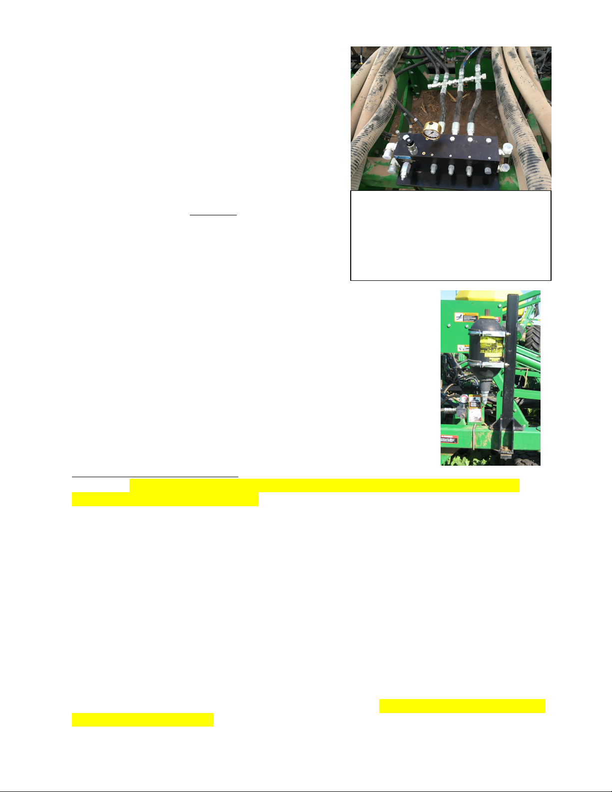
Installing the manifold (valve block), etc:
1) Locate bracket to secure UniForce manifold
(valve block) onto frame, and attach it to the
underside of valve block with 4 screws w/
countersunk heads (use blue Loctite,
provided). Set the bracket’s legs (bolts) over
the frame at the front-center of the drill.
Locate the bars that clamp the bracket into
position, slide them over the bracket’s stud
bolts, and then flange locknuts—do not
tighten yet.
2A) For air drills with 52 or fewer openers,
connect two of the four ¾" ports (the two with cartridges threaded into the front side—usually the
two closest to the gauge) on the rear of block to the ¾" feeder hoses going to the headers on the
center section’s ranks. There will be ‘equalizer’ fittings joining the feeder hoses (see Photo N).
Photo M. Note the ‘bridge’ hose between drill
sections in upper
-
left
of pic.
2B) For air drills with 53 – 76 openers, 3 cartridges & 3
rear ports are used (again, the rear ports being used
must correspond to where the cartridges are located).
The feeder hoses will again have additional equalizer
fittings that connect the 3 feeder hoses just rearward of
the valve block (see Photo N).
3) Using the UniForce manifold’s 1" ports on RH side
(‘RH’ when facing the direction of travel), screw in the
90º elbows, and then to the 165" x ¾" hoses that go to
the tractor, then into the high-flow male quick-coupler
tips (provided) + adaptors (provided). Tighten all
fittings. Zip-tie the long hoses as they run along the
drill’s tongue (large zip-ties provided).
4A) Unless your drill uses an updated JD Power
Beyond setup for the rockshaft, remove the EM hoses (leaving behind all
reducers and fittings in the EM valve block) that originally operated the
rockshaft. Using the LH ports (3/4") of the UniForce manifold, install the
reducer fittings, and then connect to the EM valve block using the ½" x
21" hoses (on tow-between drills, these will be longer). The upper port of
Exapta’s manifold goes to the lower port of the EM valve block (marked
‘V2’); lower port of Exapta’s valve block goes to the upper port of the
EM block (marked ‘V1’). Tighten all fittings.
4B) If your drill uses Power Beyond for the rockshaft, then keep
everything that runs it the same (UniForce will instead operate on a
separate remote). Plug the LH ports (3/4") of the UniForce manifold.
5) If an accumulator is being used: assemble it, mount it on the frame (see
photo), and connect it to the fittings that equalize the feeder hoses just behind the valve block
(don’t use the port on the valve block). The accumulator should arrive pre-charged, unless the
system was shipped by air. Pre-charge on accumulator should be 400 psi. Tighten all fittings.
6) Tighten the flange locknuts that hold the Exapta valve block’s bracket onto the frame.
7) if the in-cab pressure adjustment option is used, install it—see separate instructions.
8) if a tow-between cart is used, route the extra hoses thru it.
Securing the header hoses:
1) Slide the header hoses from side to side until the drop hoses and various fittings are in their best
location. Using the ‘clamping brackets’ (see Photo M), secure the header hose to the tray via the
5/16" hex-head bolts and flange locknuts (bolt head towards inside of tray). Use one clamping
brkt on far ends of each tray, and one in the middle of each wing tray (for 36-ft & larger drills),
and one in the middle of each center section. Tighten locknuts. The center-rear rank on CCS drills
is tethered entirely by zip ties—no clamping brackets are used.
Photo N. ‘Equalizer’ fittings joining the
feeder hoses. Photo shows a 60-ft with 72
openers, so 3 cartridges merge into 4
feeder hoses going out to the headers,
whereas on 3-section drills, only 2 feeders
go to the headers.

2) Fold up the wings carefully, making sure none of the bridge hoses get caught or pinched.
Adjust if necessary, or tether them away from the pinch points.
3) Use zip-ties to further secure the header hoses so they don’t slide around on the trays.
4) Attach warning tags to header hose. These are an important reminder to not crack any fittings
open until the pressure gauge reads zero. The UniForce system remains pressurized when openers
are in the ‘up’ position. Don’t assume you’ll always remember this—install the tags. Also,
someone else might be operating the drill, and try to repair something.
Prepare the system
Get all the air out of the lines! Cycle the system multiple times with at least one fitting per header
cracked open (preferably the ends of the header highest in elevation, or the farthest from the
manifold). You may also need to considerably loosen a fitting close behind the block itself. Note:
the pressurized hose should be the one going into the top port on RH side of UniForce manifold; if
not, reverse the hoses at the tractor remote. Even if the loose fitting behind the manifold isn’t
spurting a geyser of oil, the rest of the system should still slowly filling with oil—there’s a lot of
gallons involved, so be patient. You will need to add oil to the tractor during this process.
This is only the beginning, however, since these are single-action cylinders. What really needs to
happen is to collapse them (push the rod all the way in), and preferably on all of them at once.
This must be done while oil is flowing thru the headers. This is best done while going over a
sharp change in elevation with all the openers powered up—good examples would be the lip of a
waterway, or the edge of a crowned dirt or gravel road (terraces aren’t pointy enough at the top).
Another option might be to have the openers set down on a log or utility pole lying on the ground.
Even after doing this several times, there will still be air in the system, which may cause strange
things such as openers hanging up in the air. Keep working at getting the air out until all this
ceases. The more times you go over that jump in terrain (or a log) with the system powered up,
the sooner you’ll get all the air out and it will behave normally. Also, letting the oil cool down
completely (overnight) allows the remaining air bubbles to migrate upward where they can be
more easily purged when oil resumes flowing.

peration & adjustment
1) Adjust the knob for the rockshaft pressure to 2000+: it cannot lift the drill frame by itself
anymore. You want the rockshaft rolled over completely so that it’s sloped downward at the rear
by 15 – 20 degrees – it should remain in this position at all times during operation. Running the
rockshaft at 2000 – 3000 helps it to quickly overcome the resistance from the opener circuit
(which remains pressurized with openers up) when lowering the openers to begin the pass.
2) Adjust the knob for the opener pressure (the UniForce system) until you are maintaining a
reasonably uniform depth of cut. Running more than necessary, however, will cause sidewall
compaction. Common range is 800 – 1400.
3) If you’re drilling in steep terraces and the pressure on the opener circuit drops unacceptably
after the opener rank has passed over the terrace peak, this means that hydraulic flow is too low
which can be remedied by: 1) increasing the flow setting for that remote on the tractor (we prefer
setting it at max flow); 2) using a tractor with greater hydraulic capacity, 3) installing Exapta’s
accumulator for the UniForce system, 4) teeing two remotes together (especially useful on older
tractors).
4) Keep pressure on the cylinder circuit during transport, to prevent openers from flopping around
and causing damage to themselves, CCS tanks, or other structures.
Table of contents
Other Exapta Farm Equipment manuals


