Titan Attachments HRWDRAWBAR8 User manual
Other Titan Attachments Farm Equipment manuals

Titan Attachments
Titan Attachments 35TRANSPLANTR D User manual

Titan Attachments
Titan Attachments JD72RBFGGRAP User manual

Titan Attachments
Titan Attachments JDTS005V2 User manual

Titan Attachments
Titan Attachments JDHD60RAKE User manual

Titan Attachments
Titan Attachments 177CBUCKET User manual

Titan Attachments
Titan Attachments TORO35CBUCKET User manual
Titan Attachments
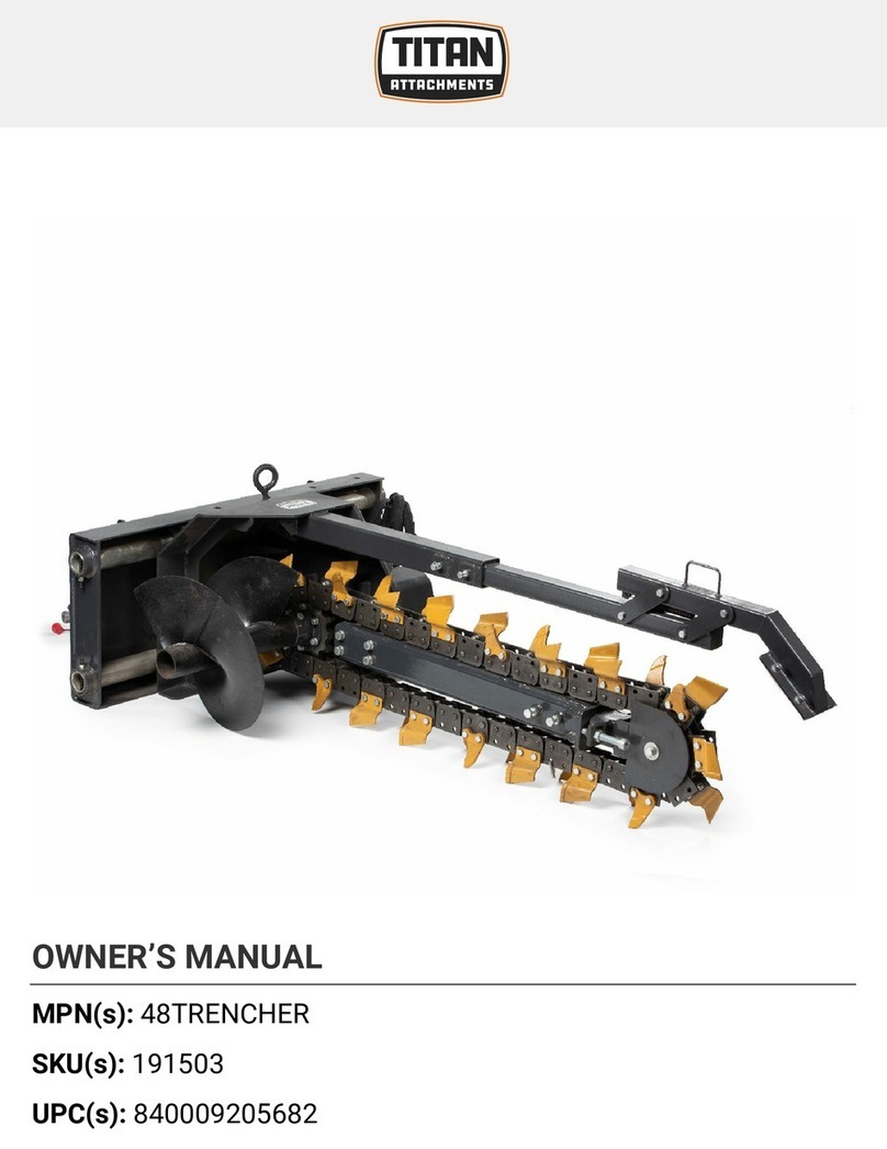
Titan Attachments 48TRENCHER User manual

Titan Attachments
Titan Attachments 3SHANKRIP User manual

Titan Attachments
Titan Attachments ROTIL48 User manual

Titan Attachments
Titan Attachments 72RBGRAP User manual

Titan Attachments
Titan Attachments 4ATVIRAKE User manual

Titan Attachments
Titan Attachments HD60RAKE User manual

Titan Attachments
Titan Attachments GJDHD72RAKE User manual

Titan Attachments
Titan Attachments LW48BUCKET User manual

Titan Attachments
Titan Attachments ADJDISCP2 User manual

Titan Attachments
Titan Attachments ATVLR4 User manual

Titan Attachments
Titan Attachments PRO Series User manual

Titan Attachments
Titan Attachments SS6DOZER72 User manual

Titan Attachments
Titan Attachments SSTRUSSBOOMv2 User manual

Titan Attachments
Titan Attachments 36TRENCHER User manual
Popular Farm Equipment manuals by other brands

Schaffert
Schaffert Rebounder Mounting instructions

Stocks AG
Stocks AG Fan Jet Pro Plus 65 Original Operating Manual and parts list

Cumberland
Cumberland Integra Feed-Link Installation and operation manual

BROWN
BROWN BDHP-1250 Owner's/operator's manual

Molon
Molon BCS operating instructions

Vaderstad
Vaderstad Rapid Series instructions


