Excel Tire Gauge PNEUTRONIC PNT-4 User manual
PNEUTRONIC PNT-4
DIGITAL AUTOMATIC TIRE GAUGE
INSTRUCTION MANUAL

When operating electrical equipment, basic precautions should always be followed,
including the following:
1. Read all instructions before installing and using this product.
2. Care must be taken as burns can occur from touching hot parts.
3. Do not operate equipment and place out of service if machine is damaged. Do not return to service
until equipment been examined by a qualied service person.
4. Users should follow the directions on the face of the machine.
5. This unit should not be operated by children.
6. This equipment is intended for motor vehicle use only.
7. To reduce the risk of re, do not operate equipment in the vicinity of open containers of ammable
liquids.
8. Keep hair, loose clothing, ngers and all parts of body away from moving parts.
9. Electrical circuit serving the equipment must be GFCI protected. Consult local and national codes
for installation and use.
10. Equipment should not be installed within 20 feet of fuel dispensing pumps. Consult local and
national codes for installation and use.
11. Unit contains a heater, so there may be hot surfaces in the unit.
12. Equipment must be securely fastened to a concrete pad prior to use.
13. Use only as described in this manual. Use only manufacture’s recommended attachments.
14. Always wear safety glasses and other appropriate personal protective equipment when servicing
the equipment.
15. While servicing the machine, with the exception of troubleshooting, the power should be
disconnected and properly locked out.
16. Ensure that tires are in suitable condition to be properly inated. Do not inate damaged tires.
Do not over inate tires.
17. If unit is equipped with the optional vacuum, do not pick up anything that is burning, such as
cigarettes, matches, or hot ashes. Do not use to pick up ammable or combustible liquids, such
as gasoline. Do not use without lters in place.
"SAVE THESE INSTRUCTIONS"
IMPORTANT SAFETY INSTRUCTIONS

1
ELECTRICAL REQUIREMENT
ELECTRICAL CONSUMPTION
ELECTRICAL FREQUENCY
MAXIMUM PRE-SET PRESSURE
MAXIMUM SUPPLY PRESSURE
AVERAGE AIR FLOW
ACCURACY
OPERATING TEMPERATURE
AIR RELATIVE HUMIDITY
( WITHOUT CONDENSATION )
WEIGHT
127 VAC +/- 10%
230 VAC +/- 10%
12 VDC +/- 10%
10 W
50 / 60 Hz
145 psi. - 10 Bar
175 psi. - 12 Bar
0.5 m3/min - 17.7 ft3/min
< 1% F.S.
14o- 122o F ( -10o- 50o C )
0 - 95%
1.7 Kg / 3.8 Lbs
TECHNICAL SPECIFICATIONS

INSTALLATION
2
2.1 Before installing the inlet air supply hose, ensure that the airline is free of any
contaminantsbysucientlyblowingoutthelinepriortoconnection.
Alteredairsupplyisrecommended.Thesupplypressureshouldnotexceed
175 psi.
2.2 Securetheinletandoutlethosestotheconnectorswithhoseclamps.
2.3 Fastenthegaugeviatheprovidedmountingholestoasuitablesurfacewith
appropiate anchors.
2.3 Connectthepowercordtoasuitableelectricalreceptacle.
INLETOUTLET
3
4
TECHNICAL SPECIFICATIONS
MAINTENANCE
3.1 Set pressure using the +and
-
buttons.
3.2 Connect chuck to tire valve stem.
3.3 Waitforthetiregaugeto“beep”indicatingthat
setpressurehasbeenreached.
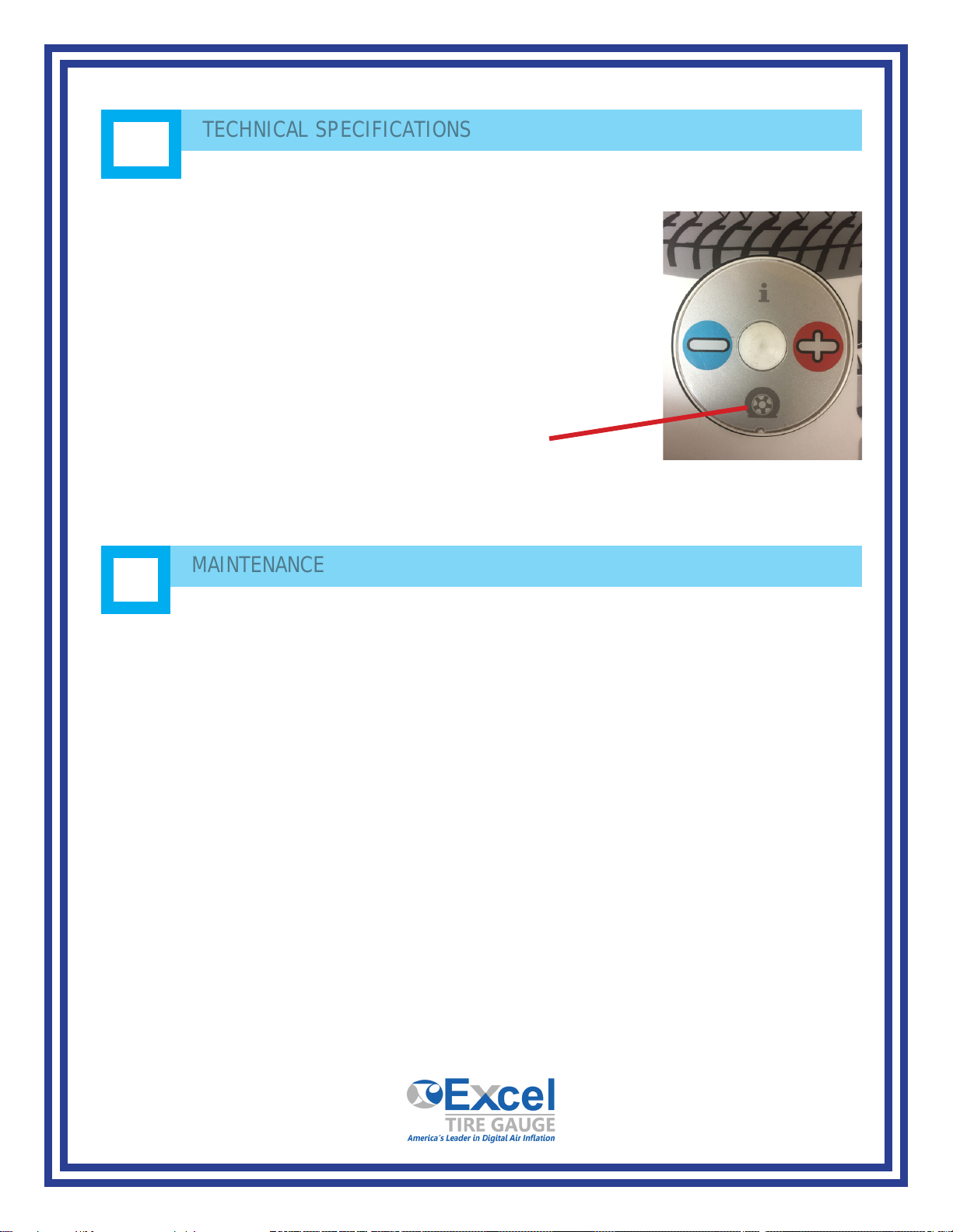
3.4 Intheeventthatthetireisat,presstheattire
button to begin the infation process
4.1 Neverallowinletpressuretoexceed175psi.
4.2 Use only an “OPEN END” chuck.
4.3 Ensure that the air supply is free of contaminants.
4.4 ThePNT4canbewipeddownwithsoapandwater.

5
TROUBLESHOOTING
5.1 DisplayreadsEr1,Er2,Er4,orEr8-Removechuckfromtire,resetthepower.
If the problem continues, contact service.
5.2 Blankdisplay-checkthepowersupply.
5.3 Ifaconstantairleakisnoticedduringtheinitialstartupoftheunit,checkto
ensurethattheinletandoutlethoseswerenotreversedwhenconnectedtothe
gauge.
5.4 DisplayreadsEr3-Checkthesupplyairforadequatepressure.Ifproblem
persists,cleantheinletlterlocatedundertheinlethoseconnector.
5.5 DisplayreadsEr5-Verifythatthepowersupplyisthesameasrequiredbythe
equipment.
5.6 DisplayreadsEr7-Verifythatthechuckisnotcloggedandthatitisan
“openend”chuck.Er7willalsoappearifchuckstaysconnectedtothetirefor
longerthan15secondsafteritisinated.
5.7 Ifthegaugedoesnotreachthedesiredpressure,anddisplaysahigherorlower
value, look for air leaks from the hose or connections.
5.8 Ifcalibrationtimeseemsexcessive,cleanairlterandcheckairlinefor
obstructions.
5.9 Ifthegaugedoesnotperformcalibration,pushthe“attire”buttonifthetireis
deated,orreplacechuck.
5.10 Ifgauge“beeps”whenchuckisnotconnectedtoatire,verifythatthechuckis
notcloggedandthatitisa“openend”chuck.
5.11 If it appears that the gauge is functioning by itself continuously, verify that the
chuckisnotcloggedandthatitisa“openend”chuck.

WARRANTY
All parts, excluding hose and hose chucks, have one year limited warran- ty from date of purchase
(Outside labor is not covered).
Excel requires that the customer calls into our Technical Support Dept. to troubleshoot the problem
rst before shipping any parts back to us under warranty.
Contact Info: Phone: 401-732-8420
Toll Free: 1-866-455-8768
Oce hours:
Monday - Friday 8:00AM – 4:30 PM (EST)
Aer troubleshooting the problem and warranty is validated, our Tech- nical Support Rep. will
issue a RMA # (Return Merchandise Authorization) for the defected part(s) to be returned.
Defective parts should be sent to Excel along with serial number of the machine, installation date,
and problem. With a black marker, make sure to write the RMA # on the outside of the box.
Once the defected part has been received, a new or repaired part will be sent back free of charge
via ground freight. Expedited freight is at an addi- tional cost.
Note: Freight cost is not included when shipping the defected part back. .
Important: Use of this product in any way not stated in this manual can compromise safety
features of this product.
6
WARRANTY
Excel Tire Gauge, LLC.
215 Jeerson Blvd, Warwick, RI 02888
Tel: 401 732 8420 Fax: 401 384 6157
WWW.EXCELTIREGAUGE.COM
Table of contents


