EXEL ACOUSTICS tecnare TPB1U User manual

Keep these important operating instructions.
Check www.tecnare.com for updates.
Operation Manual
Accessories
TPB1U Connection Panel
Version1.1


General Information
TPB1U Operation Manual
Ver.: 1.0_UK/ES 03/2021
©EXEL ACOUSTICS SL; all right reserved
The information contained in this manual has been carefully
checked for accuracy, at the time of going to press, however
no guarantee is given with respect to the correctness.
Exel Acoustics SL accepts no responsibility for any errors or
inaccuracies that may appear in this manual or the products
and software described in it. Technical specications, dimen-
sions, weights and properties do not represent guaranteed
qualities. As manufacturers we reserve the right to make
alterations and modications within the framework of legal
provisions, as well as changes aimed at improving quality.
EXEL ACOUSTICS SL
CL Encinar, 282 – Pol. Ind. Monte Boyal
45950 Casarrubios del Monte (Toledo) Spain
Phone: (+34) 918 170 110 Fax:
4
Operation Manual
www.tecnare.com
IMPORTANT SAFE INSTRUCTIONS
Before using our product, be sure to carefully read the manual and safe Instructions. Keep this document with the device
all time.
1. Read these instructions
2. Keep these instructions.
3. Heed all warnings.
4. Follow all SAFETY INSTRUCTIONS as well DAN-
GER and OBLIGATION warnings.
5. Only use attachments / accessories specied by Exel
Acoustics SL.
6. Do not use this apparatus near water.
7. Clean only with dry cloth.
8. Do not block any ventilation openings. Install in ac-
cordance with Exel Acoustics’ instructions.
9. Do not install near any heat sources such as radi-
ators, heat registers, stoves or other apparatus (in-
cluding ampliers) that produce heat.
10. Do not defeat the safety purpose of the polarized or
grounding type plug. A polarized plug has two blades
with one more wide than the other. A grounding type
plug has two blades and a third pin are provided for
your safety. If the provided plug does not t into your
outlet, consult an electrician for replacement of the
obsolete outlet.
11. Protect the power cord from being walked on or
pinched particularly at plugs, convenience recepta-
cles and the point where they exit from the appara-
tus.
12. Unplug this apparatus during lightning storms or
when unused for long periods of time.
13. Refer all servicing to qualied service personnel. Ser-
vice is required when the apparatus has been dam-
aged in any way, such as power-supply cord or plug
damaged, liquid has been spilled or objects have
fallen into the apparatus, this apparatus has been ex-
posed to rain or moisture, does not operate normally,
or has been dropped.
14. Use the mains plug to disconnect the device from
mains.
15. Do not expose this equipment to dripping or splash-
ing and ensure that no objects lled with liquids, such
as vases, are placed on the equipment.
16. The mains plug of the power supply cord shall remain
readily operable.
17. Do not connect the unit’s output to any other volt-
age source, such as battery, mains source, or power
supply, regardless of whether the unit is turned on
or off.
18. Do not remove the top (or bottom) cover. Removal of
the cover will expose hazardous voltages. There are
no user serviceable parts inside and removal may
void warranty.
19. If the equipment is used in a manner not specied by
the Exel Acoustics, the protection by the equipment
may be impaired.
CAUTION: To reduce the risk of re of electric
shock, do not expose this device to rain or mois-
ture.
CAUTION: Do not remove any covers, loosen any
xings or allow items to enter any aperture
CAUTION: The rear of the product may get hot.
Avoid direct skin contact during operation and for
at least 5 minutes after power has been isolated.
CAUTION: The product must only be positioned at
oor level when operated in a horizontal position.
5
Operation Manual
www.tecnare.com
PRECAUCIÓN:Para reducir el riesgo de incendio
por desgarga eléctrica, no exponga este aparato a
la lluvia o a la humedad.
PRECAUCIÓN: No retire la cubiert, aoje tornillos o
permita la entrada de elementos por ninguna aber-
tura
PRECAUCIÓN: La parte trasera del equipo puede
calentarse. Evite el contacto directo con la piel du-
rante su funcionamiento y durante, al menos, 5 mi-
nutos después de que se haya apagado
PRECAUCIÓN: El equipo solo debe colocarse en el
suelo cuando se opera en posición horizontal.
Antes de usar este producto, asegúrese de leer cuidadosamente el manual y las instrucciones de seguridad.
1. Lea estas instrucciones.
2. Conserve estas instrucciones.
3. Respete y siga todas las advertencias.
4. Siga todas las INSTRUCCIONES DE SEGURIDAD,
así como las advertencias de PELIGRO y OBLIGA-
CIÓN.
5. Utilice solo accesorios autorizados por Exel Acous-
tics SL.
6. No use este aparato cerca del agua.
7. Limpiar solo con un paño seco.
8. No bloquee las aberturas de ventilación e intalar de
acuerdo con las instrucciones de Exel Acoustics.
9. No instale el aparato cerca de fuentes de calor tales
como radiadores, calefactores estufas u otros apara-
tos que produzcan calor.
10. Esta unidad debe ser conectada mediante un cable
de alimentación de 3 hilos. Por razones de seguri-
dad, LA CONEXIÓN A TIERRA NO DEBE DESCO-
NECTARSE EN NINGUNA CIRCUNSTANCIA.
11. Proteja el cable de alimentación de ser pisado o
aplastado, especialmente los enchufes, receptáculos
y en el punto en el que salen del aparato.
12. Desconecte este aparato durante tormentas eléctri-
cas, terremotos o cuando no vaya a emplearse du-
rante largos periodos.
13. Confíe las reparaciones a personal cualicado. Se
requiere servicio cuando el aparato ha sido dañado
de alguna manera como por ejemplo si el cable de
alimentación o el enchufe está dañado, se ha derra-
mado líquido o han caido objetos dentro del aparato,
el aparato ha sido expuesto a lluvia o a la humedad,
no funciona con normalidad o se ha caído.
14. Desconecte completamente este aparato de la red
eléctrica desconectando el cable de alimentación.
15. No exponga este equipo a salpicaduras ni coloque
sobre él objetos que contengan líquidos, tales como
vasos o botellas. Equipo IP20.
16. El enchufe o la conexión a red debe ser facilmente
accesible.
17. No conecte la salida de la unidad a ninguna otra
fuente de voltaje, como batería o fuente de alimen-
tación independientemente de si la unidad está en-
cendida o apagada.
18. No retire la cubierta superior (o inferior). La retirada
de la cubierta lo expondrá a voltajes peligroso. No
hay piezas reparables por el usuario en el interior y
su extracción podría anular la garantía.
19. Si el equipo se utiliza de la forma no especicada por
Exel Acoustics, la protección del equipo puede verse
afectada.
IMPORTANTES INSTRUCCIONES DE SEGURIDAD
6
Operation Manual
www.tecnare.com
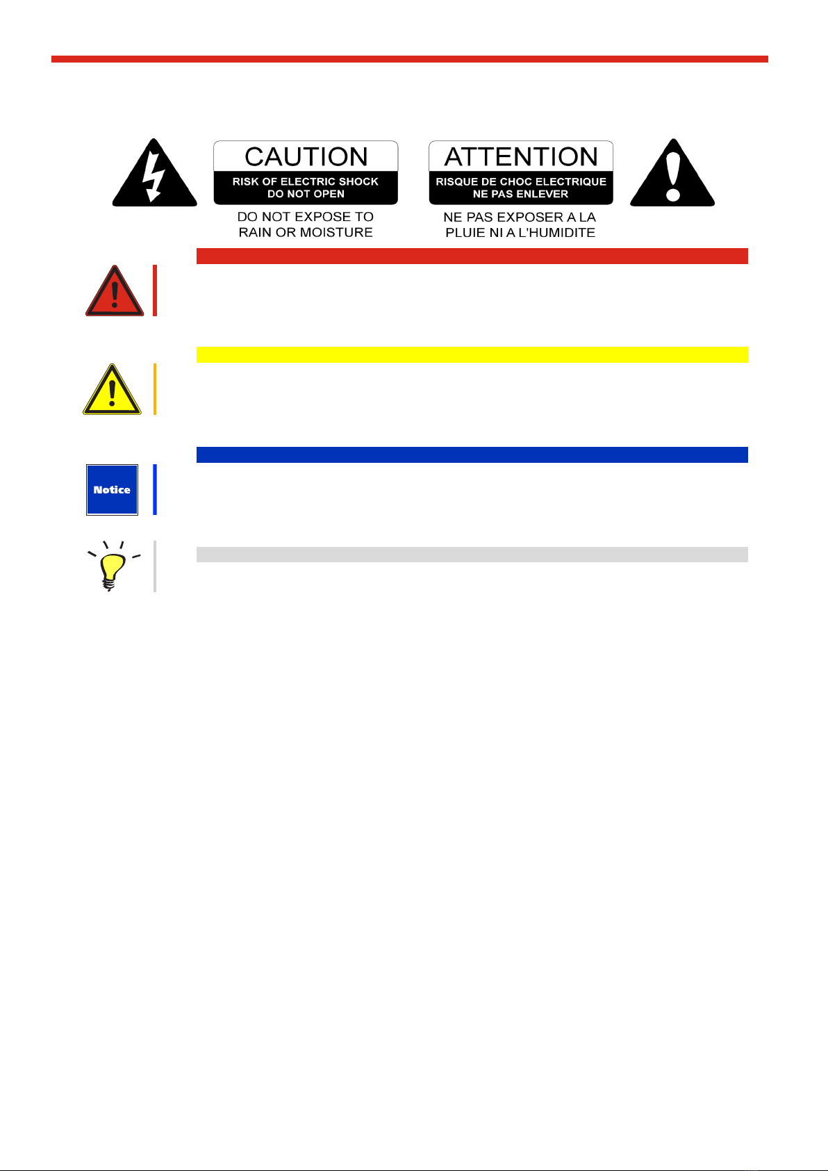
SYMBOL USED / SÍMBOLOS USADO
warning
caution
notice
tip or pointer
This simbol indicate Risk of injury. It is essential to observe this warning. Non-compliance can lead to serious
injury or death.
Este símbolo indica Riesgo de lesiones. Es fundamental observar esta advertencia. Su incumplimiento puede
provocar lesiones graves o la muerte.
This simbol indicate Personal injuries. It is essential to observe this warning. Non-compliance can lead to minor
or slight injury.
Este símbolo indica Lesiones personales.Es fundamental observar esta advertencia. Su incumplimiento puede
provocar lesiones leves.
This simbol indicate Damage to the devices or environment. It is essential to observe this warning. Non-compli-
ance can lead to damage to property or equipment or environmental damage.
Este símbolo indica Daños a los dispositivos o al medio ambiente. Es fundamental observar esta advertencia.
Su incumplimiento puede provocar daños al equipo o daños al medio ambiente.
This simbol indicate information that contributes to better understanding.
Este símbolo indica Información que contribuye a una mejor comprensión del producto.

7
Operation Manual
www.tecnare.com
STANDARDS
FOR CUSTOMERS IN EUROPE
This product complies with both the LVD (electrical safety) 73/23/EEC and EMC (electromag-
netic compatibility) 89/336/EEC directives issues by the commission of the European commu-
nity.
Compliance with these directives implies conformity with the following European standards:
EN60065 Product safety
EN55103-1 EMC emissions
EN55103-2 EMC immunity
This product is intended for the following electromagnetic environments: E1, E2; E3 & E4.
Este producto cumple con las directivas LVD (seguridad eléctrica) 73/23 / EEC y EMC (compatibilidad electro-
magnética) 89/336 / EEC emitidas por la comisión de la comunidad europea.
El cumplimiento de estas directivas implica la conformidad con las siguientes normas europeas:
EN60065 Seguridad del producto
EN55103-1 Emisiones EMC
EN55103-2 inmunidad EMC
Este producto está diseñado para los siguientes entornos electromagnéticos: E1, E2; E3 y E4.
THIS PRODUCT MUST BE EARTHED. Use only a exible cable or cord with a green and yellow core which
must be connected to the protective earthing terminal of a suitable mains plug or the earthing terminal of the
installation. The cord must be a maximum of 2m long, have a 4mm2 CSA, a 300/500V rating and comply with
EN50525-2-11 / H05W-F.
THIS PRODUCT IS DESIGNED FOR PERMANENT INSTALLATION. It must be tted in to a 19” rack enclosu-
re and not operated unless so installed. The rack enclosure should be open at the front and back to allow free
ventilation and movement of air through the product.
ESTE PRODUCTO DEBE CONECTARSE A TIERRA. Utilice únicamente un cable exible o cordón con un nú-
cleo verde y amarillo que debe conectarse al terminal de tierra de protección de un enchufe de red adecuado o
al terminal de tierra de la instalación. El cable debe tener un máximo de 2 m de largo, tener una CSA de 4 mm2,
una clasicación de 300/500 V y cumplir con EN50525-2-11 / H05W-F.
ESTE PRODUCTO ESTÁ DISEÑADO PARA UNA INSTALACIÓN PERMANENTE. Debe instalarse en un ar-
mario de rack de 19” y no debe utilizarse a menos que esté instalado. El armario debe estar abierto en la parte
delantera y trasera para permitir la ventilación y el movimiento del aire a través del producto.
FOR CUSTOMERS IN THE USA
This product has been tested for electrical safety and complies with UL60065 7th edition
THIS PRODUCT MUST BE EARTHED. Use only a exible cable or cord with a green or green / yellow core which
must be connected to the protective earthing terminal of a suitable mains plug or the earthing terminal of the ins-
tallation. The cord must be a maximum of 6’ long, be 12AWG, have a rating SJ, SJT, SJE or 300/500V H05W-F
and be marked VW-1.
THIS PRODUCT IS DESIGNED FOR PERMANENT INSTALLATION. It must be tted in to a 19” rack enclosure
and not operated unless so installed. The rack enclosure should be open at the front and back to allow free ven-
tilation and movement of air through the product.

8
Operation Manual
www.tecnare.com
FOR CUSTOMERS IN THE CANADA
This product complies with CA /CSA C22.2 No.60065-03
Ce produit est conforme avec CA /CSA C22.2 No.60065-03
THIS PRODUCT MUST BE EARTHED. Use only a exible cable or cord with a green or green / yellow core which
must be connected to the protective earthing terminal of a suitable mains plug or the earthing terminal of the installa-
tion. The cord must be a maximum of 6’ long, be 12AWG, have a rating SJ, SJT, SJE or 300/500V H05W-F and be
marked VW-1.
CE PRODUIT DOIT ÊTRE MIS À LA TERRE. Utilisez uniquement un câble souple avec un noyau vert ou vert / jaune
qui doit être relié à la borne de terre de connecteur d’alimentation ou la borne de terre de l’installation. Le cordon
doit être un maximum de 6’ (2m) de long, 12 AWG (2.5mm2 CSA), être classé SJ, SJT, SJE ou 300/500V H05W-F
et être marquée VW-1.
THIS PRODUCT IS DESIGNED FOR PERMANENT INSTALLATION. It must be tted in to a 19” rack enclosure and
not operated unless so installed. The rack enclosure should be open at the front and back to allow free ventilation
and movement of air through the product.
CE PRODUIT EST CONÇU POUR UNE INSTALLATION PERMANENTE. Il doit être installé dans un boîtier rack
19-in. Le rack devrait être ouvert à l’avant et l’arrière pour permettre la ventilation et le mouvement d’air libre à travers
le produit .
DECLARATION OF CONFORMITY WITH CANADIAN ICES-003
This Class B digital apparatus complies with Canadian ICES-003.
Cet appareil numérique de la classe B est conforme à la norme NMB-003 du Canada.

9
Operation Manual
www.tecnare.com
EXEL ACOUSTICS SL
CL Encinar, 282. Polígono Industrial Monte Boyal. 45950 – Casarrubios del Monte (Toledo), España (Spain).
Declara que el accesorio TPB1U y sus respectivas opciones, cumple con los objetivos de las Directivas:
Declare under our sole responsibility that the TPB1U accessorie product comply with relating Directives:
(1) Directiva de Baja Tensión - 2014/35/UE
(2) Directiva de Compatibilidad Electromagnética - 2014/30/UE
(3) Directiva RoHS - 2011/65/UE
(4) Directiva RAEE - 2012/19/UE
(1) Low Voltage Directive 2014/35/EU
(2) EMC 2014/130/EU
(3) RoHS Directive 2011/65/EU
(4) WEEE Directive 2012/19/EU
Y es conforme a las siguientes Normas Armonizadas Europeas:
In compliance with these Harmonized European Norms:
(1) EN60065 8th. Audio, video and similar electronic apparatus. Safety requirements.
(2) EN55032:2012. EMC emissions & immunity.
(3) EN55035-2017
DECLARACIÓN DE CONFORMIDAD
DECLARATION OF CONFORMITY

10
Table of Contents
www.tecnare.com TPB1U Connection Panel Board | rev.:1.0
TPB1U
Table of Contents
IMPORTANT SAFE INSTRUCTIONS ________________________________________________________ 4
IMPORTANTES INSTRUCCIONES DE SEGURIDAD ___________________________________________ 5
SYMBOL USED / SÍMBOLOS USADO _______________________________________________________ 6
STANDARDS___________________________________________________________________________ 7
DECLARACIÓN DE CONFORMIDAD _______________________________________________________ 9
DECLARATION OF CONFORMITY _________________________________________________________ 9
1. Introduction and unpacking / Introducción y desembalado ______________________________________ 11
1.1. Welcome to Tecnare / Bienvenido a Tecnare________________________________________ 11
1.2. Unpacking / Desembalado ______________________________________________________ 11
2. Product Description / Descripción del Producto ______________________________________________ 13
3. Front and Back View. Connectors and Functions /Panel Frontal y Trasero. Conectores y Funciones _____ 13
3.1. Front / Frontal _______________________________________________________________ 13
3.2. Back / Panel posterior _________________________________________________________ 14
4. AES3 Link ___________________________________________________________________________ 17
5. Technical Specications / Especicaciones__________________________________________________ 18

11
Introduction
www.tecnare.comTPB1U Connection Panel Board | rev.:1.0
TPB1U
1. Introduction and unpacking / Introducción y desem-
balado
1.1. Welcome to Tecnare / Bienvenido a Tecnare
Thank you for choosing a Tecnare®TPB1U connector panel “Made in Spain” for your aplication.
Please spare a little time to study the contents of this manual, so that you obtain the best possible
performance from this unit.
All Tecnare®products are carefully engineered for world-class performance and reliability.
If you would like further information about this or any other Tecnare®product, please contact us. We
look forward to helping you in the near future.
As part of a continuous evolution of techniques and standards, Exel Acoustics SL as manufacturer
of Tecnare® products reserve the right to change the specications of its products and the content of its docu-
ments without prior notice.
Gracias por elegir el panel de conexión Tecnare® TPB1U, “Fabricado en España”.
Dedique un poco de tiempo a estudiar el contenido de este manual, de modo que obtenga el mejor rendimiento
posible de esta unidad.
Todos los productos Tecnare® están cuidadosamente diseñados para brindar un rendimiento y una conabili-
dad de primer nivel.
Si desea obtener más información sobre este o cualquier otro producto Tecnare®, comuníquese con nosotros.
Esperamos poder ayudarlo en un futuro próximo.
Como parte de una continua evolución de técnicas y estándares, Exel Acoustics SL como fabricante de produc-
tos Tecnare® se reserva el derecho de cambiar las especicaciones de sus productos y el contenido de sus documentos
sin previo aviso.
Updates and supplementary information are available on the Tecnare®website / Las actualizaciones
de productos e información complementaria, están disponibles en nuestra web:
http://www.tecnare.com
Tecnare Technical Support is available at:
• (T): +34 918 170 110 - +34 918 171 001
Thank you again for placing your condence in Tecnare®products. Gracias de nuevo por depositar su conan-
za en productos Tecnare®.
1.2. Unpacking / Desembalado
After unpacking the unit please check carefully for damage. Every Tecnare product is tested and
inspected before leaving the factory and should arrive in perfect condition. If damage is found, please notify the
carrier concerned at once. You, the consignee, must instigate any claim. Please retain all packaging in case of
future re-shipment.

12
Introduction
www.tecnare.com TPB1U Connection Panel Board | rev.:1.0
TPB1U
Después de desembalar la unidad, compruebe cuidadosamente si hay daños. Todos los productos
Tecnare se prueban e inspeccionan antes de salir de fábrica y deben llegar en perfectas condiciones. Si se encuen-
tran daños, notique al transportista en cuestión de inmediato. Usted, el destinatario, debe iniciar cualquier reclama-
ción. Conserve todo el embalaje en caso de reenvío futuro

13
Product Description
www.tecnare.comTPB1U Connection Panel Board | rev.:1.0
TPB1U
2. Product Description / Descripción del Producto
The TPB1U connector panel of Tecnare is a pro-grade
audio panel used as a solution for the wiring of am-
pracks, which should head for loudspeakers by a both,
four pin and/or eight pin SpeakON cabling
Output ports include 4 SpeakON®NL4 ports and
1 SpeakON®NL8, 4 XLR analog inputs, and 2 XLR
analog link ports. In addition, the system offers 1 AES3
inputs (1/2) and 1 AES3 link ports (1/2).
Ethernet communication is supported through 1 RJ45
port.
The length of the patch cables at the rear panel is 100
cm (39.4”).
In addition, it is completed with a front-side 32A Pow-
ercON® connector to bring AC power to the amplier.
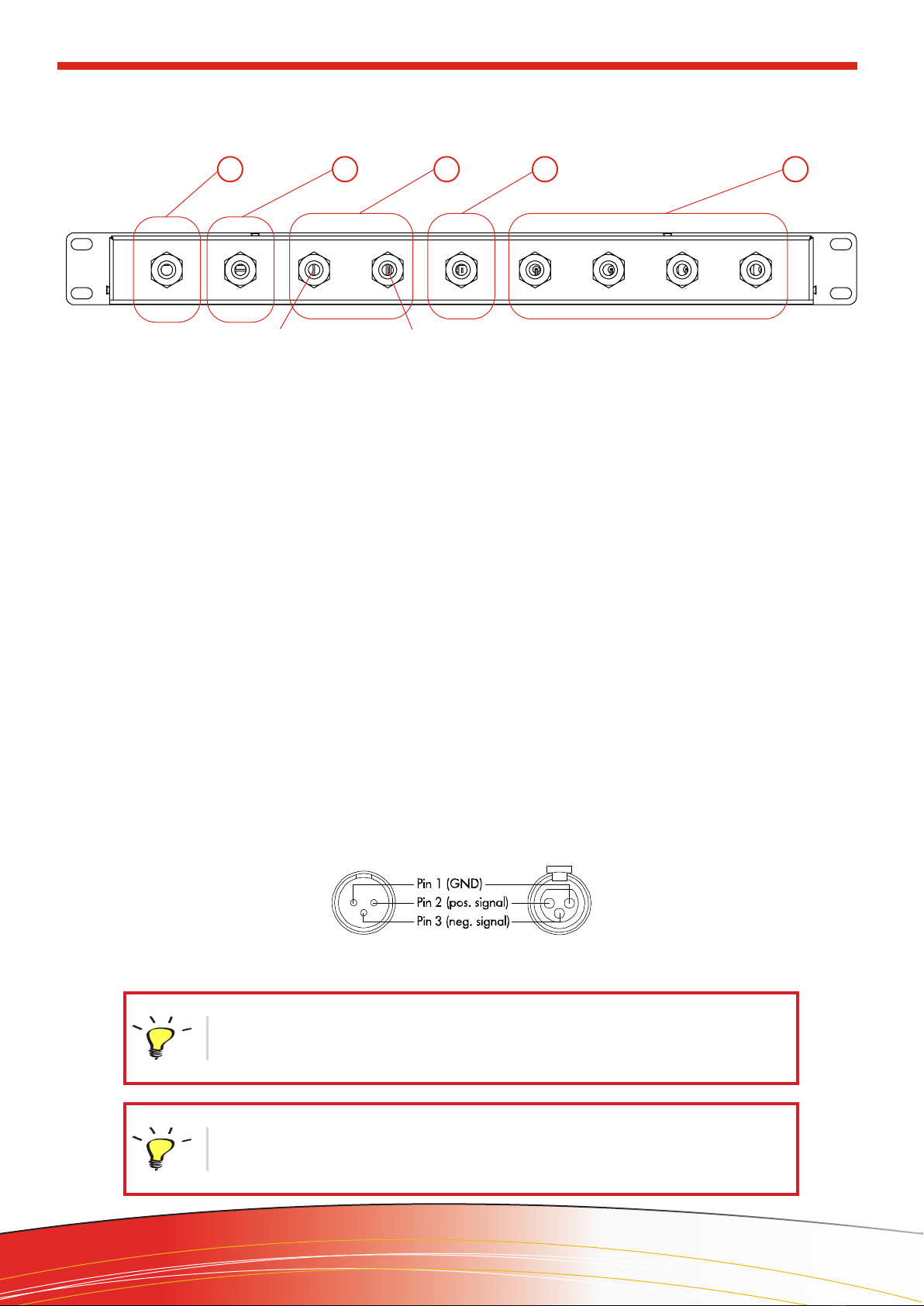
1. Analog INPUT 1 to 4 (XLR) & Analog Link 1
and 2 .
2. AES3 INPUT 1 and 2 (XLR). AES3 Link (XLR)
1 and 2.
3. Amplied Output (NL4) Channels 1 and 2.
4. Amplied Output (NL8) Channels 1 to 4.
5. Amplied Output (NL4) Channels 3 and 4.
6. ETHernet Communication Port
7. Main Power Inlet (PowerCON®32A)
1. Entrada analógica 1 a 4 (XLR) & salida puente
(XLR) 1 y 2 .
2. Entrada AES3 1 y 2 (XLR). Salida Puente
AES3 1 y 2 (XLR).
3. Salida amplicada (NL4) Canales 1 y 2.
4. Salida amplicada (NL8) Canales 1 a 4.
5. Salida amplicada (NL4) Canales 3 y 4.
6. Puerto de comunicación ETHernet
7. Entrada de alimentación (PowerCON®32A)
El TPB1U de Tecnare es un panel de conexión de au-
dio con calidad profesional que se utiliza como solu-
ción para el cableado de amplicadores en rack, que
deben dirigirse a los altavoces mediante un cableado
SpeakON®de cuatro u ocho pines.
Las salida incluyen 4 puertos SpeakON®NL4 y 1
SpeakON®NL8, 4 entradas XLR analógicas y 2 XLR
de puente analógico. Además, el sistema ofrece 1 en-
trada AES3 (1/2) y 1 XLR de puente AES3 (1/2).
Comunicación por red es posible a través de 1 puerto
RJ45.
La longitud de los cables de conexión en el panel pos-
terior es de 100 cm (39,4 “).
Además, se completa con un conector frontal Power-
CON® 32 A para llevar alimentación al amplicador.
3. Front and Back View. Connectors and Functions /Pa-
nel Frontal y Trasero. Conectores y Funciones
3.1. Front / Frontal
1
2
43 5
6 7
Analog 1 Analog 2 Analog 3 Analog 4 AES3 A-2 Way B-1 WayC -2 Way D-1 Way
ETHnet
AC MAIN
100-230V
IN A LINK AL INK B
IN B CH1: 1+/-
CH2: 2+/- CH2: 1+/-
TPB1U
IN C IN D IN LINK CH3: 1+/-
CH4: 2+/- CH4: 1+/-
4 Way
14
Product Description
www.tecnare.com TPB1U Connection Panel Board | rev.:1.0
TPB1U
3.2. Back / Panel posterior
Fig. 03: PIN out assignment Input/Link - Balanced connection / Asignación de pins - Concexión Balanceada
12345
1. Analog INPUT 1 to 4 (XLR)
2. AES3 INPUT 1 and 2 (XLR).
3. 3A) Channels 1/2; 3B Channels 3/4 (SpeakON®
NL4).
4. ETHernet (Cat5e).
5. Power cable 3x4mm2.
For each input channel there is a female XLR-
3 connector for analogue inputs. The Analog input A
and B also feature with a XLR-3 Male link connector
passively wired to the input connectors.
Para cada canal de entrada analógico hay un
conector XLR-3 hembra. Las entradas analógicas A y
B también cuentan con conectores de puente XLR-3
macho conectados pasivamente a los conectores de
entrada.
1. Entradas analógicas 1 a 4 (XLR)
2. Entrada AES3 1 y 2 (XLR).
3. 3A) Canales 1/2; 3B Canales 3/4 (SpeakON®
NL4).
4. ETHernet (Cat5e).
5. Cable de alimentación 3x4mm2.
3A3B
3.2.1. Analogue Input Connections / Conexiones de entrada Analógicas
The assignments pin of this XLR-3 / La asignación de pins de estos XLR-3 es:
The HOT, + or ‘in phase’ connection should be made to pin 2 of the XLR connector.
The COLD, - or ‘out of phase’ connection should be made to pin 3 of the XLR connector.
Pin 1 of the XLR connectors is connected to the GND/Shield.
La conexión “caliente”, “+” o “en fase” debe realizarse en el pin 2 del conector XLR.
La conexión “fria”, “-” o “fuera de fase” debe realizarse en el pin 3 del conector XLR.
El pin de los conectores XLR está conectado a GND.
Please note: The use of unbalanced connections is not recommended, however, in case
of connecting it to unbalanced source the signal should be connected to the XLR pin
2. The Cold or cable screen should be connected to XLR pin 1 with a short connection
made between pin 3 and pin 1.
Tenga en cuenta: No se recomienda el uso de conexiones no balanceada, sin embargo,
en caso de hacerlo a una fuente no balanceada, la señal debe conectarse al pin 2 del
XLR. La conexión “fría” o cable apantallado, debe conectarse al pin 1 del XLR con una
conexión entre los pines 1 y 3.
15
Product Description
www.tecnare.comTPB1U Connection Panel Board | rev.:1.0
TPB1U
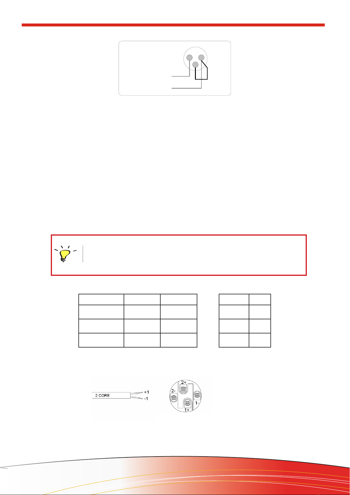
Amp Out 1 += 1+
Amp Out 1 -= 1 -
NL4 Mono-amplified connection
2 1
3
Pin 2 HOT +
Pin 1 Shield
Input XLR unbalanced connection
Fig. 04: Balanced to Unbalanced Analogue wiring and PIN out / Cableado desbalanceado analógico
Fig. 05
The TPB1U is tted with four SpeakON®NL4
connector and one SpeakON NL8 connector. With
the help of the two back 4-wire speaker cables can
be supplied to the device by up to 4 amplier output.
The Speaker output ports 1 & 3 deliver 2-channels sig-
nals. This can be useful for making a connection to two
loudspeakers with one 4-core cable (i.e. Bi-amp). The
Speaker output port NL8 delivers 4-channels signals.
This allows for implementing system cabling with up
8-core speaker cables.
Each connector follows the next pin assignment. / Los conectores tienen la siguiente asignación de pines:
El TPB1U está equipado con cuatro conecto-
res SpeakON®NL4 y un conector SpeakON NL8. Por
medio de los dos cables de altavoz traseros de 4 hilos
se pueden suministrar al dispositivo hasta 4 salidas de
amplicador. Las salidas de altavoz 1 y 3 entregan se-
ñales de 2 canales. Esto puede resultar útil para rea-
lizar la conexión de dos altavoces con un cable de 4
hilos (es decir, biamplicados). El conector NL8 entre-
ga señales de 4 canales. Esto permite implementar el
cableado del sistema con cables de altavoz de hasta 8
hilos.
When using 2-channel speaker systems, ensure correct channel assignment as well as
appropriate connection to the amplier module.
Cuando use sistemas de altavoces de 2 canales, asegúrese de que la asignación de
canales sea correcta, así como la conexión al amplicador.
3.2.2. Audio Loudspeaker port / Salidas de Audio de altavoces
OUT A (2-way) 1+/ - = Ch A 2+/- = Ch B
OUT B (1-way) 1+/ - = Ch B
OUT C (2-way) 1+/ - = Ch C 1+/ - = Ch D
OUT D (1-way) 1+/ - = Ch D
NL4 CONNECTORS
PIN 1 +/- Ch A
PIN 2 +/- Ch B
PIN 3 +/- Ch C
PIN 4 +/- Ch D
NL8 CONNECTOR
16
Product Description
www.tecnare.com TPB1U Connection Panel Board | rev.:1.0
TPB1U
3.2.3. AC Power Connection / Conexión de CA
The TPB1U must always be connected using a 3-wire, grounded AC supply. The unit should never
be operated unless the AC power cable ground is correctly terminated; this is important for personal safety and for
control of the system grounding.
The device is supplied with a Neutrik PowerCon®32 type locking AC power connector. Use only an
AC power cord with a correctly terminated PowerCon®type connector to make the connection to the mains power
supply.
El TPB1U siempre debe conectarse utilizando una fuente de CA de 3 cables con conexión a tierra.
La unidad nunca debe utilizarse a menos que la conexión a tierra del cable de alimentación de CA esté correctamen-
te terminada; esto es importante para la seguridad personal y para el control de la conexión a tierra del sistema.
El dispositivo se suministra con un conector de alimentación de CA de bloqueo tipo Neutrik PowerCon®32.
Utilice únicamente un cable de alimentación de CA con un conector tipo PowerCon®correctamente terminado para
realizar la conexión a la fuente de alimentación principal.
When using 2-channel speaker systems, ensure correct channel assignment as well as
appropriate connection to the amplier module.
Cuando use sistemas de altavoces de 2 canales, asegúrese de que la asignación de ca-
nales sea correcta, así como la conexión al amplicador.
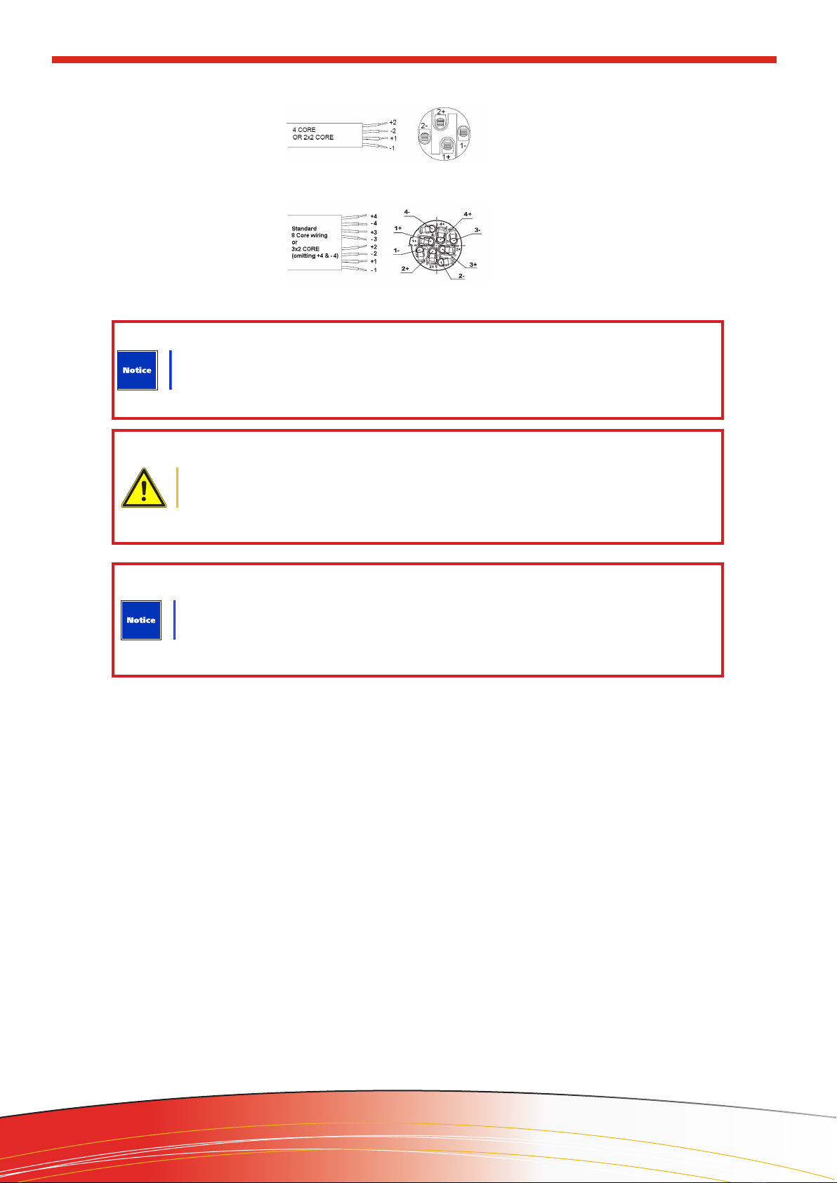
NL4 bi-amplified connection
NL8 Multi-amplified connection
Amp Out 1 += 1+
Amp Out 1 -= 1 -
Amp Out 2 += 2+
Amp Out 2 -= 2 -
Amp Out 1 += 1+
Amp Out 1 -= 1 -
Amp Out 2 += 2+
Amp Out 2 -= 2 -
Amp Out 3 += 3+
Amp Out 3 -= 3 -
Amp Out 4 += 4+
Amp Out 4 -= 4 -
The output of ampliers can produce a high voltage. Only use isolated loudspeaker cables
with correctly tted connectors. Do not connect or disconnect the loudspeaker/s while the
amplier is powered on.
La salidas de los amplicadores puede producir voltages peligrosos. Utilice únicamen-
te cables de altavoz aislados con conectores montados correctamente. No conecte ni
desconecte altavoces mientras el amplicador/res esté/en encendido/s.
Do not connect any loudspeaker enclosure, stage box or multi & Fan-out cable from a
2-way connector (1 & 3) of the TPB1U to a speakON connection where pins 1 and 2 are
joined. Otherwise, there a risk of damaging the loudspeaker component or the amplier.
No conecte nunca un altavoz, cajetín de escenario, o cable múltiple desde un conector
de 2-vias (1&3) del TPB1U a una conexión SpeakON donde se unan los pines 1 y 2. De lo
contrario, existe el riesgo de dañar el componente del altavoz o el amplicador.
Fig. 07

17
Product Description
www.tecnare.comTPB1U Connection Panel Board | rev.:1.0
TPB1U
4. AES3 Link
The AES3 Link ports are passively wired in parallel to the input ports. We recommend using these for a low
number of member units and with short leads only—for example, for a direct interconnection of 2–3 racks stacked.
The use of standard analog cable with AES3 will result in diminished performance. For best results, 110
ohm shielded twisted-pair cable for AES/EBU signals is highly recommended.
La concexion de unión AES3 está conectada pasivamente a la conexión de entrada. Recomendamos
utilizar esta conexión para un número limitado de unidades y solo con cables cortos., por ejemplo, una
interconexión directa de 2 o 3 rack apilados.
El uso de AES3 mediante cable analógico estandar reducirá el rendimiento de la conexión. Recomendamos
encarecidamente, utilizar un cable par trenzado de 110 ohm.
NOTE: Custom wiring should only be performed by qualied personnel.
Un cableado personalizado solo debe realizarse por personal cualicado.
1.
2.
3.
Slotted Screwdriver
Max. Torque 130 Ncm
1.
2.
3-pin Japan
NEMA L5-30P
3-pin South Korea
KS C8305
3-pin Australia
AS 3112
3-pin Brazil
NBR 14136
3-pin India
IS 1293
3-pin GB
BS 1363A
3-pin USA
NEMA L5-30P
3-pin South Africa
SANS 164-1
3-pin Argentina
IRAM 2073
3-pin Schuko
CEE 7/7
3-pin Denmark
IEC 60309
3-pin China
GB 2099
3-pin Swiss
SEV1011/T23
Wire Colour Attach to the Following
Terminal
European 50 Hz U.S. / Canada 60 Hz
Brown Black Hot or Live
Blue White Neutral (N)
Green &Yellow Green Protective earth / ground
(E or PE)
Fig. 08. Neutrik PowerCON32 Assembly
Fig. 09. Mains plug types and associated standard. (Graphics are no in scale) / Principlaes
tipos de conectores y su estandar asociado.

18
Specications
www.tecnare.com TPB1U Connection Panel Board | rev.:1.0
TPB1U
5. Technical Specications / Especicaciones
AUDIO I/O
Analogue Ports / Entradas Analógicas 4 x Analogue Input 1 to 4
2 x Analogue Link 1 & 2
AES3 1 INPUT ports (1/2)
1 LINK ports (1/2) (direct wiring)
Output Ports / Salidas 4 x Speakon NL4
1 x Speakon NL8
PHYSICAL
Height 1RU, 44mm
Width 19”, 482mm (front panel)
16.8”, 427mm (rear chassis)
Depth 184mm, 7.2” (behind rack)
Weight 3,5 Kgs, 7.7 pounds

19
www.tecnare.comTPB1U Connection Panel Board | rev.:1.0
TPB1U
Reinventing The Rules
©2021
Tecnare Sound Systems. All rights reserved.
TPB1U Operation manual
The contents of this manual are furnished for informational purposes only, are subject to change without notice, and should not
be construed as a commitment by Exel Acoustics SL. Exel Acoustics assumes no responsibility or liability for any errors or in-
accuracies that may appear in this manual. Except as permitted by applicable copyright law, no part of this publication may be
reproduced, stored in a retrieval system, or transmitted, in any form or by any means, electronic, mechanical, recording or other-
wise, without prior written permission from Exel Acoustics. Tecnare and PCC-Net are trademarks of Exel Acoustics SL. System
Engineer, BvNet and all third-party trademarks mentioned herein are the property of their respective trademark holders.
Printed in Spain.

rev. 1.0 2021
EXEL ACOUSTICS SL
CL Encinar, 282 - Pol. Ind. Monte Boyal
45950 Casarrubios del Monte (To)
Spain
www.tecnare.com - www.facebok.com/tecnare
(T): +34 918 170 110 - +34 918 171 001
(F): +34 918 183 053
Table of contents


