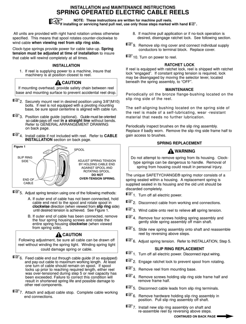
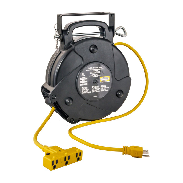
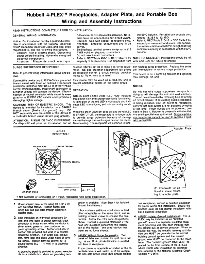
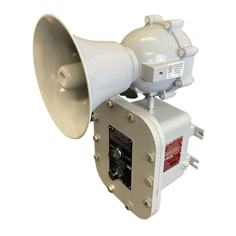
manuals.online logo
Brands
  1. Home
  2. •
  3. Brands
  4. •
  5. Hubbell
  6. •
  7. Cables And Connectors
  8. •
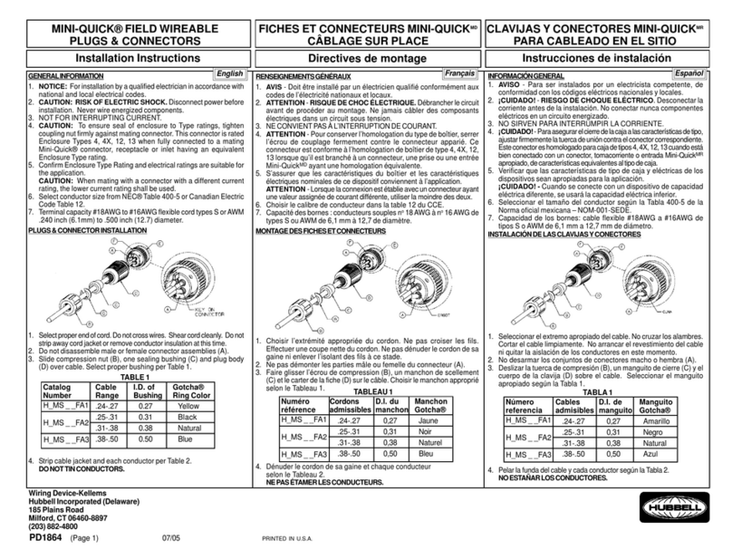
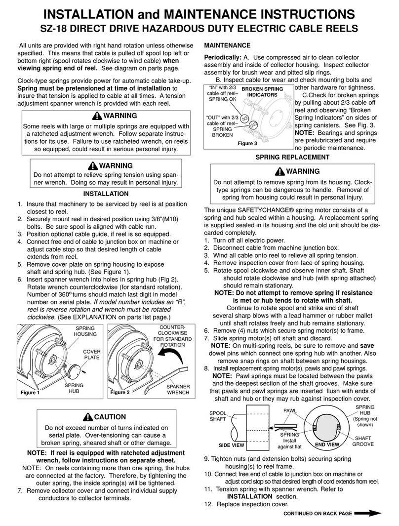
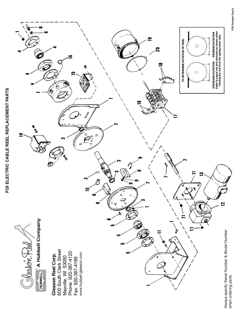
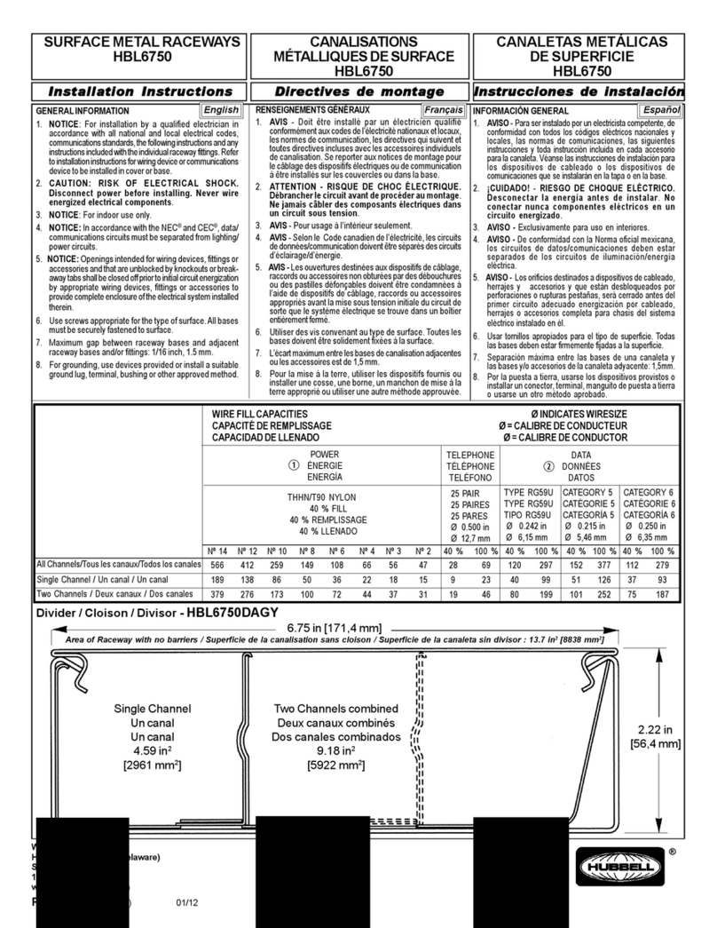
  9. Hubbell 16A User manual

Hubbell 16A User manual

PD1307 (PAGE1) PRINTED IN U.S.A. 02/98
Wiring Device-Kellems
Hubbell Incorporated (Delaware)
185 Plains Road
Milford, CT 06460-8897
(203) 882-4800
INSTALLATION INSTRUCTIONS
REPLACEMENT COVER ASSEMBLY
FOR HUBBELL RECEPTACLES AND
CONNECTORS
16A, 20A, 30A, 32A, 60A, 63A, 100A, 125A
DIRECTIVES DE MONTAGE
ENSEMBLE de COUVERCLE de
RECHANGE POUR LES PRISES et
CONNECTEURS de HUBBELL
16 A, 20 A, 30 A, 32 A, 60 A, 63 A, 100 A, 125 A
CONJUNTO de TAPA de RECAMBIO
PARA TOMACORRIENTES y
CONECTORES de HUBBELL
16 A, 20 A, 30 A, 32 A, 60 A, 63 A, 100 A, 125 A
INSTRUCCIONES DE INSTALACIÓN
ïï


IMPORTANT: BEFORE STARTING, PUT SAFETY GLASSES ON
IMPORTANT : METTRE DES LUNETTES DE SÉCURITÉ AVANT DE COMMENCER
IMPORTANTE : ANTES DE COMENZAR, COLOCARSE ANTEOJOS DE SEGURIDAD
Pasador de bisagra
Brazo de la tapa
Conjunto brazo-tapa
Orejas del pivote
Expulsor
Tomacorriente (con reborde) o conector
Resorte
Ranura para resorte en el dispositivo
(Tomacorriente o conector)
Axe de charnière
Bras du couvercle
Ensemble bras-couvercle
Pattes de pivot
Outil d'extraction
Prise (avec rebord) ou connecteur
Ressort
Rainure pour ressort gravée sur le dispositif
(Prise ou connecteur)
Hinge Pin
Cover arm
Arm & Cover Assembly
Pivot Ears of Device
Removal Tool
Receptacle (With Flange) or Connector
Spring
Spring-leg Groove on Device
(Receptacle or Connector)
HERRAMIENTAS NECESARIAS PARA EL MONTAJE
• Martillo • Prensa en «C»
• Pinza en punta de aguja • Anteojos de seguridad
TOOLS REQUIRED FOR ASSEMBLY
•Hammer • "C" Clamp
• Needle Nose Pliers • Safety Glasses
OUTILS NÉCESSAIRES AU MONTAGE
• Marteau • Presse en «C»
• Pince à bec fin • Lunettes de sécurité





INSTALLATION INSTRUCTIONS
1. Support Pivot Ears on device with “C” clamp before
driving out old Hinge Pin, as shown in Fig. 1. Using
Removal Tool supplied, drive out old Hinge Pin in
direction shown in Fig. 2 and remove old spring. Remove
“C” clamp.
DIRECTIVES DE MONTAGE
1. Soutenir les pattes de pivot avec la presse en «C» avant
d’extraire l’ancien axe de charnière, tel qu’illustré dans la
fig. 1. À l’aide de l’outil d’extraction fourni, extraire
l’ancien axe de charnière dans le sens illustré dans la fig.
2 et enlever l’ancien ressort. Enlever la presse en «C».
INSTRUCCIONES DE INSTALACIÓN
1. Sujetar las orejas del pivote sobre el dispositivo con una
prensa en «C» antes de sacar el antiguo pasador de
bísagra, como se indica en la Fig. 1. Empleando el
expulsor provisto, retirar el antiguo pasador de bisagra en
la dirección indicada en la Fig. 2 y quitar el antiguo
resorte. Retirar la prensa en «C».
Français Español
ï

ï



Fig. 2
Antiguo pasador de bisagra
Explusor
Dirección
Prensa en «C»
Resorte
Ancien axe de charnière
Extracteur
Direction
Presse en «C»
Ressort
Old Hinge Pin
Removal Tool
Direction
"C" Clamp
Spring
Fig. 1
English
LE LOT INCLUT
1 Ensemble bras-couvercle
1 Extracteur
1 Axe de charnière
1 ressort de charnière ou
EL EQUIPO INCLUYE
1 Conjunto brazo-tapa
1 Expulsor
1 Pasador de bisagra
1 Resorte de bisagra o
KIT INCLUDES
1 Arm & Cover Assembly
1 Hinge Pin Removal Tool
1 Hinge Pin
1 Hinge spring or
English Français Español
PD1307 (PAGE2) PRINTED IN U.S.A. 02/98
or
ou
o


Free Leg of Spring
New Spring Installed
Bent Leg of Spring in Hole
Leg of Spring Fixed on
Ledge of Arm
Removal tool
Cover
Extremo libre del resorte
Nuevo resorte instalado
Extremo acodado del resorte en el orificio
Extremo del resorte fijado sobre el reborde del brazo
Expulsor
Tapa
Extracteur
Extrémité libre du ressort
en position tendue
Removal Tool
Free Leg of Spring
in Rotated Position
Expulsor
Extremo libre del resorte
en posición de rotación
Explusor
Nuevo pasador de bisagra totalmente insertado
Extremo del resorte en la ranura
Removal Tool
Fully Inserted New Hinge Pin
Spring Leg in Groove
Extracteur
Nouvel axe de charnière en place
Extrémité du ressort dans la rainure
2. See Figure 3.
lnsert Removal Tool half way through new Arm of Arm
and Cover Assembly. Install spring over Removal Tool.
Fix one leg of spring on ledge of Arm, or insert 90° bent
leg of spring through hole In Arm whichever applies to the
particular Cover Assembly being installed. Continue
inserting Removal Tool so that it passes through both
pivot holes and is centered between arms.
3. See Figure 4.
With pliers, wind up free leg of spring approx. half a turn
and hold in position shown.
4. See Figure 5.
Position Arms of new Cover Assembly between Pivot
Ears of Connector or Receptacle and install free leg of
spring in groove provided on device. Line up holes in Arm
with holes in Pivot Ears. Push in new Hinge Pin (sup-
plied) in direction shown through Pivot Ears of device,
displacing Removal Tool. New Hinge Pin should be flush
to both Pivot Ears on device. Hammer and Removal Tool
may be used to fully assernble Hinge Pin.
2. Voir figure 3.
Insérer l’outil d’extraction à mi chemin dans le nouveau
bras de l’ensemble bras-couvercle. Placer le ressort sur
l’outil d’extraction. Appuyer une extrémité du ressort sur
la butée du bras ou insérer l’extrémité du ressort coudée
à 90º dans l’orifice du bras selon le type d’ensemble
bras-couvercle requis. Continuer à pousser l’outil
d’extraction vers l’intérieur du bras jusqu’à ce qu’il passe
à travers les deux orifices du pivot et soit centré entre
les bras.
3. Voir figure 4.
À l’aide de la pince à bec fin, enrouler l’extrémité libre du
ressort d’environ un demi tour pour le tendre et le
maitenir dans la position illustrée.
4. Voir figure 5.
Placer les bras du nouvel ensemble couvercle entre les
pattes de pivot du connecteur ou de la prise et placer
l’extrémité libre du ressort dans la rainure gravée à cet
effet sur le dispositif. Aligner les orifices du bras avec
ceux des pattes du pivot. Insérer le nouvel axe de
charnière (fourni) vers les pattes du pivot tel qu’illustré
en repoussant l’outil d’extraction. Le nouvel axe de
charnière devrait être de niveau avec les pattes du pivot
sur le dispositif. L’assemblage de l’axe de charnière peut
être effectué à l’aide du marteau et de l’outil d’extraction.
2. Ver figura 3.
lnsertar el expulsor hasta la mitad por el nuevo brazo del
conjunto brazo-tapa. Instalar el resorte sobre el expulsor.
Fijar un extremo del resorte sobre el reborde del brazo o
insertar un extremo del resorte acodado en ángulo de
90° por el orificio del brazo, según el tipo de conjunto de
tapa requerido. Seguir insertando el expulsor hasta que
atraviese ambos orificios del pivote y quede centrado
entre los brazos.
3. Ver figura 4.
Con un par de pinzas en punta de aguja, hacer girar el
extremo libre del resorte, enrollándolo aproximadamente
media vuelta, y mantenerlo en la posición que se
muestra.
4. Ver figura 5.
Colocar los brazos del nuevo conjunto de tapa entre las
orejas del pivote del conector o del tomacorriente e
instalar el extremo libre del resorte en la ranura tallada
sobre el disapositivo. Alinear los orificios del brazo con
los de las orejas
del pivote. Introducir el nuevo pasador
de bisagra (provisto) en la dirección indicada por las
orejas del pivote del disposltlvo, desplazando el
expulsor. El nuevo pasador de bisagra deberá quedar
nivelado con ambas orejas del pivote sobre el
dispositivo. Para montar el pasador de bisagra, puede
usarse un martillo con el expulsor.
Fig. 4 Fig. 5
ï
Extrémité libre du ressort
Nouveau ressort en place
Extrémité coudée insérée
dans l'orifice
Extrémité du ressort
appuyée sur la butée du bras
Extracteur
Couvercle
Fig. 3









This manual suits for next models

7

Other Hubbell Cables And Connectors manuals

Hubbell GAI-TRONICS 400-005 User manual

Hubbell

Hubbell GAI-TRONICS 400-005 User manual

Hubbell 50 AMP TWIST-LOCK User manual

Hubbell

Hubbell 50 AMP TWIST-LOCK User manual

Hubbell 228FTV Manual

Hubbell

Hubbell 228FTV Manual

Hubbell WSB985BK User manual

Hubbell

Hubbell WSB985BK User manual

Hubbell Insulgrip User manual

Hubbell

Hubbell Insulgrip User manual

Hubbell Gleason Reel SZ-18 User manual

Hubbell

Hubbell Gleason Reel SZ-18 User manual

Hubbell 50 AMP TWIST-LOCK User manual

Hubbell

Hubbell 50 AMP TWIST-LOCK User manual

Hubbell KILLARK VSIH Series Owner's manual

Hubbell

Hubbell KILLARK VSIH Series Owner's manual

Hubbell HBLC40123 User manual

Hubbell

Hubbell HBLC40123 User manual

Hubbell KILLARK MC Series Instruction Manual

Hubbell

Hubbell KILLARK MC Series Instruction Manual

Hubbell 4-PLEX User manual

Hubbell

Hubbell 4-PLEX User manual

Hubbell GLEASON 602152 User manual

Hubbell

Hubbell GLEASON 602152 User manual

Hubbell HPS/RFL User manual

Hubbell

Hubbell HPS/RFL User manual

Hubbell MINI-QUICK H MS FA1 Series User manual

Hubbell

Hubbell MINI-QUICK H MS FA1 Series User manual

Hubbell IS628BT Manual

Hubbell

Hubbell IS628BT Manual

Hubbell SAFETY-SHROUD TWIST-LOCK User manual

Hubbell

Hubbell SAFETY-SHROUD TWIST-LOCK User manual

Hubbell HBL6750 User manual

Hubbell

Hubbell HBL6750 User manual

Hubbell Gleason Reel P28 Application guide

Hubbell

Hubbell Gleason Reel P28 Application guide

Hubbell HBLI35103Y User manual

Hubbell

Hubbell HBLI35103Y User manual

Hubbell INSULGRIP HBL3200RS2W User manual

Hubbell

Hubbell INSULGRIP HBL3200RS2W User manual

Popular Cables And Connectors manuals by other brands

Gomax SP-5004IZ user manual

Gomax

Gomax SP-5004IZ user manual

Melchioni MK-911-2plus user manual

Melchioni

Melchioni MK-911-2plus user manual

PXM PX349 user manual

PXM

PXM PX349 user manual

Spector&Co Spectech T140 user manual

Spector&Co

Spector&Co Spectech T140 user manual

Philips SWA3524 Specifications

Philips

Philips SWA3524 Specifications

Renkforce 1277993 operating instructions

Renkforce

Renkforce 1277993 operating instructions

AMEC CAMINO-108S user manual

AMEC

AMEC CAMINO-108S user manual

Altimium SP2EH2-4K user manual

Altimium

Altimium SP2EH2-4K user manual

NEUTRIK NE8FDY-C6 Assembly instruction

NEUTRIK

NEUTRIK NE8FDY-C6 Assembly instruction

Philips SWV2510 Specifications

Philips

Philips SWV2510 Specifications

E+E Elektronik EE75 manual

E+E Elektronik

E+E Elektronik EE75 manual

Sommer Cable HI-U3AV Short manual

Sommer Cable

Sommer Cable HI-U3AV Short manual

gofanco PRO-HDRsplit2P-LT user guide

gofanco

gofanco PRO-HDRsplit2P-LT user guide

Philips SWA7535W/10 Information

Philips

Philips SWA7535W/10 Information

Philips SWV2803W Specifications

Philips

Philips SWV2803W Specifications

axing Premium Series Mounting instructions

axing

axing Premium Series Mounting instructions

Lindy 6104 user manual

Lindy

Lindy 6104 user manual

Makita ADP12 instruction manual

Makita

Makita ADP12 instruction manual

manuals.online logo
manuals.online logoBrands
  • About & Mission
  • Contact us
  • Privacy Policy
  • Terms and Conditions

Copyright 2025 Manuals.Online. All Rights Reserved.